

Page 1
Page 2
Page 2
990-WNWD-I03-020317
Esse Wood Burning and Solid Fuel Cooker
Models: N (no boiler), D (domestic hot water boiler).
CONTENTS. Installation & Commissioning instructions
Statutory Warnings
P.3
Installation
P.11
Technical Data
P.4
Flue Draught Test
P.13
Chimney & Flue
Information
P.5
Solid Fuel Burning
P.14
Spacing & Dimensions
P.8
Hot Water System
P.19
Unpacking your new
cooker
P.9
Commissioning
Checklist
P.10
Operating instructions
Introduction
P.20
Operation Tips
P.30
Safety Notes
P.20
What Type of Wood Is
Best
P.31
Before Using Your
Cooker
P.22
The Importance Of A
Healthy Flue
P.33
Lighting & Controlling
The Cooker
P.23
Cleaning The Flueways
P.35
Cooking On The
Hotplate
P.24
Cleaning The Exit Flue
P.40
Cooking In The Ovens
P.25
Caring For Your Esse
Cooker
P.41
Ash Removal
P.27
Replacement Parts
P.44
Types Of Fuel
P.27
Guarantee
P.45
The Wood Burning
Process
P.28
Page 3

Page 3
990-WNWD-I03-020317
990WN & 990WD installation & commissioning instructions
STATUTORY WARNINGS.
Please read these instructions carefully for full information on the
safe installation, use and care of your new Esse appliance.
We cannot accept responsibility for damage to persons or items
due to poor or incorrect installation of this appliance.
In the UK, the installer has a responsibility under the Health and
Safety at Work Act 1974 to provide for the safety of persons
carrying out the installation. Attention is drawn to the fact that
fire cement is caustic and hands must be washed thoroughly after
use. The appliance is heavy (max 450kg) and care must be taken
during handling. Although the appliance does not contain
asbestos products, it is possible that asbestos may be disturbed in
existing installations and every precaution must be taken.
These instructions give a guide for the installation of the appliance
but in no way absolve the installer from responsibilities to conform
to British Standards, in particular BS8303 and BS6461, relating to
the installation of solid fuel appliances. All local regulations
including those referring to national and European standards need
to be complied when installing this appliance.
Outside of the UK, the installer must comply with all local, national
& European standards that apply.
Any adjacent combustible material should be far enough away
from the appliance so as not to raise 60ºC above the room
temperature when the appliance is in operation. If necessary, any
adjoining walls should be protected from the effects of heat.
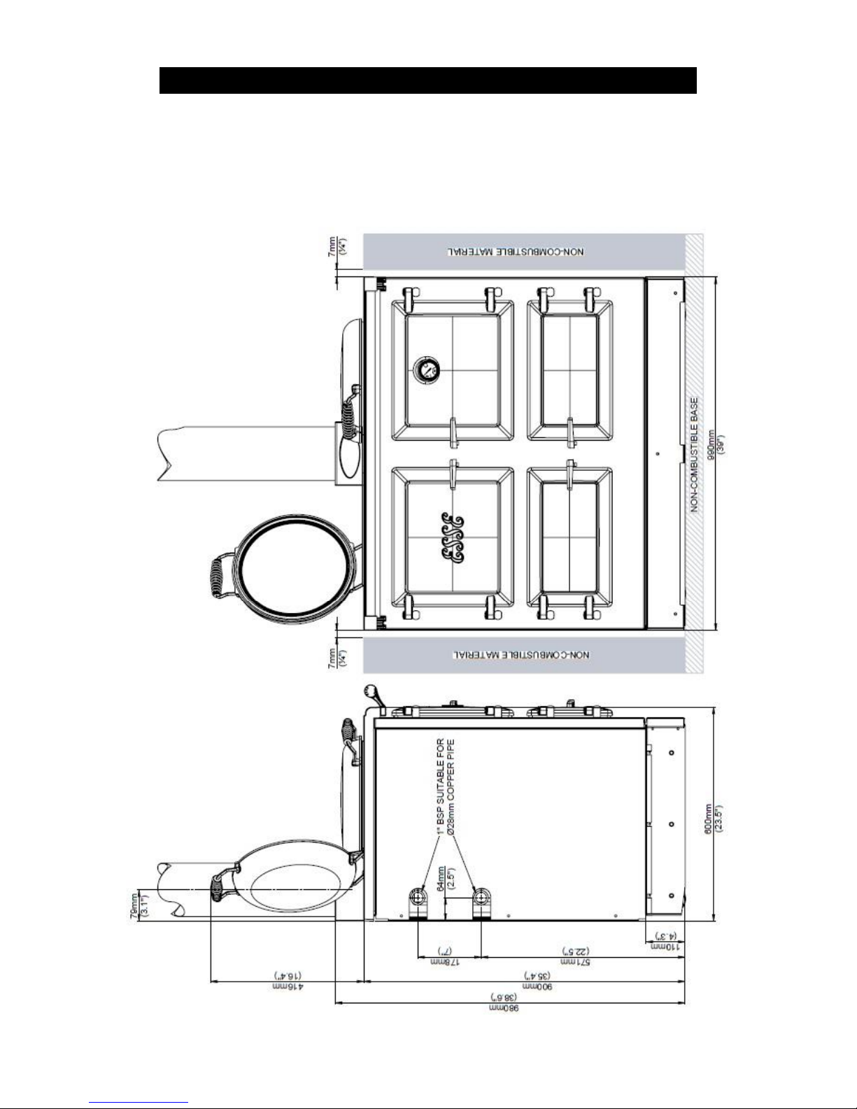
Clearances from combustible materials are 20mm from the sides
and 40mm from the rear.
Page 4
Page 4
990-WNWD-I03-020317
It is also recommended that a smoke alarm and appropriate fire
safety equipment such as a fire extinguisher and fire blanket are
installed in the kitchen as a safety precaution.
An adequate air supply for combustion and ventilation is required.
A purpose provided air vent is necessary. Air openings provided for
this purpose must not be restricted.
Due to our policy of continuous innovation, we reserve the right to
adjust or modify our product without prior notification.
This appliance is not suitable for
installation in a shared flue system
TECHNICAL INFORMATION
Nominal heat output
5.0kW
Combustion air requirements
29m³/h
Weight of the appliance
450kg
Minimum chimney draught
12Pa
Maximum Chimney Draught
25Pa
Mean flue gas temperature
170°C
Flue gas mass flow
10g/s
The cooker data plate is located on the inner door panel of the
bottom right hand oven.
Page 5

Page 5
990-WNWD-I03-020317
CHIMNEY & FLUE INFORMATION
The successful operation of the cooking appliance relies on the
adequate performance of the chimney to which it is connected. The
following chimney guidelines must be followed:
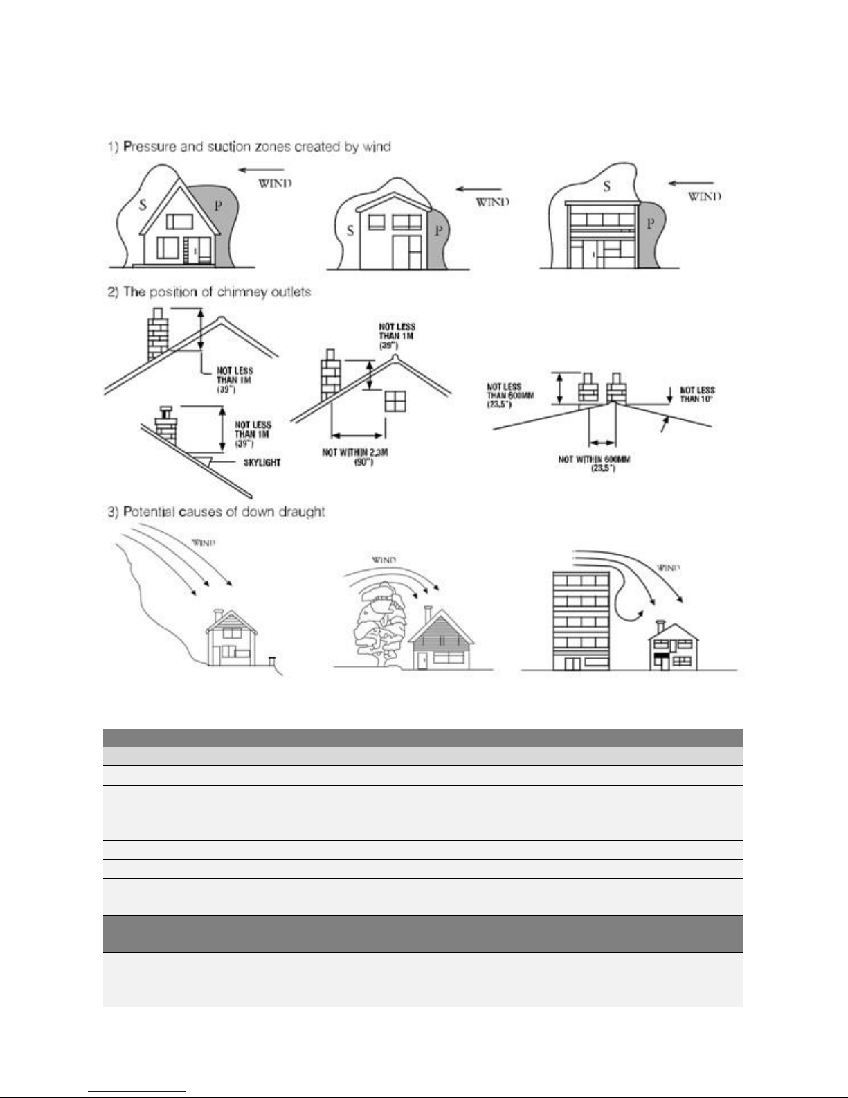
• It should have an internal cross section of no less than 320cm2
(200mm dia.) (If a flue liner is used, it should be 150mm (6’’)
diameter and be made of suitable material for burning wood).
The flue diameter is 150mm (6’’).
• Voids in the chimney should be avoided, as these will prevent a
steady flue draught. The appliance flue pipe should pass
beyond the narrowing of the chimney.
• Be terminated at lease 1m above roof level so that the chimney
does not terminate in a pressure zone.
• If the appliance is installed as a freestanding appliance, it
should not support any part of the chimney.
• Be free from cracks, severe bends, voids, and obstructions.
Be connected to this one appliance only.
New chimneys must be in accordance with local regulations.
The chimney must be capped to prevent ingress of rain.
A flue/chimney access point may also be required so that the
state of the chimney can be checked and any fallen soot
removed.
External flues must be insulated to prevent heat loss.
Do not fit an extractor fan in the same room as the appliance.
Be a minimum 4.6m high from top of the flue box to the chimney
pot.
Page 6
Page 6
990-WNWD-I03-020317
The chimney/flue to which this appliance is being
connected must be swept and examined for
soundness prior to installation. Remedial action
should be taken if required, seeking expert advice
if necessary. Where the chimney is believed to
have served an open fire installation it is possible
that a higher flue gas temperature from a closed
appliance may loosen deposits that were firmly
adhered, with the consequent risk of flue
blockage. It is therefore recommended that the
chimney be swept a second time within a month
of regular use after
The chimney can be checked, before the appliance is installed,
with a smoke match. If the chimney doesn’t pull the smoke it
may suggest the chimney needs attention.
This test is only a guide as an apparently poor flue
may improve once the appliance is installed, lit and
the flue is warmed. If, once the appliance is installed
there is any doubt that the chimney is providing an
adequate draught, a flue draught reading should be
taken.
Page 7
Page 7
990-WNWD-I03-020317
Fig 1: Chimney & flue performance
LOW FLUE DRAUGHT SYMPTOMS: DIFFICULT TO LIGHT AND SMOKE COMING INTO THE ROOM
CAUSE
REMEDY
Cold chimney
Line the chimney
Chimney too short
Extend the chimney
Down draught
Relocate/extend chimney terminal. Fit an anti-down draught
cowl.
Chimney diameter too large
Line the chimney
Chimney obstruction
Clear/sweep the chimney
Restricted air supply
Check for competing draughts (other chimneys, extractor
hood/fans). Fit an air vent if the room is sealed.
HIGH FLUE DRAUGHT SYMPTOMS: FIRE DIFFICULT TO CONTROL, FUEL WILL NOT LAST, COOKER
TOO HOT, APPLIANCE DAMAGE, AND CHIMNEY FIRE.
External wind conditions
combined with chimney
terminal.
Fit stabiliser cowl. Fit flue draught stabiliser.
Page 8
Page 8
990-WNWD-I03-020317
SPACING AND DIMENSIONS.
Fig. 2 990EL Cooker Dimensions
Page 9

Page 9
990-WNWD-I03-020317
UNPACKAGING YOUR NEW COOKER.
Unpack your new Esse Cooker, removing all of the outer packing
and accessories from the top and bottom ovens, including
protective film on the door liners. At this time please examine the
cooker for any damage to the enamel finish and hob glass.
Any damage to the cooker or anything missing, please contact your
supplier for advice.
We ask that you dispose of any packaging in a safe, responsible
manner and recycle where possible.
Page 10
Page 10
990-WNWD-I03-020317
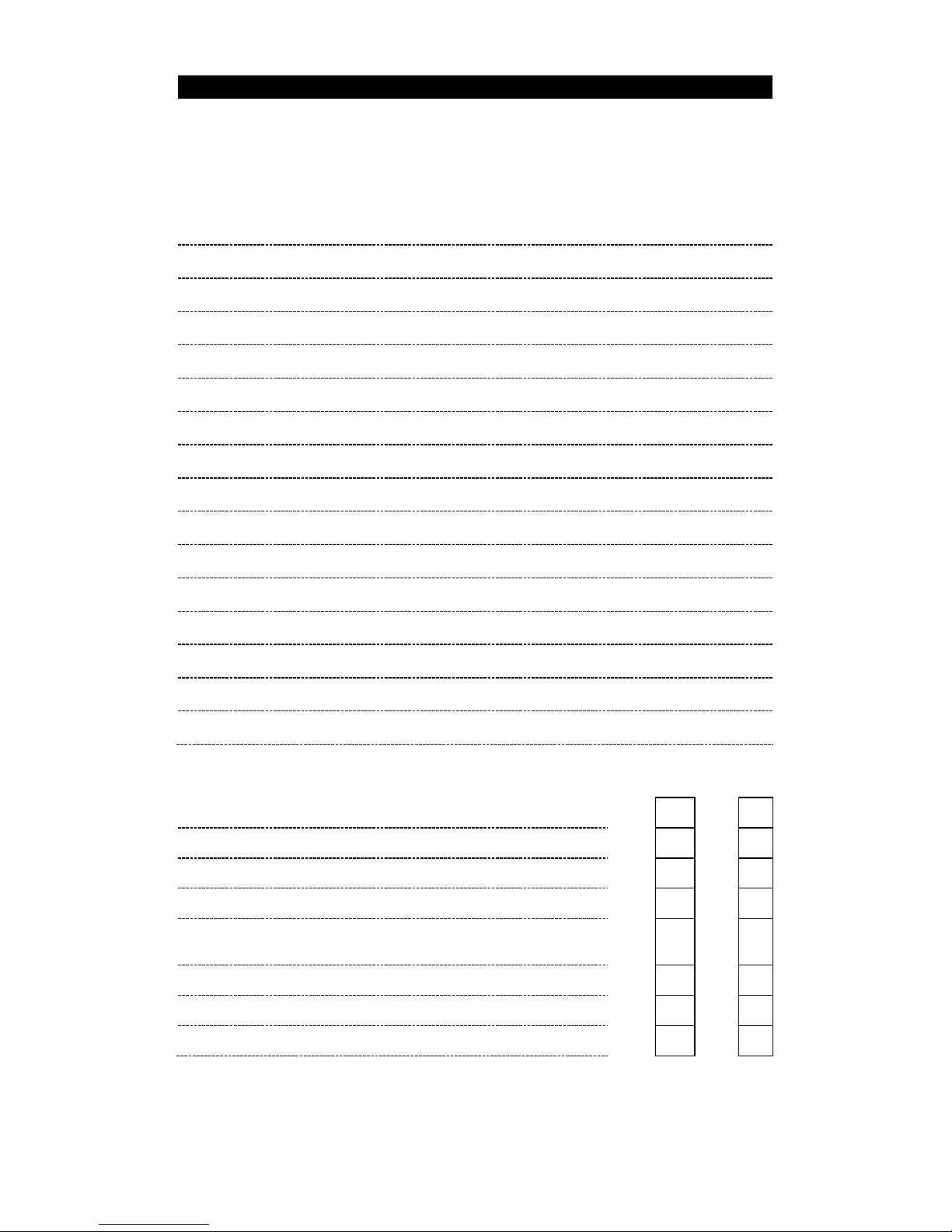
COMMISSIONING CHECKLIST
To assist with any potential guarantee claim please complete the following
information:-
To be completed by the installer.
Dealer the appliance was purchased from:
Name:
Address:
Telephone No:
ESSENTIAL information:
Date Installed
Model Description:
Serial No:
Installation Engineer:
Company Name:
Address:
Telephone No:
Commissioning Checks – to be completed and signed:
Is the flue system correct for this appliance?
Yes No Flue swept and checked for soundness?
Yes No Smoke test completed on installed appliance?
Yes No Spillage test complete?
Yes No
Has the use of the appliance, operation and controls
been explained?
Yes No
Clearance to combustible materials checked?
Yes No
Instruction book handed to the customer?
Yes No
CO Alarm fitted?
Yes No
Signature:………………………………………………..
Print Name:…………………………………………………
Page 11

Page 11
990-WNWD-I03-020317
INSTALLATION
You must be aware of the following safety requirements &
regulations:
This appliance shall be installed in accordance with the regulations
in force.
Read the instructions before installing or using this appliance.
The cooker must be installed in accordance with: All relevant
British Standards / Codes of Practice and the relevant Building / IEE
regulations
Location of the Oven
This appliance is designed for domestic cooking only. Use for any
other purpose could invalidate any warranty or liability claim.
The cooker weighs approximately 450kg and so the floor must be
capable of withstanding the load.
Make sure the cooker is level, use packing pieces if necessary.
Before using your cooker remove plastic protective
covers from inner door panels; lift up lids and hinge
covers.
Flue Connection
The flue pipe used to connect the appliance to the chimney is 6’’
(150mm) in diameter.
A 5”- 6’’ adaptor is supplied to connect to the flue box of the
cooker. (The flue connection is on the top of the appliance, in the
centre at the back.)
Page 12

Page 12
990-WNWD-I03-020317
Important Installation Notes
1. The installation must allow access for adequate chimney
sweeping and flue cleaning.
2. Avoid using bends greater than 45º to the vertical. All flue pipe
sections should be as close to the vertical as possible.
3. All joints in the flue system must be effectively sealed.
4. All flue sockets must face upwards. On completing the
installation of the appliance, the chimney, hearth and walls
adjacent to the cooker must conform to local or national
regulations currently in force. In the United Kingdom, the
appropriate sections of the Building Regulations must be
conformed to.
5. Air inlet grilles should be positioned so that they are not liable to
blockage.
6. An air extraction device shall not be used in the same
room as the appliance unless adequate additional
ventilation is provided.
7. A flue cleaning door should be fitted to provide access for
cleaning the flue and chimney.
8. Check the appliance for soundness of seals between casting
and main components and that all supplied parts and fittings
are correctly fitted.
9. Ensure the appliance is left operational and hand over the
operating instructions and operating tools supplied.
10. Before leaving the installation demonstrate the operation of
the appliance to the user. Explain all controls and flue way
access for cleaning.
Page 13

Page 13
990-WNWD-I03-020317
Placing the cooker
The 990 can be lifted from the pallet it is delivered on utilising ESSE
lifting wheels issued to ESSE retailers. These allow the cooker to be
wheeled into position in the home. Once decoupled from these
wheels and on a flat floor, the cooker can be gently moved
backwards by removing the kick strip & fitting one set of wheels to
the front to lift the cooker, so it can then be pushed back towards
the wall using the built in rollers. In the base of the cooker at each
side at the rear; push on the front of the top casing but not the
towel rail. Do not use the towel rail or the bolster lid handles as a
lifting rail as damage will occur.
Positioning
The appliance should be sited on non-combustible material.
FLUE DRAUGHT TEST
Measure and record flue draught.
Check Ventilation,
Check no extractor fan, other appliance or other flue
interferes.
With D model, check plumbing circuit
Complete commissioning card and return to Esse to
validate warranty.
This test is only a guide as an apparently poor flue
may improve once the appliance is installed, lit and
the flue is warmed. If, once the appliance is installed
there is any doubt that the chimney is providing an
adequate draught, a flue draught reading should be
taken.
Flue Draught Readings
Two flue draught readings should be taken, one with the appliance
at minimum firing rate and one at maximum firing rate. To test the
flue draught, remove the flue box door and fit the flue draught test
plate supplied with the cooker. A flue draft gauge can now be fitted
and the test performed.
Page 14
Page 14
990-WNWD-I03-020317
Minimum reading: The appliance should be lit and allowed to warm
the flue thoroughly. Close the air slider control and ensure firebox
door is fully closed. Allow the burning rate to become steady. The
flue draught reading should now be taken; the minimum required is
12 Pascal’s [Pa] (0.05’’ wg.).
Maximum reading: The air slider controls can now be opened to
allow the appliance to burn at maximum rate. Keep the flue box
door closed. Take a flue draught reading.
Ideally, the flue draught readings should range between 12Pa,
0.12mm (0.05’’ wg.) and 24Pa, 2.5mm (0.1’’ wg.). Any readings
significantly outside this range may indicate the need for remedial
action. Low flue draught symptoms: difficult to light and smoke
coming into the room. With a high flue draught, fuel burns away
very quickly.
Flue Stabiliser
A flue stabiliser can be fitted to reduce the draught through the
appliance if the draught is too high. The flue stabiliser should be
fitted in the same room as the appliance and be the same size as
the flue pipe. (Note: extra ventilation will be required as stated in
the Building Regulations.
SOLID FUEL BURNING
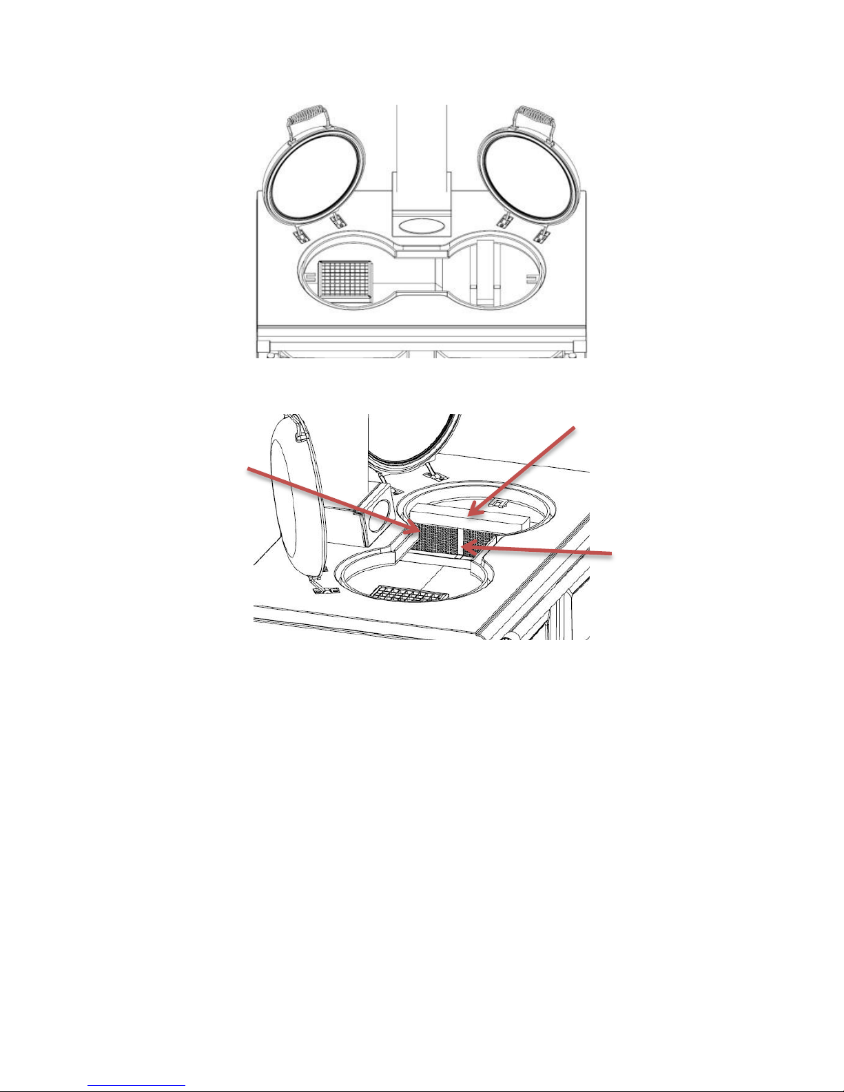
Before attempting to burn solid fuel using the solid fuel
grate and ashpan assembly (these must be ordered
separately) the catalysers and their holding bracket
must be removed. Your cooker is fitted with two
catalytic converters under the hotplate on the right
hand side. The function of these catalysers is to improve
the quality of the smoke emissions.
Fitting the solid fuel burning kit will reduce the output
to water.
Page 15
Page 15
990-WNWD-I03-020317
Fig. 3 Cooker with hotplate removed, front view.
Fig. 4 Cooker with hotplate removed, side view.
GASKET
CATALYSER BRACKET
CATALYSERS
Page 16
Page 16
990-WNWD-I03-020317
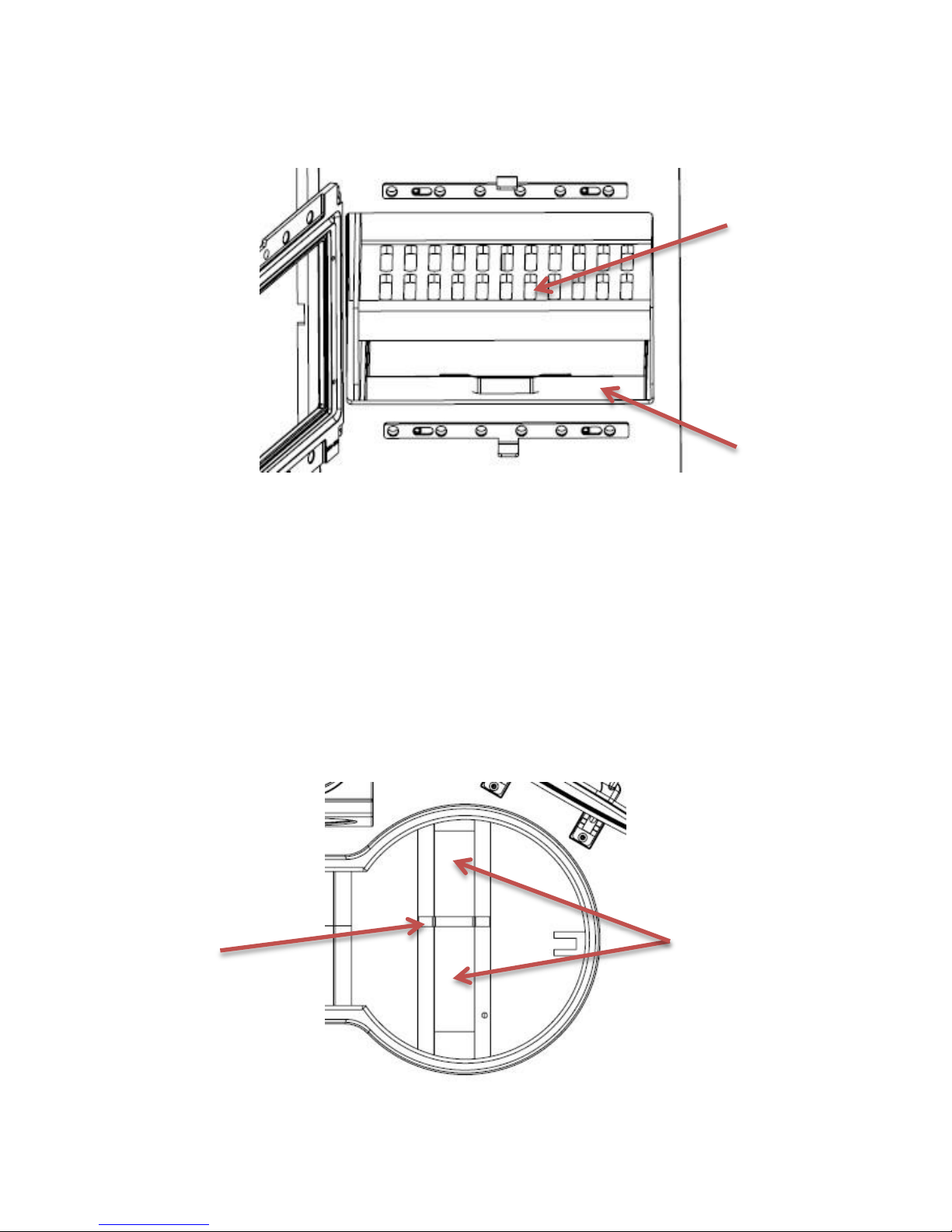
Solid Fuel Assembly
Fig. 5 Solid fuel burning kit
Remove vermiculite base bricks.
Fit solid fuel grate assembly, ashpan support
plate and ashpan.
Remove the catalysers and their holding
bracket from underneath the hotplate.
Fig. 6 Catalysers & Bracket
Ashpan
Solid Fuel
Grate
Catalyser
Bracket
Catalysers
Page 17
Page 17
990-WNWD-I03-020317
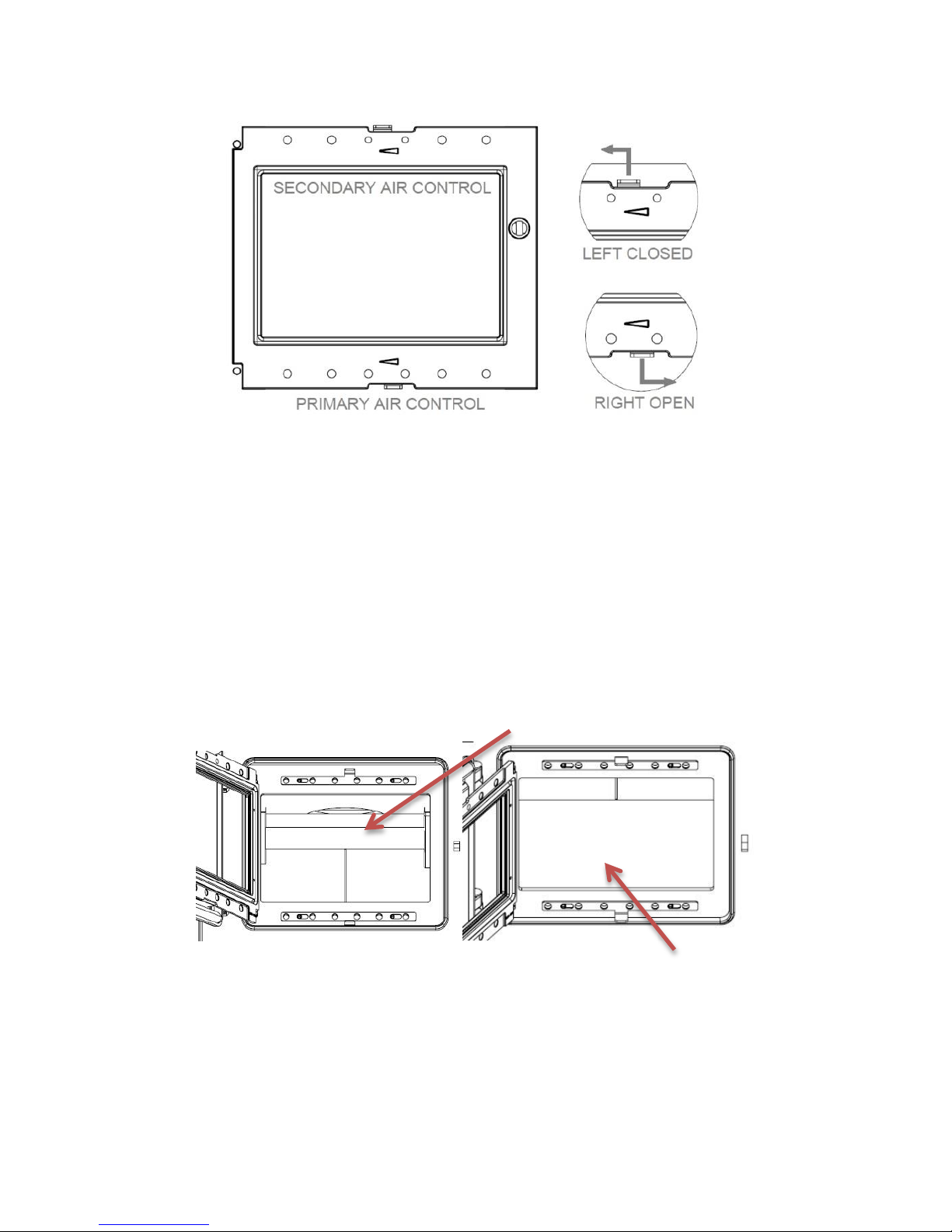
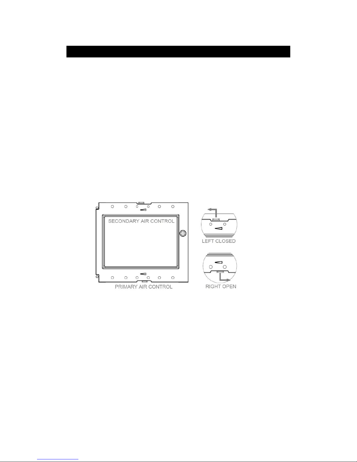
Fig. 7 Air Controls
Fire door closed, with primary and secondary air sliders in the open
position to the right hand side.
Use the Primary Air Slider (lower control) to set the burning rate for
Solid Fuel.
Use Secondary Air Slider (upper control) to set the burning rate for
Wood Burning.
Wood Burning
Fig. 8 Wood burning fire box
To set the cooker back into a wood burning configuration, remove
the grate, ashpan, ashpan support plate and reinstate vermiculite
base bricks, catalysers, catalyser bracket and gasket as shown in
Figure 4.
Vermiculite Base
Baffle
Page 18
Page 18
990-WNWD-I03-020317
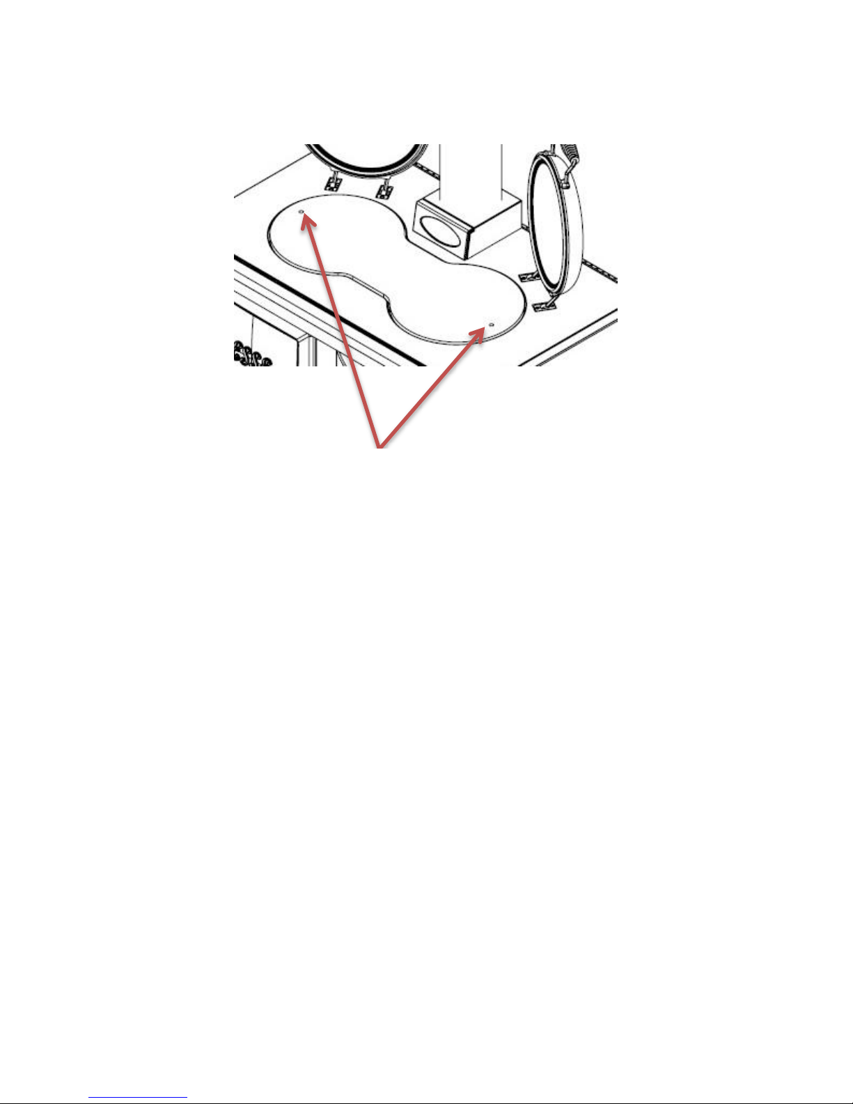
Transit Socket Screw removal
Fig. 9
Upon successful installation, using a 5mm Allen key, remove the
two M6 Transit socket screws (as shown in fig 9 above). Using a
4mm Allen key, insert the two M8x8 grub screws supplied with the
cooker into the holes in the hotplate and adjust until the head of
the grub screw is level with the surface of the hotplate. These grub
screws can be removed and re-fitted during and after cleaning of
your cooker.
Transit socket screws
Page 19

Page 19
990-WNWD-I03-020317
HOT WATER SYSTEM
A. There are two connections, both 1” BSP Female on the left hand
side. General notes follow below.
B. The D boiler is of mild steel construction for use on an open
vented indirect system. A domestic Stainless Steel boiler can be
purchased from your supplier for use on an open vented direct
system if required.
General Notes on Water System: -
1. The cooker will produce hot water at differing rates
depending on how it is operated. Heating control is
manual, no thermostat is fitted.
2. The system must be designed to cope with loads
between the maximum and minimum output. When the
central heating load is turned off there must be
sufficient gravity load to absorb 2.6 Kw for periods when
the oven is being used for cooking, e.g. Domestic hot
water plus gravity operated radiator.
3. An indirect storage cylinder is essential for domestic
hot water supply, irrespective of whether the water
supply is hard or soft. A minimum cylinder capacity of
30 gallons is required. The cylinder should be as
close to cooker as possible.
4. To avoid trapping air in the boiler a 1” BSP connection must
be used on the flow and return tapping, and any reduction in
pipe size thereafter being made on a vertical rising pipe. The
cooker must be level when fitted and the flow pipe must rise
from the boiler. A drain cock must be fitted on the lowest
point of the return pipe and a vent to atmosphere at the
highest point of each circuit. Flow pipe must rise 1 metre
vertical before any change in direction.
5. The cylinder and pipe work should be lagged to avoid heat
loss.
6. The static head must not exceed 60 feet of water.
7. A drain cock should be fitted to the lowest part of the circuit.
8. The total water capacity of the boiler is 3 litres.
9. A heat leak radiator should be fitted to absorb any excess
heat that may be produced.
10.
Page 20
Page 20
990-WNWD-I03-020317
990WN & 990WD Operation instructions
INTRODUCTION
Your Esse 990 is a combination appliance providing a hot plate, 3
ovens of different temperatures, room heat and in the case of the D
model domestic hot water. The firebox behind the top left door has
an inner glass door for viewing the fire, which also houses the air
controls.
The hinged hob covers are referred to as bolster lids and finished in
stainless steel. They are designed to reduce heat losses and
therefore fuel use from the appliance when not cooking, and build
up or conserve higher hotplate temperatures for when cooking is
required.
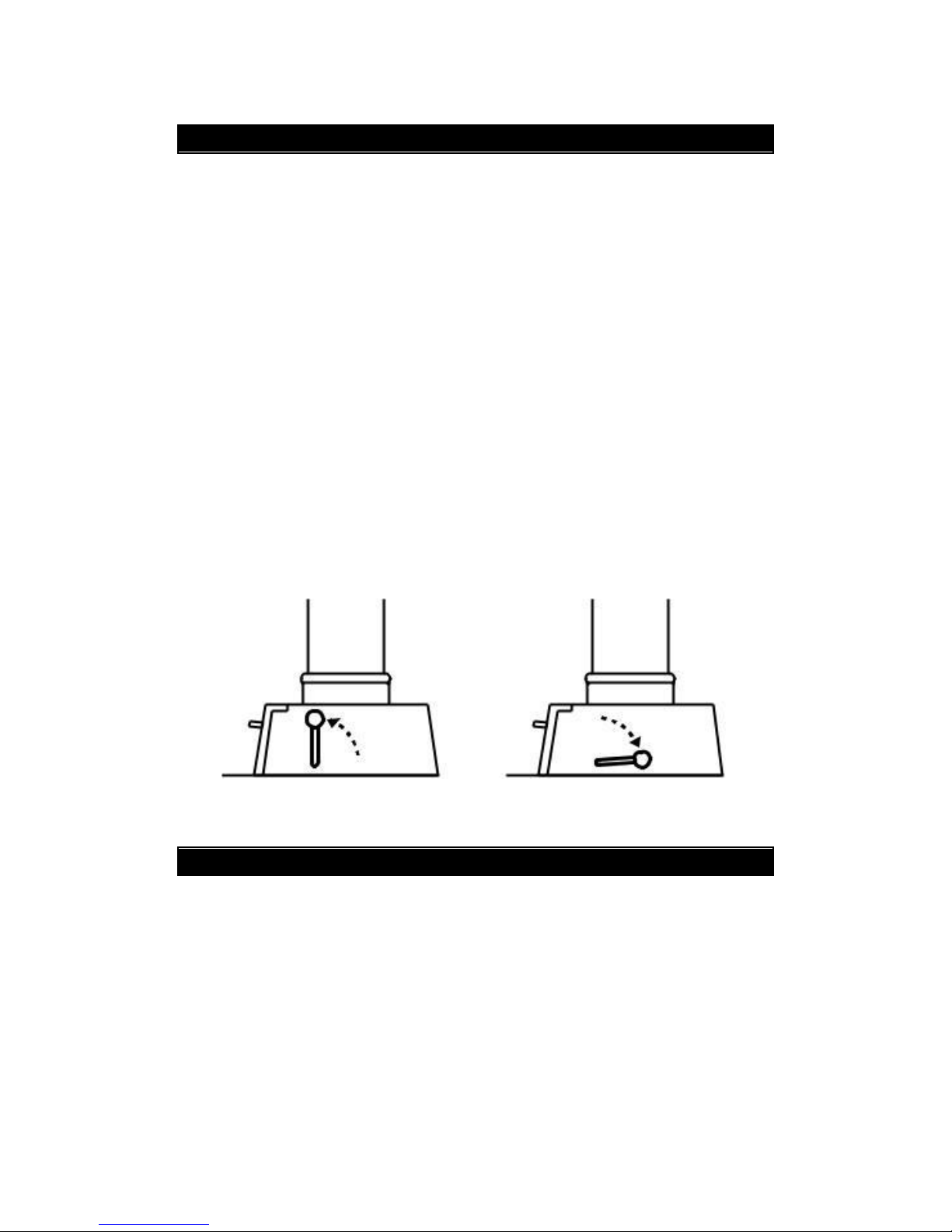
A damper is fitted to the flue connector.
Fig. 10 Damper controls
SAFETY NOTES
Please refer to Installation section of this manual to ensure
appliance has been correctly installed and is connected to a
suitable flue. Failure to do so will seriously inhibit the cooker’s
performance and could be potentially fatal.
Properly installed, operated and maintained, this appliance will not
emit fumes into the dwelling. However occasional fumes from
Flue damper closed
Flue damper open
Page 21

Page 21
990-WNWD-I03-020317
deashing and re-fuelling may occur. Persistent fume emission is
potentially dangerous and must not be tolerated. If the fume
emission persists, please open doors and windows to ventilate the
room. Let the fire burn out or eject and safely dispose of fuel from
the appliance. Once the fire is cold, check the flue and chimney for
blockages and clean if required. Do not attempt to relight the fire
until the cause of the fume emission has been identified and
corrected. Seek expert advice if necessary.
An adequate air supply for combustion and ventilation is essential.
Air openings provided for this purpose must not be restricted. Also
if simultaneous operation of other heating appliances is required
within the kitchen ensure that there is sufficient ventilation. Should
it be likely that children, aged or infirm people approach the
appliance whilst the fire door is open then a fireguard
manufactured in accordance with BS 6539 should be utilised. Also
warn children not to sit or stand on the appliance or use it as a stool
or step to access cupboards or shelves above the appliance.
Avoid the use of aerosol sprays in the vicinity of the cooker when
it is in operation and do not heat any unopened airtight
containers.
Ensure that precautions are taken when deep fat frying, never
leave the appliance unattended and ensure you have fire safety
equipment available such as a fire blanket in case of emergency.
When operating the cooking stove use the tools provided and
follow these instructions carefully.
Always use the glove provided when opening and closing doors, as
handles and surfaces will be hot.
Take care when hanging towels etc. from the rail, particularly in
front of the firebox. The outer door should generally remain closed
for safety.
Do not let children near the oven during use to avoid the danger of
burns or injury. Use of the appliance by the elderly or infirm should
be supervised.
Page 22
Page 22
990-WNWD-I03-020317
The appliance and its accessible parts become hot
during use. Care should be taken to avoid touching
heating elements. Children less than 8 years of age
shall be kept away unless continuously supervised.
Unattended cooking on a hob with fat or oil can be
dangerous and may result in fire, NEVER try to
extinguish a fire with water, instead cover the flame
with a lid or use a fire blanket.
Danger of fire: do not store items on the cooking
surfaces.
BEFORE USING YOUR COOKER
Ensure that any plastic film used to protect surfaces has been
removed from the bolster lids and from the inside of oven door s.
The hotplate has been coated with oil at the factory to prevent
rusting and therefore will require wiping with a damp cloth and
drying with a tea towel or kitchen roll.
Your cooker will be delivered set up to burn wood.
Should you wish to alter this, you will need to remove
the hotplate and lift out the two catalysers and bracket.
Set the cooker in Solid Fuel burning mode see ‘Solid
Fuel Burning’ on page 12.
Page 23
Page 23
990-WNWD-I03-020317
LIGHTING AND CONTROLLING THE COOKER
Open flue damper by moving the lever away from you.
The damper has only 2 positions, open and closed. (Fig.9)
Open the outer cast iron door to reveal the glass door and set
primary and secondary air controls to open position (Fig.10).
Open the glass door and set the fire using rolled up paper,
on top of which small sticks of dry kindling wood has been
placed. Light the fire and depending on how well the
chimney is pulling, close or partially close the glass door until
the kindling is well alight.
Fig 11 Inner fire door & air controls
Reload the fire with small logs or smokeless solid fuel. You may
experience smoke back out of the firebox when reloading as the
chimney may still be in the process of warming up.
Allow the fuel to start to burn and when appropriate continue to
refuel, building up the size of the firebed. When refuelling is
required, open the glass door slowly to minimise the risk of smoke
and flames escaping. Once the fire is well established, close the flue
damper by moving the lever towards you.
Burning wood; set the controls to the desired rate. It is
recommended the primary control is closed once the fire is
established and stable, using the secondary control to regulate
the burning rate. Care must be taken not to close the inner glass
Page 24

Page 24
990-WNWD-I03-020317
door against any logs protruding from the fire or attempt to use
the door to force any logs into the firebox.
Burning smokeless solid fuel, it is recommended the secondary
control is closed, using the primary control to regulate the burning
rate. (Don’t forget to remove the catalyser from under the
hotplate see Fig 4.)
Your cooker should not be used as an incinerator and only
recommended fuels are to be used.
COOKING ON THE HOTPLATE
The hotplate is a heavy iron casting, machined flat on the cooking
surface. Heat up from cold or low can be achieved quite quickly
with a fast burning fire. Leave the bolster lids down to allow the
hotplate to warm up. Once hot, the hotplate will retain
temperature for long periods even as the fire burns down. Please
refer to the table for comparable temperature guides in degrees
Centigrade.
Machined base pans are essential, (ask for our pans leaflet) as heat
passes by conduction. Wipe the hotplate regularly to remove
anything that might interfere with the contact between the
hotplate and the base of the pan.
The hotplate is hottest to the left, over the fire, the
temperature decreasing towards the right. Always keep
the bolster lids down when not using the hotplate.
Food may be cooked directly on the hotplate, for example griddle
scones, burgers, steaks, Welsh rarebit and eggs can be cooked on
the hotplate with the lid closed to cook evenly, and similarly bread
may be toasted under the bolster lid... Bake-o-lite paper is useful to
ensure the hotplate remains clean in such instances.
Page 25
Page 25
990-WNWD-I03-020317
COOKING IN THE OVENS
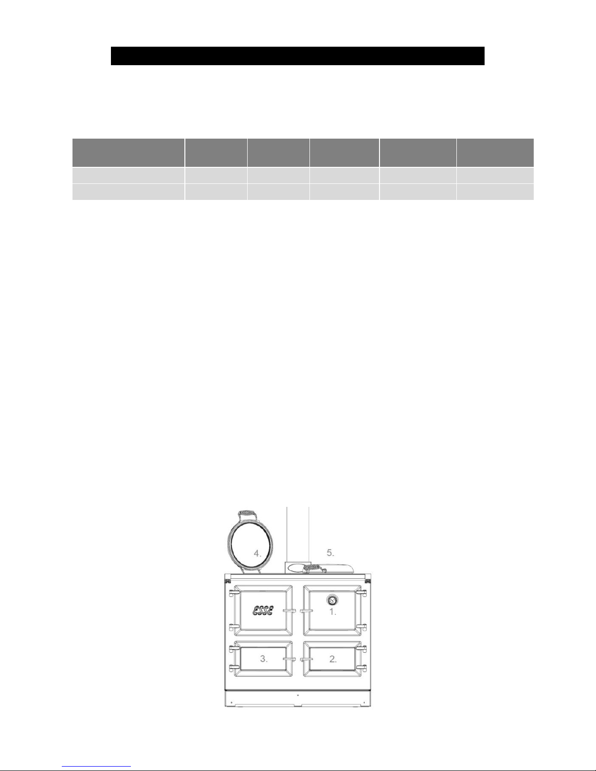
The cooker has 3 ovens. Please refer to the table for comparable
temperature guides in degrees Centigrade.
Fig 12 diagram
1: Main
oven
2: Lower
Oven
3. Firebox
oven
4: Hotplate
(hottest)
5: Hotplate
(coolest)
1 hour from lighting
200°C
120°C
190°C
400°C
140°C
Normal running
200°C
140°C
250°C
320°C
220°C
Temperatures given are approximate and based on refuelling good
quality seasoned wood at approximately 1.4per kg hour. To
increase oven temperatures, refuel the cooker and increase the
burning rate of the fuel by use of the primary and secondary air
controls, and regulate to the desired temperature. Opening the flue
damper will allow heat to pass directly to the chimney via the left
side of the hotplate, useful for boosting the hotplate temperature
without increasing the main oven temperature if required. The
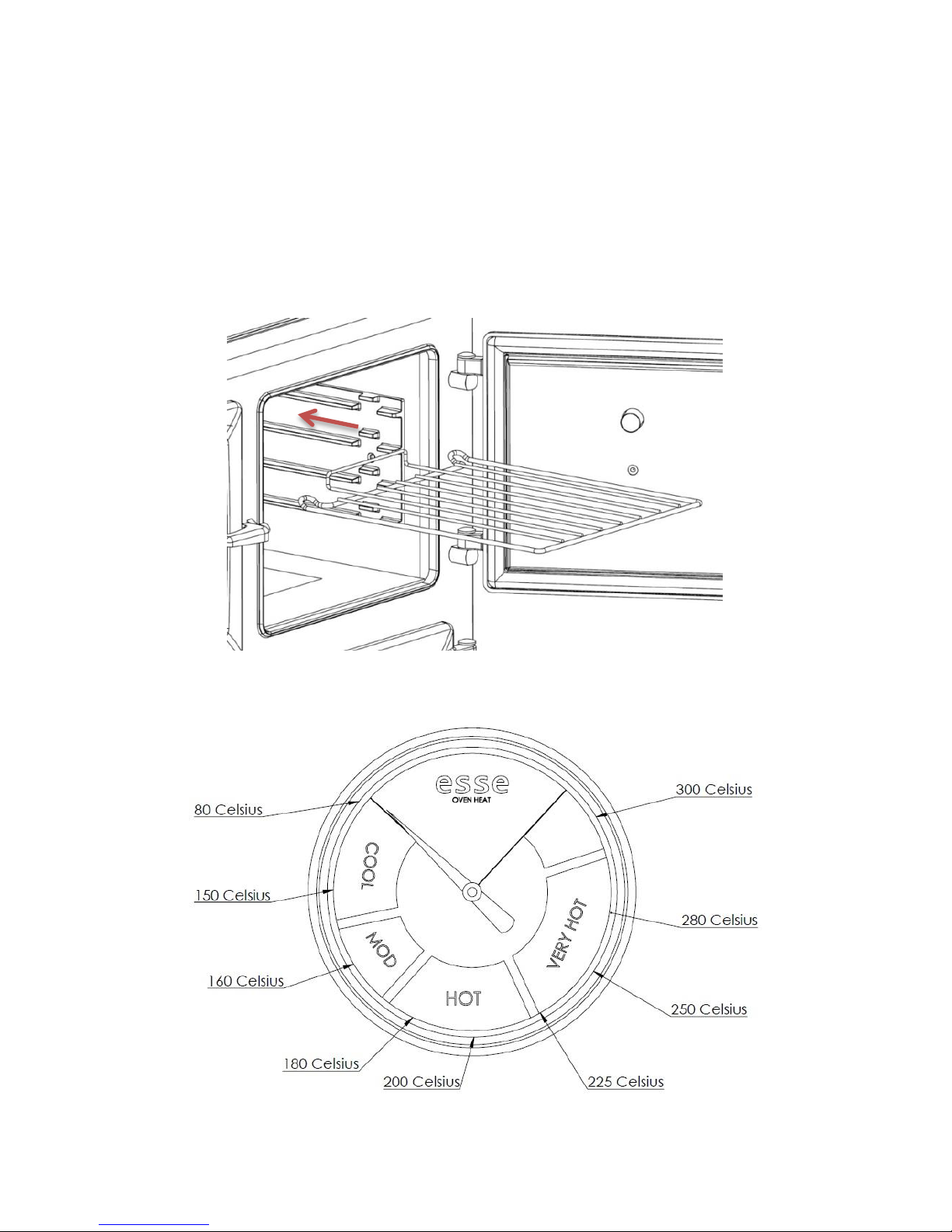
temperature dial on the main oven door provides an indication of
the oven temperature (See Fig.14) and by comparison the
temperature of the adjacent ovens. Since the dial is in the door, the
thermometer will register a lower temperature when the door is
opened although the oven itself will not lose temperature as
quickly. The dial can take a short time to register the correct
temperature once the door is again closed.
Fig 12 Cooker layout
Page 26
Page 26
990-WNWD-I03-020317
The ovens are all of equal depth and each is equipped with wire
shelves which can be set to the desired height. The shelves have
anti-pull out stops on their ends to prevent them from being pulled
out inadvertently; to remove a shelf, pull forward until the stop is
reached, then lift at the front and pull out of the oven. Use reverse
procedure to refit. If the shelves pull straight out then they are in
back to front!
Fig 13
Fig 14 Thermodial
Page 27
Page 27
990-WNWD-I03-020317
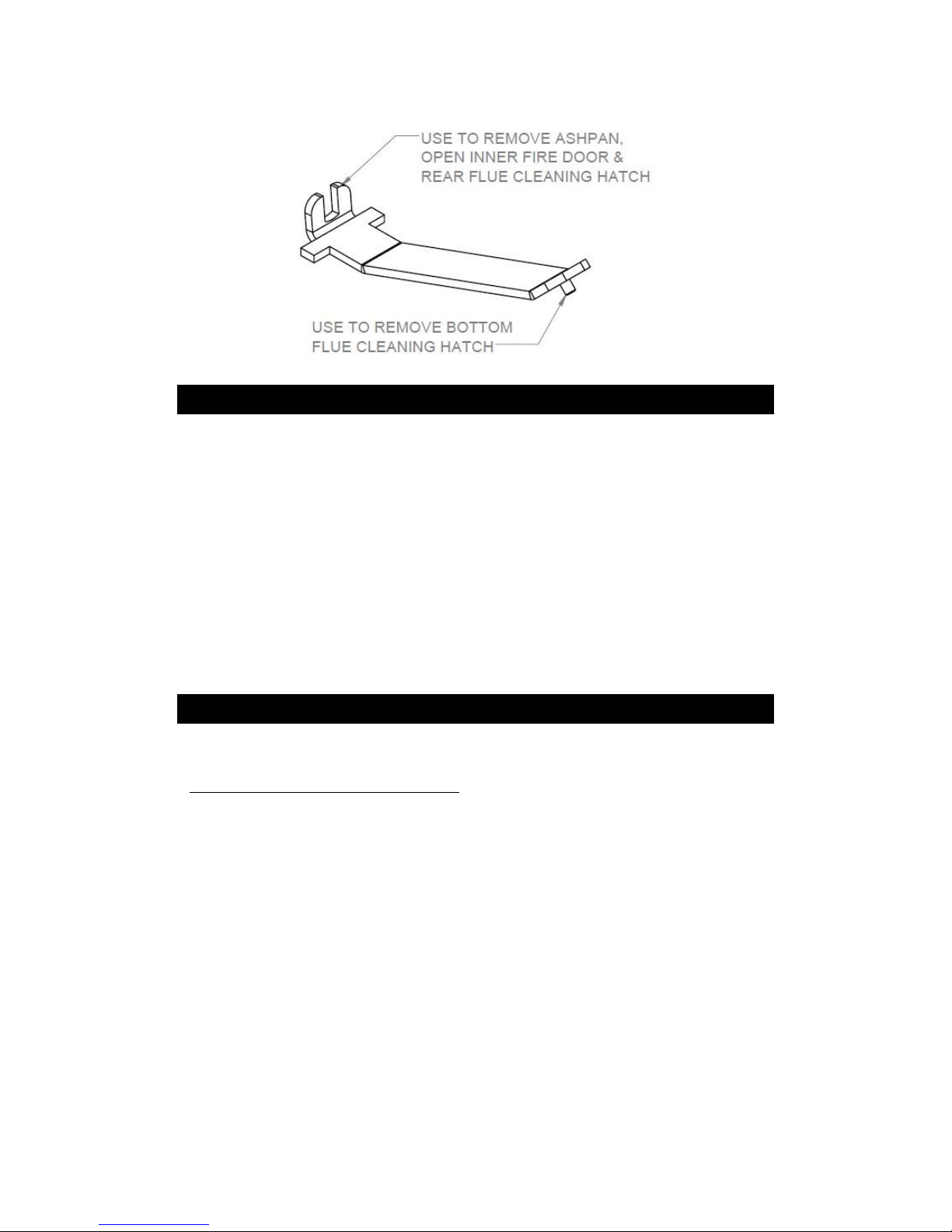
Fig 15 Cooker tool
ASH REMOVAL
When burning wood, only remove small amounts of ash from
the grate, leaving ideally 30mm depth of ash in the bottom for
best performance.
When burning solid fuel, deash regularly.
TYPES OF FUEL
Seasoning and storing firewood.
Wood, which has recently been cut and is still full of sap and
moisture is known as "green" wood.
Greenwood will generally burn poorly and inefficiently, because it
can have over 50% water in its cells. It may be hard to light,
smoulder, not put out any heat and cause more than the usual
amount of creosote to build up in your chimney.
So your aim should be to dry the wood out to below 25% moisture
content, this process is called seasoning. As the name implies, you
should store your wood for a season or so, while it dries, but there
are things you can do to speed up seasoning by cutting the wood
earlier, rather than just before you use it.
Page 28

Page 28
990-WNWD-I03-020317
Wood is composed of bundles of microscopic tubes that were used
to transport water from the roots of the tree to the leaves. These
tubes will stay full of water for years even after a tree is dead. This
is why it is so important to have your firewood cut to length for 6
months or more before you burn it, it gives this water a chance to
evaporate since the tube ends are finally open and the water only
has to migrate a foot or two to escape. Splitting the wood helps too
by exposing more surface area to the sun and wind, but cutting the
wood to shorter lengths is of primary importance.
Here’s how you can tell whether your wood is ready or not. Wellseasoned firewood generally has darkened ends with cracks or
splits visible, it is relatively lightweight, and makes a clear "clunk"
when two pieces are beat together. Green wood on the other
hand is very heavy, the ends look fresher, and it tends to make a
dull "thud" when struck.
Another thing you can do to help is store your wood properly. Store
if off the ground by building the pile on some longer logs (or
whatever method you can devise). A shed or shelter with an open
side makes an ideal storage place, as the air can circulate around
the logs and help to dry them out. Unventilated spaces or plastic
tarps, which never get taken off will prevent the drying and
evaporation process and cause moulds and rot. So, if a tarp is your
only option, take it off frequently to air the wood on fine days. And
remember to put it back on again. Seasoned firewood will reabsorb
large amounts of water if exposed to rain, snow and excessive dew,
which is liable to make it rot and be unfit for making a good fire.
When you build up a store of firewood, remember that the wood
may start to deteriorate after 4 to 5 years, although this is of
course variable and depending on storage conditions and species
involved.
THE WOOD BURNING PROCESS
Understanding what happens when wood is burnt will enable you
to burn wood in a more environmentally friendly way, reduce the
maintenance required for your chimney and get more out of your
wood. There are 3 stages in the wood-burning process:
Page 29

Page 29
990-WNWD-I03-020317
Evaporation
When you light the cooker a lot of energy will be needed at first to
boil away any moisture, which is left in the wood. Using energy to
drive off excess water in firewood robs the cooker of energy
needed for an efficient and clean burn. Also, much of the energy
wasted in evaporating water is energy that could have heated the
hot-plate and ovens. This is a waste of wood, money and effort. The
presence of all that moisture tends to keep "putting out" the fire,
and therefore making it burn very poorly, which tends to produce a
lot of creosote and pollution.
Emissions
As the heat of the fire intensifies, waste-gases (smoke) are released
from the wood.
Unburned smoke is emitted into the air either as pollution, or
condensed in the chimney causing creosote build-up. It takes time
for the air in your chimney to heat up. When it is still cold you get
an effect similar to the condensation of hot breath on a cold
window or mirror. So when the by-products of combustion (smoke
in the form of gases) exit the cooker, and flow up into the
relatively cooler chimney, condensation occurs.
The resulting residue that sticks to the inner walls of the chimney is
called creosote. Creosote is formed by unburned, flammable
particulates present in the smoke. It is black or brown in
appearance. It can be crusty and flaky, tar-like, drippy and sticky or
shiny and hardened. Quite often, all forms will occur in one
chimney system.
If the wood you are using is water logged, or green, the fire will
tend to smoulder and not warm the chimney sufficiently. Wet
wood causes the whole system to be cool, and inefficient. In
contrast: dry wood means a hot fire, which results in a hot flue. A
hot flue means much less creosote clogging up your chimney.
The cooker’s firebox is designed to operate at very high
temperatures to burn the gases and particles released from the
wood, which means less air-pollution.
Page 30
Page 30
990-WNWD-I03-020317
Charcoal
When most of the tar and gasses have burned the remaining
substance is charcoal (ash in its finer form). A hot bed of charcoals
and ash can enhance the combustion process when burning larger
pieces of wood. Start with a small fire to develop a bed of glowing
embers. As the charcoal bed develops and the cooker heats up,
slowly add larger and larger pieces of wood. It takes time to build a
good charcoal bed, but it is well worth the effort. Only empty
excess ash periodically and always leave a bed of ash on which to
light the next fire.
OPERATING TIPS
By taking time to get to know your cooker, following our
maintenance guidelines and using good quality fire-wood you
should enjoy trouble free operation of your wood fired cooker. It is
also worth bearing in mind these useful operating tips:
• Don’t leave the cooker lit for long periods in slumbered down mode
(as you would for overnight burning), open the air control and bank
up the fire periodically to heat up the cooker and flue to prevent
soot build up.
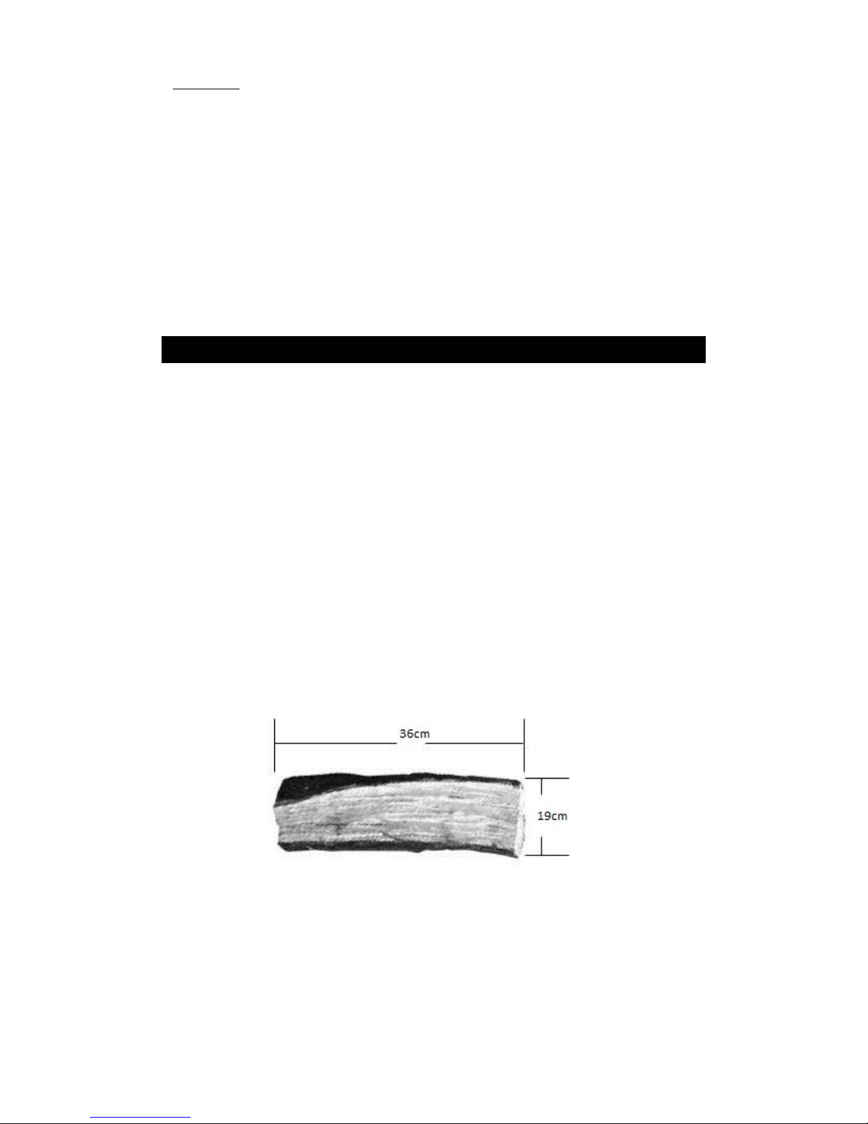
• Cut your logs to the size shown in Fig.16 to minimise the need for
refuelling.
Fig 16
Page 31

Page 31
990-WNWD-I03-020317
WHAT TYPE OF WOOD IS BEST
The difference between 'hard' and 'soft' woods is the density of
their cells or fibres.
As a general rule, the deciduous trees (those that lose their leaves
in the autumn) are usually thought of as hardwoods and the
evergreen trees (such as pines, firs and larches) as the softwoods.
But generalisations are of course always subject to many
exceptions. Some evergreens may well be harder than some
deciduous trees. Birch, for example, is not very hard at all. So we
should understand that there is a whole range of densities
amongst our tree species, including medium dense woods, which
cannot be satisfactorily classed as hard or soft.
Firewood tends to be sold by volume rather than weight. Assuming
that the wood is reasonably dry, the weight of a square foot of
good hardwood may be double of that of a square foot of
softwood. This means that the same volume of hardwood will
provide you with more fuel to burn than an equal amount of
softwood, simply because it contains more substance.
(N.B. The price of hardwood will normally not be double that of
softwood, because it took the same amount of labour to prepare.
So, if a trailer full of hardwood costs more than the same size
trailer full of softwood, the more expensive option may well be the
most economical.)
The other advantage of good hardwoods are that the cooker does
not need to be fed as often and the charcoal-beds made by the
glowing wood may burn more easily overnight.
However, the ideal situation would be to have a store of both
hard and soft woods, because the softer woods also have distinct
advantages. They light more easily than the slower burning
hardwoods and if the softwoods are dry, they create a hotter,
more intense fire. The draught created by the hotter fire moves
the air up the chimney faster.
Page 32

Page 32
990-WNWD-I03-020317
After reading the notes about the burning process, you will
understand that means less pollution in the form of smoke
and less creosote condensation in your chimney.
The denser hardwoods tend to smoulder more easily
when the fire is lit first, so their flue gas temperature will
be much cooler.
Because softwoods like pine and larch contain a lot of resins and
pitch, a popular misconception is that they will fur up the chimney
with creosote more easily than a hardwood like oak. This is not
necessarily true at all. It is not the pitch that is the problem, Rather
it's the water in the pitch. Once the water in the wood has
evaporated, that pitch becomes high octane fuel! When dry,
softwoods burn extremely hot!
There is also the matter of seasoning to be considered. When you
buy wood, it will usually have been cut in the winter of the year you
buy it. Hard woods tend to take longer than softwoods to fully dry
out.
Softwoods cut in the previous winter should, with proper storage,
be ready to burn the next autumn, where-as many hardwoods may
take a bit longer than that. Oak, for example, is very slow to dry out
and ideally left for two years. It is also possible to purchase pre
seasoned wood.
Summarising we can say that it is always sensible to buy this year
for the next years fuel supply and that it is very handy to have both
soft and hardwoods available. You can use the softwoods to start a
good fire and you will have additional control over the fire (in
addition to the cookers controls) by adding slower burning wood
to the faster burning ones if you want to leave the cooker without
tending it for a while. Alternatively you can add some fast burning
softwood logs to the slower hardwood logs to instantly revive a
fire, which has been neglected.
Page 33
Page 33
990-WNWD-I03-020317
THE IMPORTANCE OF A HEALTHY FLUE
The successful operation of your range cooker is entirely dependent
on the adequate performance (pull) of the chimney or flue to which
it is connected. The following maintenance guidelines will be
pointless unless the flue is also maintained and cleaned regularly.
How often it needs cleaning will depend on the quality and
moisture content of the wood you burn but an annual clean is
recommended. A partially blocked or dirty flue can have disastrous
implications for an otherwise perfectly installed cooker as can be
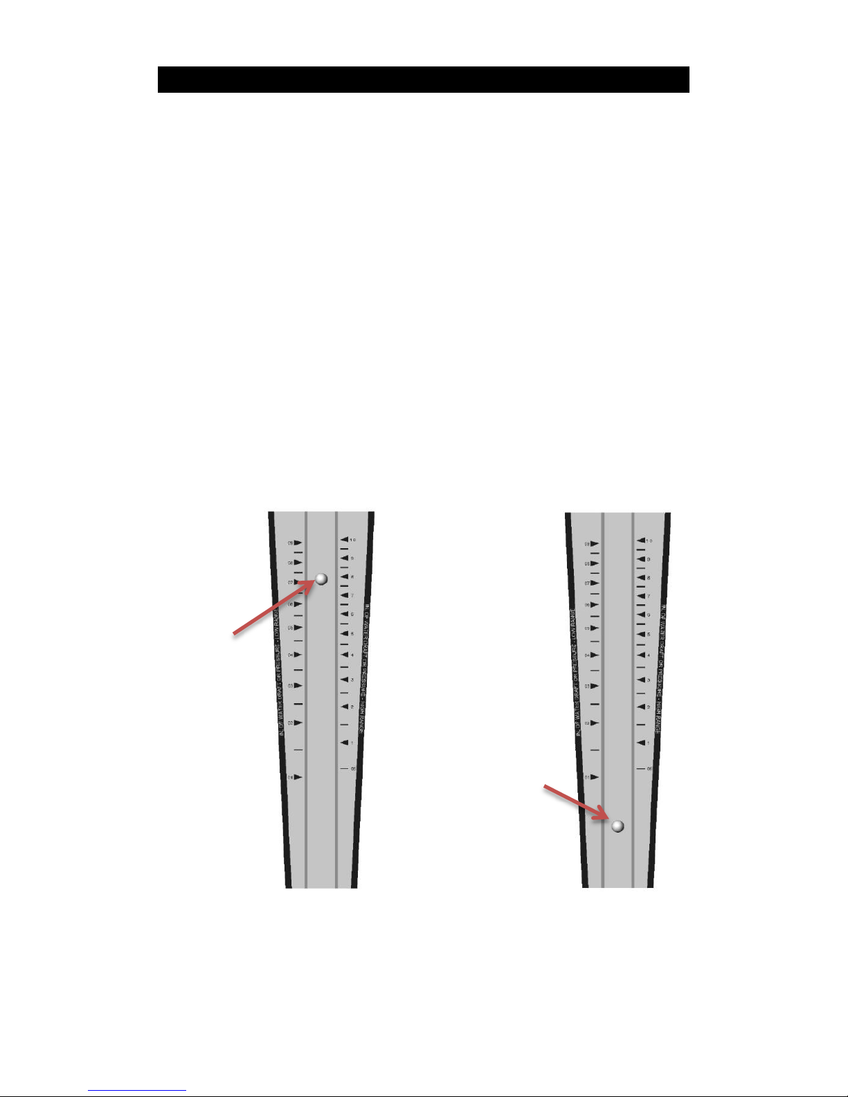
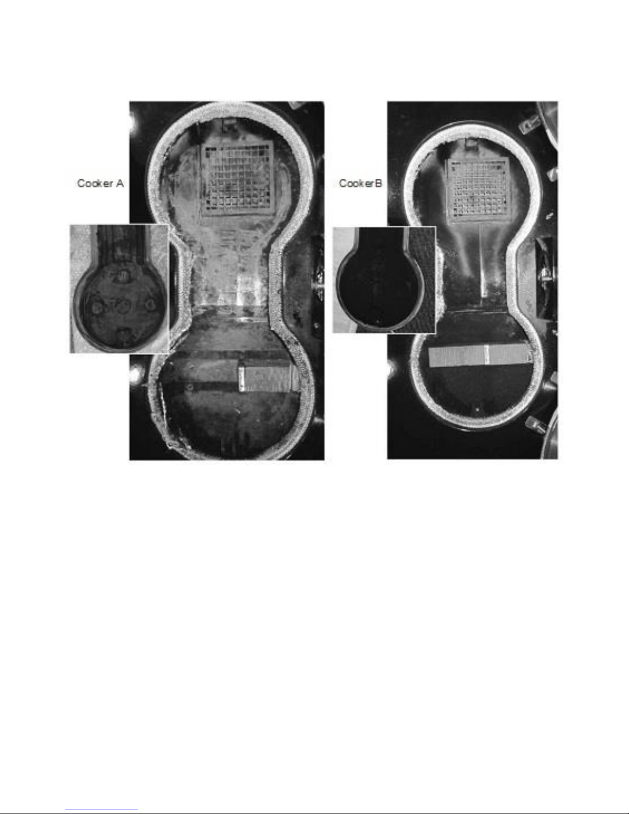
seen in figure17. Cooker A has been used regularly for over a year
following these maintenance guidelines and with a clean flue
drawing correctly. Cooker B was just 6 weeks old when the picture
was taken and shows how quickly tar deposits will build up if the
flue performance is poor and clogged with old soot as it was in this
case.
Fig 17 Healthy flue gauge & Poor flue gauge
Healthy flue: The flue
draught meter shows a
reading (between 12 &
24 Pascal’s or 0.12mm
& 2.5mm or 0.05wg &
0.1wg) which is ideal
for optimum firebox
performance
Unhealthy flue: The
flue draught meter
shows a reading well
below the required
operating range that
will result in poor,
smokey performance.
Page 34
Page 34
990-WNWD-I03-020317
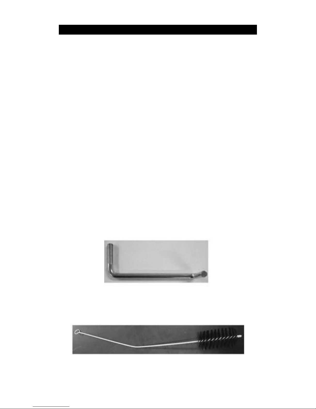
Fig 18 Good draft and poor draft examples
Good draft & clean flue = efficient
wood burning, clear flue ways,
minimal soot and no tar deposits
Poor draft & dirty flue = inefficient wood
burning, blocked flue ways, lots of soot and
tar deposits.
Page 35
Page 35
990-WNWD-I03-020317
CLEANING THE FLUEWAYS – Every 3 months
Always carry out cleaning procedures when the cooker is out and
has been allowed to cool sufficiently to avoid burns. With time and
experience you will be able to gauge the intervals between flueway
cleaning more accurately. It will vary depending on the quality of
your firewood and performance of your flue.
Take time to get to know your cooker and inspect it at regular
intervals for the first 6 months. We recommend that a flue
brush of the type shown below (Fig 18B) is used to clean the
flue ways. Its flexible wire handle is ideal for pushing the
brush head round bends and into narrow spaces.
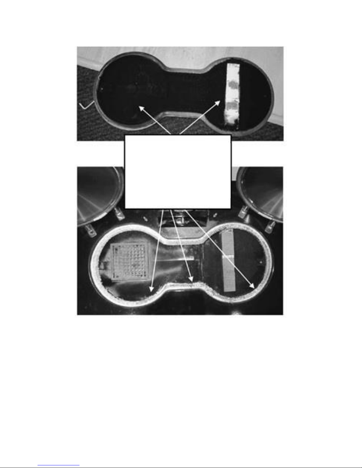
Hotplate & Primary Flueway
Remove the hotplate securing screws and use the hotplate lifting
tools (Fig 18A) that came with your cooker to remove the hotplate
and if required give the surfaces under the hotplate and above the
firebox and top oven a light scrub with a wire brush and vacuum
out any debris.
Fig 19a
Fig 19b
.
Page 36
Page 36
990-WNWD-I03-020317
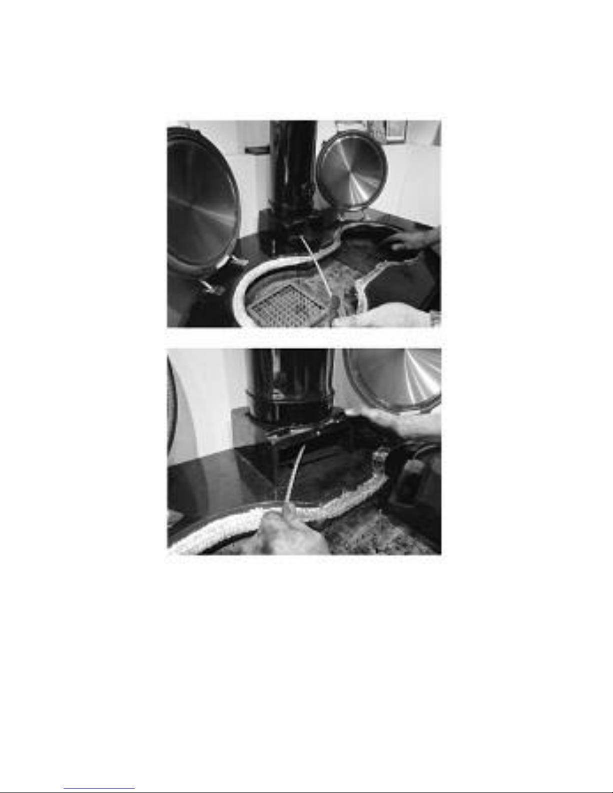
Fig 19c
Lift the hotplate out with care
and place on newspaper or an
old sheet, lightly brush the
surfaces with a wire brush and
vacuum up any debris.
Page 37
Page 37
990-WNWD-I03-020317
Flue box and flueway
Fig 20
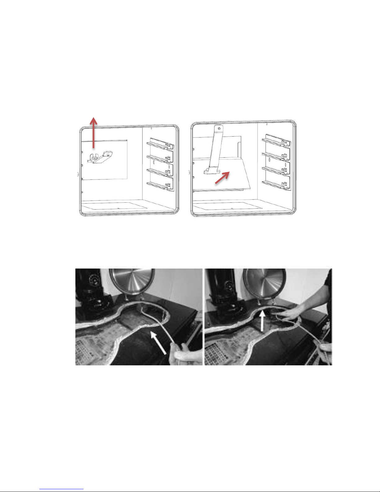
Remove the front of the flue connector box and insert the flue
brush from left to right, angling the brush down at 45°. Once you
find the flue way entrance push the brush down until it stops then
gently but firmly pull back and forth 3 or 4 times then remove the
brush. Dislodged soot will fall into the tray between the ovens.
Additionally there is a removable panel in the rear of top right hand
oven.
Page 38
Page 38
990-WNWD-I03-020317
To use this, open the right hand oven door and remove the oven
shelf. Using the cooker tool, the panel can be lifted vertically by a
few millimetres and then tilted out at the bottom and slid out. This
will now give you access to the rear flueway, which can be brushed
with the flue brush. The soot will fall into the tray between the
ovens.
Fig 21
Right side flueway
Fig 22
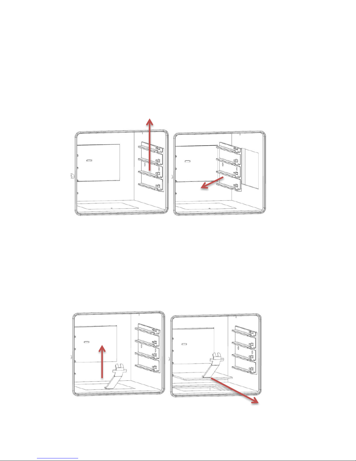
There are two methods to clean the right side flueway. The first
is to insert the brush at a shallow angle as shown above. The
brush will need to turn 90° into the flueway so steady pressure
will be needed to help the brush head round the bend. Once in,
work the brush up and down and front to back as the flue way
runs along the entire depth of the ovens. Again, soot will fall into
the trap between the ovens.
Page 39
Page 39
990-WNWD-I03-020317
The second method is to open the top right oven door and
remove the oven shelf. Then by gripping the right hand shelf
runner, the runner can be lifted a few millimetres and the shelf
runner can be tilted out at the bottom and removed from the
oven. This will give you access to the right side flue way which
you can then use the flue brush to clean the flueway. Again, soot
will fall into the trap between the ovens. If the shelf runner is
reluctant to lift, it can be tapped with a mallet.
Fig 23
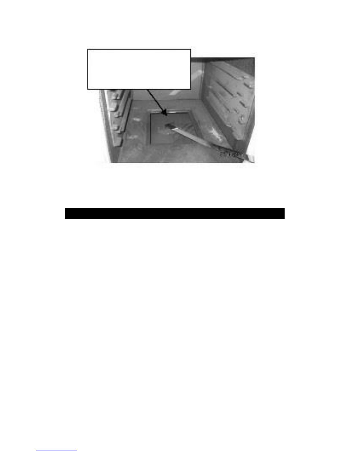
Cleaning the flueway between the ovens
Remove the inspection cover in the base of the main oven and
insert the flue rake, raking from side to side and making sure the
rake reaches the back and the side of the flue boxes. Vacuum the
soot.
Fig 24
Page 40
Page 40
990-WNWD-I03-020317
Fig 25
Due to the access panels for the flueways, the inside of the top right
hand oven may require to be vacuumed after this cleaning.
CLEANING THE EXIT FLUE – Every 12 months
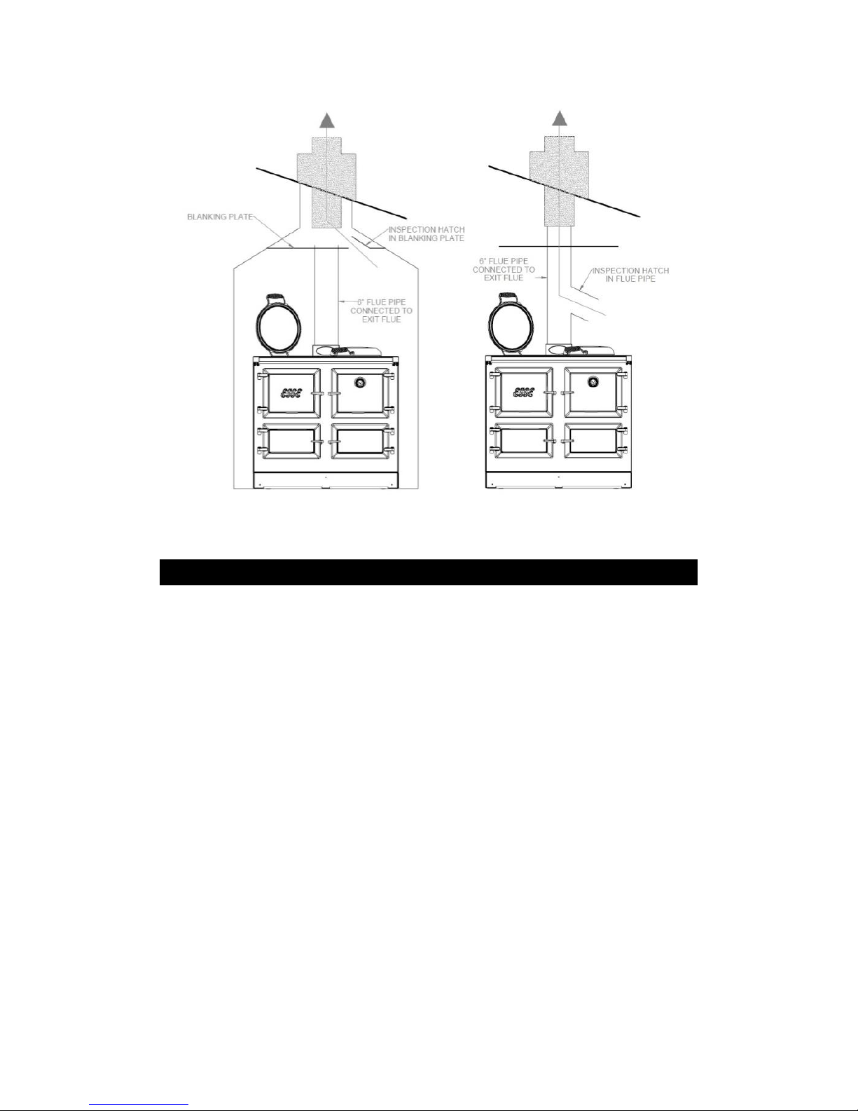
It is essential to maintain the integrity and cleanliness of the flue
to ensure that your cooker continues to perform at its best. When
your cooker was installed the main flue should have been
equipped with an inspection hatch; either in the blanking plate
above the cooker next to the flue pipe (Fig 25) or in the flue pipe
itself.
These hatches are designed to allow periodic access to the flue for
cleaning which should ideally be done by a chimney sweep.
Chimneys and flues vary widely in terms of size, shape, length and
construction, but the principles of the way they work are the same.
Keeping them clean and clear is essential to maintain the optimum
performance of any wood burning or multi-fuel appliance.
With the scrapping tool pull
any soot or granules into the
open space to be vacuumed.
Page 41
Page 41
990-WNWD-I03-020317
Fig 26
CARING FOR YOUR ESSE COOKER.
Your Esse cooker is very easy to keep clean.
The cast iron hotplate helps to clean itself, by carbonising cooking
spills and splashes. Just brush off the carbon dust. For stubborn
stains, don’t be afraid to use a wire brush on the cast iron hotplate
and inside the ovens.
Splashes and spills on the vitreous enamel should be wiped away as
soon as possible, using a damp soft cloth. Micro-fibre cloths are
especially good for this. Never use a cold wet cloth on any
enamelled surfaces as the thermal shock can cause crazing.
If spills have become baked on to the enamel, use soap filled pad,
not too coarse, so as to avoid scratching enamel. DO NOT use oven
cleaners.
Page 42

Page 42
990-WNWD-I03-020317
Likewise the inner door panels and inner bolster lids can be cleaned
with a cream cleanser or for more stubborn marks, a soap filled
pad. The linings will show marks and discolour with use, but with
regular cleaning will maintain its look for longer.
The chromed bolster lids and handrail can be cleaned with a damp
soapy cloth, followed by a wet cloth, finishing by polishing with a
clean dry cloth.
The enamelled surfaces can be cleaned with glass cleaner to help
get a good streak free shine. Any spillage of milk or fruit juices on
to the enamelled surfaces must be wiped up straight away, as the
acidity may stain the front.
Some components such as the side panels are powder coated
(painted) and nothing abrasive should be used on them. Use a soap
filled pad instead.
If the cooker is finished in the ‘Matte Black’ painted finish,
additional care must be taken not to use any chemicals or abrasive
cleaners. Use a light brush or lint free cloth instead.
If the cooker is not going to be used for an extended period of time,
we advise that the cooker be cleaned thoroughly, the ovens and
hotplate can be wiped over with a light coating of cooking oil, the
bolster lids left up and the doors left slightly ajar.
During the life of your cooker it may be necessary to adjust the
door handles and change the door ropes. The door handles can be
adjusted using the adjustment screw on the lift up latch part of the
handle. A video on how to adjust the door handle is on the Esse TV
section of www.esse.com. Replacement door ropes can also be
purchased form www.esse.com
Page 43
Page 43
990-WNWD-I03-020317
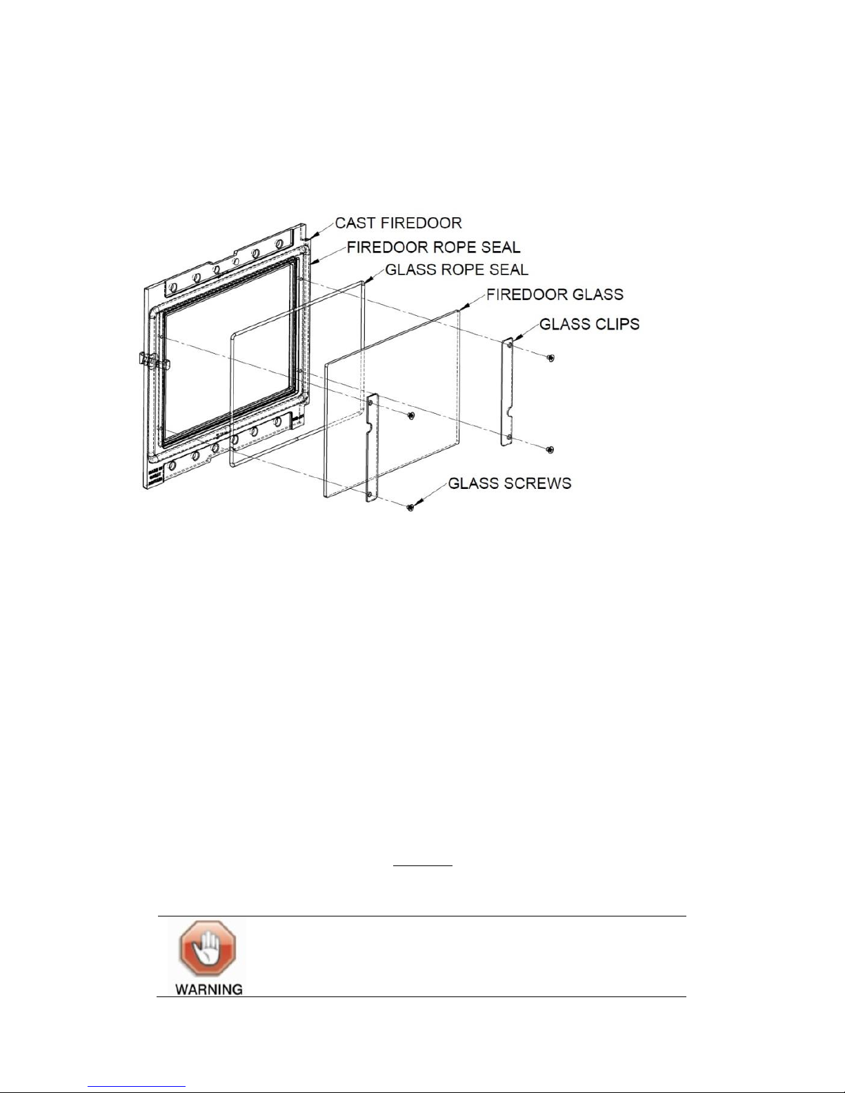
Replacing the firebox door glass:
The firebox door glass can be changed easily if damaged or broken.
Fig 30
1. When the cooker is cool, open the firebox outer door and
the firebox inner door.
2. Remove the 4 glass screws, clips and washers (take care to
support the glass to ensure it doesn’t fall out and break, or
of any sharp edges if the glass has broken.
3. The glass can now be removed. It may require a tap of the
hand to get it off the seal.
4. If replacing the seal, the rope seal can now be removed
and the rope groove cleaned.
5. A replacement rope seal (Part No:
ROPE/CUT.WHT/3x1040mm) can now be fitted in place.
6. A new glass panel (Esse Part Number: 990-007C [Glass
271x190x 4mm thick ceramic glass]) can now be fitted
using the existing washers, glass clips and screws.
WARNING: Do not use normal glass or
other substitute materials in the inner
firebox door.
Page 44
Page 44
990-WNWD-I03-020317
WARNING: Do not clean the inner firebox
door glass when hot.
REPLACEMENT PARTS
Flexible Flue Rake
2040-807 S
Hotplate Screw
CENT-118 S
Hotplate Lifting Tool
2040-400 BO
Flue Brush
WN/WD 3"DIA FLUE BRUSH
Hotplate Rope
ROPE/CUT.WHT-T/25x1800
Bolster Rope
ROPE/CUT.WHT/8x1800-C
Catalysers
990 CAT: 2.5 x 7.5 x 2 (16),
NOTCH, BI (CAT 2-1 PER UNIT)
Vermiculite Bricks
(Base/Front/Side Bricks) :-
Base Brick
990-009B
Front Brick
990-009C
Side Bricks
990-001
Vermiculite Baffle
990-008
Ashpan
990-054
Ashpan Base
990-053
Stainless Steel Combustor
WCKCU-012
Solid Fuel
Grate 990-051
Oven Rope
ROPE/CUT.GRY/18x1360-G
Firebox inner door glass
990-007C
Firebox inner door glass rope
ROPE/CUT.WHT/3x1040mm
Page 45

Page 45
990-WNWD-I03-020317
GUARANTEE.
CONDITIONS OF GUARANTEE
Your ESSE is guaranteed against defects arising from faulty
manufacture for 2 years when supplied by an ESSE Specialist.
Upon registration of the warranty, ESSE will extend the guarantee
period to 5 years from purchase. Your details must be registered
with us by either returning the completed warranty card or by
completing registration on-line at www.esse.com. The warranty
must be registered within 1 month of installation to qualify for the
5 year warranty.
The appliance must be only used for normal domestic purposes and
in accordance with our instructions, be correctly installed and
serviced.
The guarantee does not cover:
Installation
Wear and tear
Parts deemed to be replaceable or service parts including electrical
components that may be replaced during the normal usage of the
appliance.
Enamel damage caused by impact, spillage, water ingress or
condensate attack from flue or by using unsuitable fuels.
This guarantee is personal to the original purchaser and not
transferable.
Any cooker or defective part replaced shall become the Company’s
property
HOW TO PROCEED WITH A COMPLAINT
If you have cause for dissatisfaction with your cooker, you should
first contact your ESSE dealer, who will bring your concerns to our
attention. We will assess the nature of the complaint and either
send replacement parts for your dealer to fit, or arrange for an ESSE
engineer to inspect the appliance and carry out any work that may
be deemed necessary. If the fault is not actually due to faulty
Page 46

Page 46
990-WNWD-I03-020317
manufacture but some other cause i.e. misuse, failure to install
correctly, or failure to service at regular intervals, a charge will be
made to cover the cost of the visit and any new parts required.
INTERMITTENT USE OF YOUR COOKER
In the event of intermittent use and prolonged shutdown, it should
be noted that in some circumstances enamel may be displaced due
to ingress of damp. Whilst this is rare, it is most likely to occur in
situations where the unused cooker remains in an unheated
property. There is a layer (known as the ground coat) between the
vitreous enamel surface and the cast iron. Ground coat is porous
and if exposed (e.g. after a chip in the vitreous enamel coat), may
allow damp to penetrate behind the vitreous enamel and spread
through the ground coat. Surface oxidisation of the cast iron may
thereafter occur, causing the vitreous enamel to fall off. Such
damage will not be covered by your warranty. We recommend that
a light coating of petroleum jelly be applied to any damaged areas
when the cooker is not in use to help keep out the damp, in
addition to following the ‘caring for your Esse cooker’ instructions
on page 43.
CUSTOMER CARE
In the event you should require spare parts, please order through
your ESSE dealer or by contacting Esse via telephone (+44 1282
813235) or our website, www.esse.com.
Page 47

Page 47
990-WNWD-I03-020317
Page 48
Page 48
990-WNWD-I03-020317
ESSE Engineering Limited, Ouzledale Foundry, Long Ing, Barnoldswick,
Lancashire
BB18 6BJ
Tel. 01282 813 235, Fax: 01282 816 876
Website and On-line Store http://www.esse.com
 Loading...