

Page 1
Page 2

CONTENTS.
Statutory Warnings
P.2 Timer
P.12
Technical Data
P.5
Ovens, Grill & Slow Cook
Oven
P.13
Unpacking your New
Cooker
P.5 Induction Zone
P.18
Installation
P.5 Hotplate
P.36
Connecting your
Cooker
P.6
Oven Steam
Vents
p.37
Your Cooker
P.7
Caring for your Esse
Cooker
P.38
Spacing & Dimensions
P.8 Extraction
P.40
Commissioning
Checklist
P.10
Guarantee
P.40
Control Panel
P.11
STATUTORY WARNINGS.
Please read these operating instructions carefully for full
information on the safe installation, use and care of your new Esse
appliance.
This appliance must be correctly installed in accordance with these
instructions by a suitably qualified person.
We cannot accept responsibility for damage to persons or items
due to poor or incorrect installation of this appliance.
Make sure that the voltage (230v) and frequency (50Hz) of the
mains supply correspond to the details on the cooker data plate
which is located on the inside of the control compartment panel
door.
Maintenance and servicing work must only be carried out after the
power supply has been disconnected by switching off at the socket
and removal of both plugs.
Page 3
Page 3
990ELX-I02-220319
Due to our policy of continuous innovation, we reserve the right to
adjust or modify our product without prior notification.
Do not let children near the oven during use to avoid the danger of
burns or injury. Use of the appliance by the elderly or infirm should
be supervised.
An electromagnetic field is generated when the
induction hob is activated. Although unlikely that
this could affect a pacemaker of other medical
device, we recommend that individuals with these
devices consult the device manufacturer or your
doctor if you have concerns.
The appliance and its accessible parts become hot
during use. Care should be taken to avoid touching
heating elements. Children less than 8 years of age
shall be kept away unless continuously supervised.
This appliance can be used by children aged from 8 years and above
and persons with reduced physical, sensory or mental capabilities
or lack of experience and knowledge if they have been given
supervision or instruction concerning use of the appliance in a safe
way and understand the hazards involved. Children shall not play
with the appliance. Cleaning and user maintenance shall not be
carried out by children without supervision.
Unattended cooking on a hob with fat or oil can be
dangerous and may result in fire, NEVER try to
extinguish a fire with water, instead switch off the
appliance, cover the flame with a lid or use a fire
blanket.
Danger of fire: do not store items on the cooking
surfaces.
Page 4

Page 4
990ELX-I02-220319
If the Induction zone glass is cracked or broken the
cooker MUST NOT BE CONNECTED and no part of it
may be used. Switch off and unplug the appliance
to avoid possibility of electric shock.
Metallic objects such as knives, forks, spoons and lids should not be
placed on the hob surface since they can get hot.
Any spillages on the heat conserving lids should be removed from
the lid before opening.
Do not use a steam cleaner to clean any part of this appliance.
This appliance is not intended to be operated by means of an
external timer or separate remote-control.
If any of the supply cords are damaged, it must be replaced by the
manufacturer, its service agent or similarly qualified persons in
order to avoid a hazard.
Induction Zone: After use, switch off the hob element by its control
and do not rely on the pan detector.
During cooking, food naturally produces steam, which is vented
away to prevent excessive build-up within the ovens. As steam can
condense to water droplets on the cooler outer trim of the oven, it
may be necessary during cooking to wipe away any moisture with a
soft cloth. This will also help to prevent soiling and discolouration
of the oven exterior by cooking vapours.
Page 5
Page 5
990ELX-I02-220319
TECHNICAL DATA
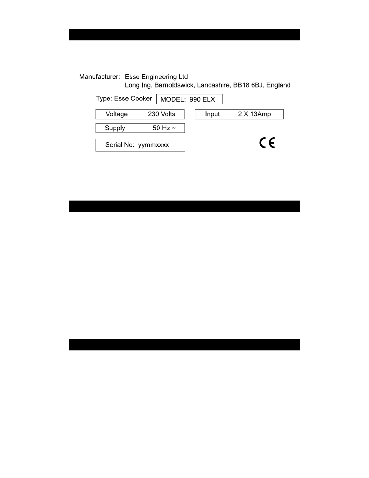
Fig.1 990ELX Cooker data plate
The cooker data plate is located on the inner door panel of the
control compartment.
UNPACKAGING YOUR NEW COOKER.
Unpack your new Esse Cooker, removing all of the outer packing
and accessories from the top and bottom ovens, including
protective film on the door liners. At this time please examine the
cooker for any damage to the enamel finish and hob glass.
Any damage to the cooker or anything missing, please contact your
supplier for advice.
We ask that you dispose of any packaging in a safe, responsible
manner and recycle where possible.
INSTALLATION.
You must be aware of the following safety requirements &
regulations:
This appliance shall be installed in accordance with the regulations
in force.
Read the instructions before installing or using this appliance.
Page 6

Page 6
990ELX-I02-220319
The cooker must be installed in accordance with: All relevant
British Standards / Codes of Practice and the relevant Building / IEE
regulations
Location of the Oven
This appliance is designed for domestic cooking only. Use for any
other purpose could invalidate any warranty or liability claim.
CONNECTING YOUR COOKER
For your own safety we recommend that a competent person
installs your cooker. This cooker is designed to be installed using
two standard 13 Amp plugs or a single hardwired connection to a
40 Amp cooker spur. A qualified electrician is not required if the
cooker is supplied with 13 Amp plugs but is required for hardwired
connections.
Electrical connection
Ovens with a three-pole power supply cable are designed to
operate with alternated current at the supply frequency and
voltage indicated on the data plate (located on the inner door panel
of the control compartment).
Connecting the power supply cable to the mains:
The appliance is supplied fitted with either two 1.5 metre cables
and two normalized 13 amp plugs, or a single 40 Amp cable for
hardwiring, which correspond to the load indicated on the data
plate. Before making the connections check that: the circuit
breakers or fuses of the home system can support the appliance
load (see data plate); the power supply system has a sufficient
earth connection which complies with the provisions of current
regulations and the law; there is easy access to the socket. Do not
use coiled extension cables or adapters as these could cause
overheating, burning or RCD trip out..
Page 7

Page 7
990ELX-I02-220319
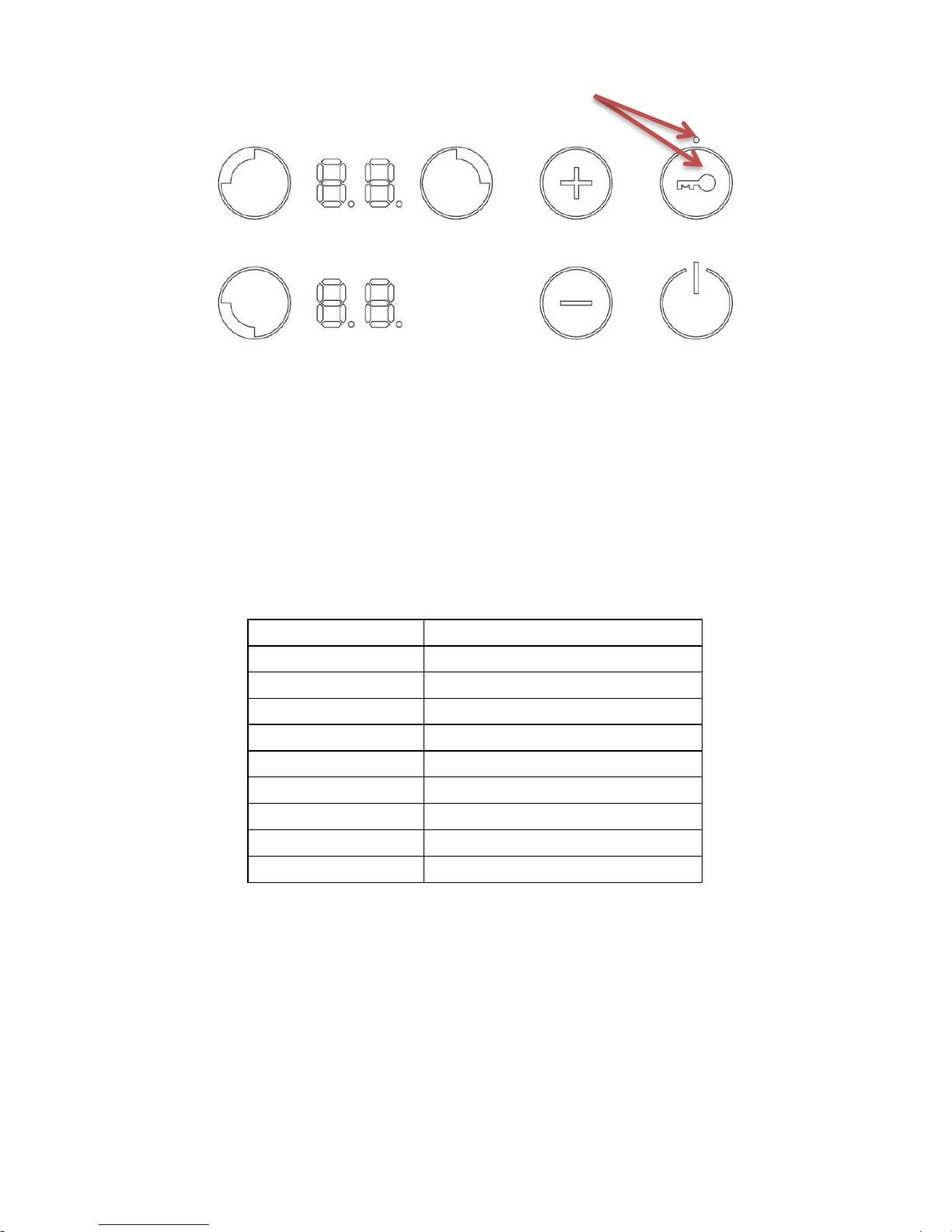
Calibrating the induction unit
Before using your induction hob, you must ‘calibrate’ the sensitivity
of the controls. It is crucial that this is done correctly, to ensure that
the induction hob operates appropriately.
To calibrate the controls on your induction unit please follow the
below steps:
1. Ensure that the power to your ESSE 990 ELX is switched
off at the wall.
2. Turn the power to your ESSE 990 ELX on at the wall.
a. The induction hob will run through a start-up
routine for a few seconds, during which time all
the numerical LEDs will show ‘8’.
b. When the start-up routine is complete, a single
LED above the ‘lock button’ on the control panel
will be lit up.
3. Firmly press the ‘lock button’ for 2 seconds, until the LED
goes out.
Your ESSE 990 ELX induction hob controls are now successfully
calibrated
You must recalibrate the induction hob controls every
time power is lost. I.E. when your ESSE 990 ELX is
switched off at the mains, or there is a power cut.
Page 8
Page 8
990ELX-I02-220319
YOUR COOKER.
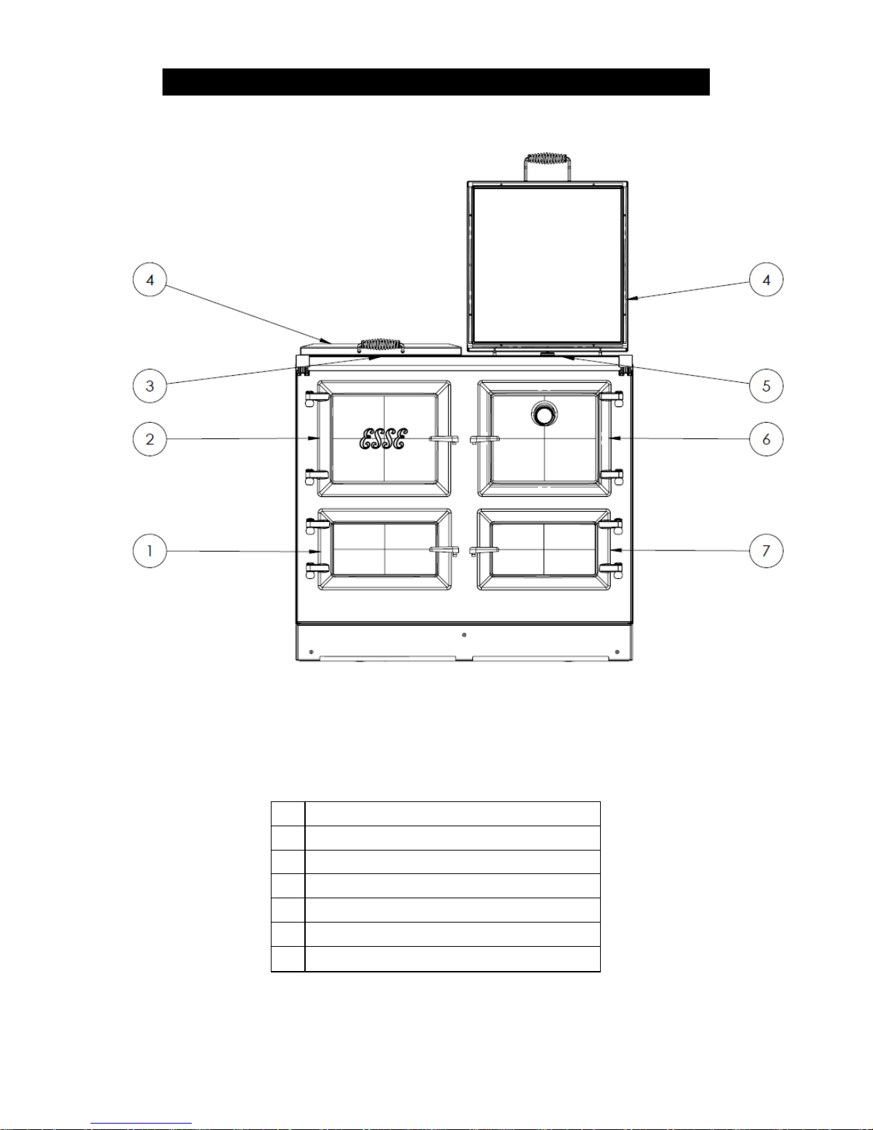
Fig.2 990ELX Cooker
1
SLOW COOK OVEN.
2
CONTROL COMPARTMENT.
3
3 ZONE INDUCTION.
4
HEAT CONSERVING BOLSTER LIDS.
5
HOTPLATE.
6
TOP OVEN & GRILL.
7
BOTTOM OVEN.
Page 9
Page 9
990ELX-I02-220319
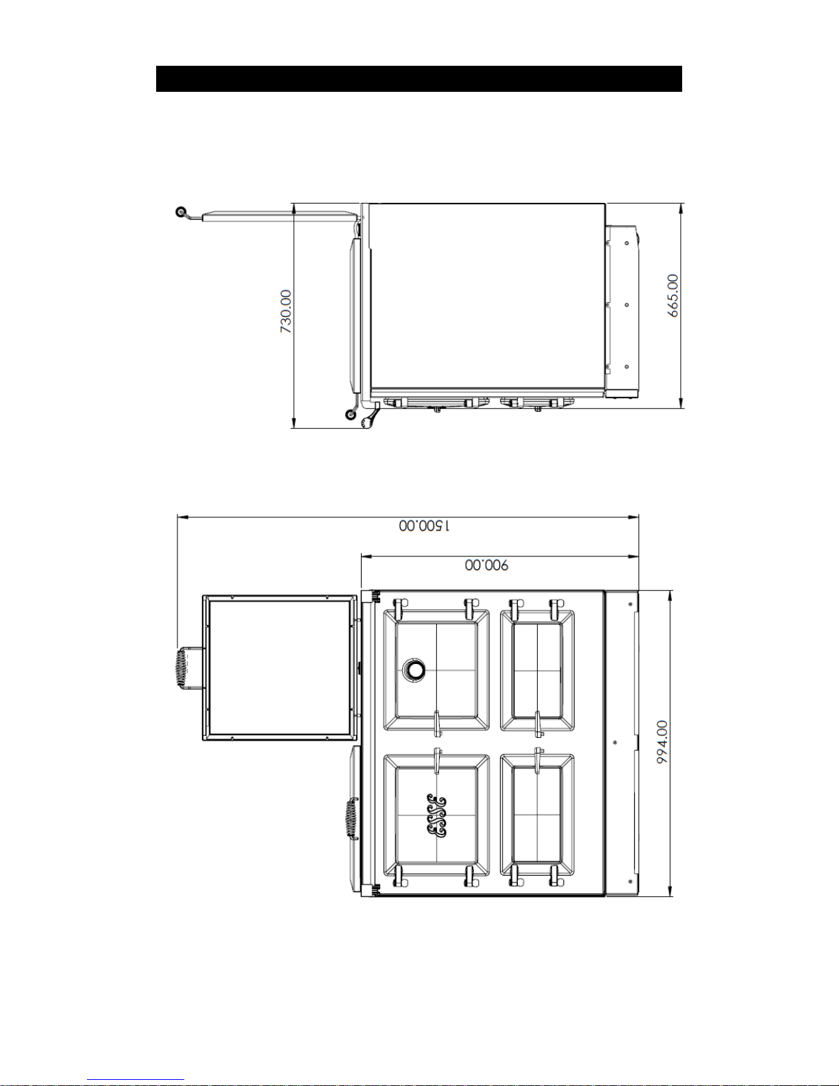
SPACING AND DIMENSIONS.
Fig. 3 990ELX Cooker Dimensions
All dimensions are in mm
Page 10
Page 10
990ELX-I02-220319
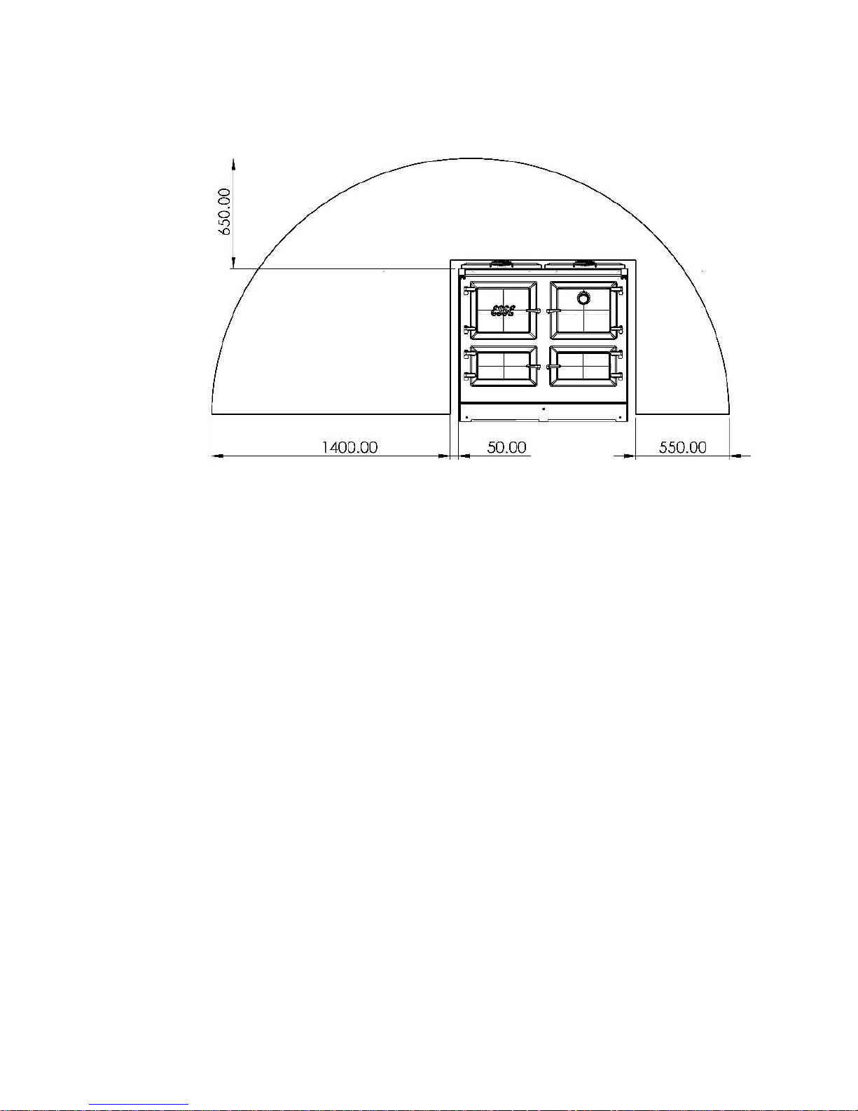
Fig. 4 990ELX Flex Reach
The above diagram shows the possible locations where the Flex of
the cooker reaches, the plug sockets for the cooker must be within
this arc.
The cooker is not to be grouted or sealed at the back or sides of the
worktop as if any maintenance is required the cooker will have to
be pulled away from the wall at the rear.
The cooker weighs 327kg and so the floor must be capable of
withstanding the load. Make sure the cooker is level, use packing
pieces if necessary.
The cooker does not require access via the side panels once it is
installed, however we do ask that a 10mm gap is provided at the
rear of the cooker and a 3mm gap between the cooker sides and
any adjoining non-combustible work surfaces that may be fitted is
provided, this is to allow for the safe removal of the top plate
should this be required at a later date. If the adjoining work
surfaces are combustible, a 20mm gap is required.
Page 11

Page 11
990ELX-I02-220319
It is not recommended that any wall cupboards are fitted above the
cooker as steam may cause damage.
Due to the hand crafted nature of the cooker all dimensions may be
±2mm.
Before using your cooker remove plastic protective
covers from inner door panels; lift up lids and hinge
covers.
Page 12

Page 12
990ELX-I02-220319
COMMISSIONING CHECKLIST
To assist with any potential guarantee claim please complete the following
information:-
To be completed by the installer.
Dealer the appliance was purchased from:
Name:
Address:
Telephone No:
ESSENTIAL information:
Date Installed
Model Description:
Serial No:
Installation Engineer:
Company Name:
Address:
Telephone No:
Commissioning Checks – to be completed and signed:
Has the use of the appliance, operation and controls
been explained?
Yes No
Instruction book handed to the customer?
Yes No
Signature:………………………………………………..
Print Name:…………………………………………………
Page 13
Page 13
990ELX-I02-220319
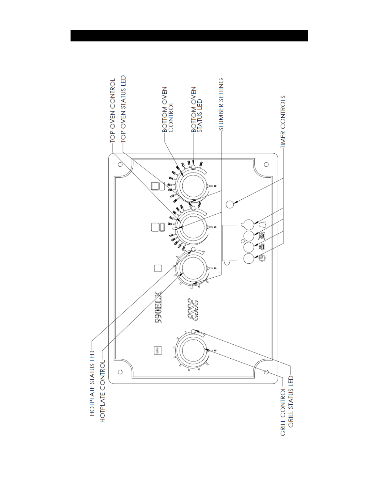
CONTROL PANEL
Fig.5: 990ELX Cooker control panel.
Page 14
Page 14
990ELX-I02-220319
TIMER
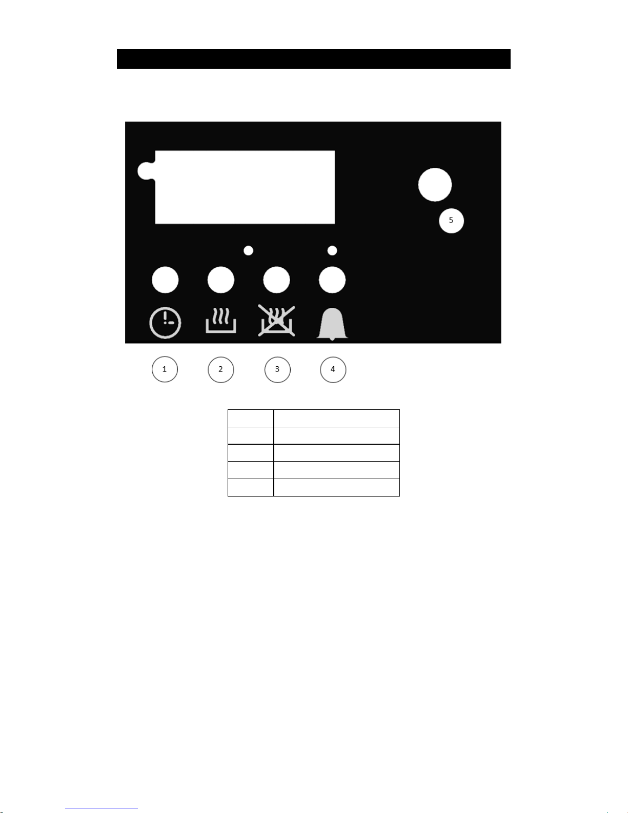
Fig.5a: Timer controls
1.
Set Time
2.
Oven on Time
3.
Oven Off Time
4.
Countdown Timer
5.
Control Dial
Setting the time
To set the time on the timer unit hold down button 1. and rotate
the control dial until the correct time is reached.
Oven control features
The timer allows the oven to rise to set cooking temperatures from
slumber at a pre-set time, and also to return to slumber at a second
set time.
To set the time for the oven to rise from slumber to cooking
temperatures carry out the following steps:
Page 15

Page 15
990ELX-I02-220319
1. Set the desired cooking temperatures using the cooker
controls as normal.
2. Hold button 2. and rotate control dial until desired time is
selected (remember to allow for oven warm up from
slumber).
The oven will remain at slumber until the desired time
is reached.
3. To set the time for the oven to return to slumber, hold
button 3. and rotate the control dial until the desired time
is selected.
Timer override
To override the timer and wake the oven or send it to slumber early
press buttons 2. and 3. together. The display will show ON or OFF
respectively when this combination is pressed.
Countdown timer
To set the countdown timer hold button 4. and rotate the control
dial until the desired time is selected (HH:MM).
To silence the alarm once the timer has elapsed press button 4.
OVENS, GRILL & SLOW COOK OVEN.
The ovens work by modulating the power between the cast iron
hotplate, the top oven, the bottom oven and the slow cook oven. If
both ovens and the hotplate are on, the cooker will share the
power to reach the selected temperatures, but if only one oven or
the hotplate is turned on, that zone will heat up more quickly.
The cooker is designed to be used in slumber mode for the majority
of the day giving off a constant background heat and can then heat
up quickly to the required cooking temperatures when required. If
the oven and hotplate elements are left at a higher setting that the
slumber settings, the cooker will put even more heat into the room.
This is also the case if the hotplate bolster lid is left up or oven
doors left ajar.
Page 16

Page 16
990ELX-I02-220319
When tested at the factory over a 24 hour period the
cooker consumed less than 0.5kwh per hour in
slumber mode at a room temperature of 18°C.
The top and bottom oven are controlled thermostatically and the
temperature markings on the controls are in °C. To switch one of
the ovens on, turn the corresponding knob clockwise to the desired
temperature. The indicator LED will glow red to show that the oven
is heating up and will glow green when the oven has reached the
selected temperature. Similarly when the control is moved to a
lower temperature the red LED will flash until the oven has reached
the selected temperature, once the selected temperature is
reached the LED will glow green again. The control shows a red
flashing LED after the oven has been switched off to indicate
residual heat.
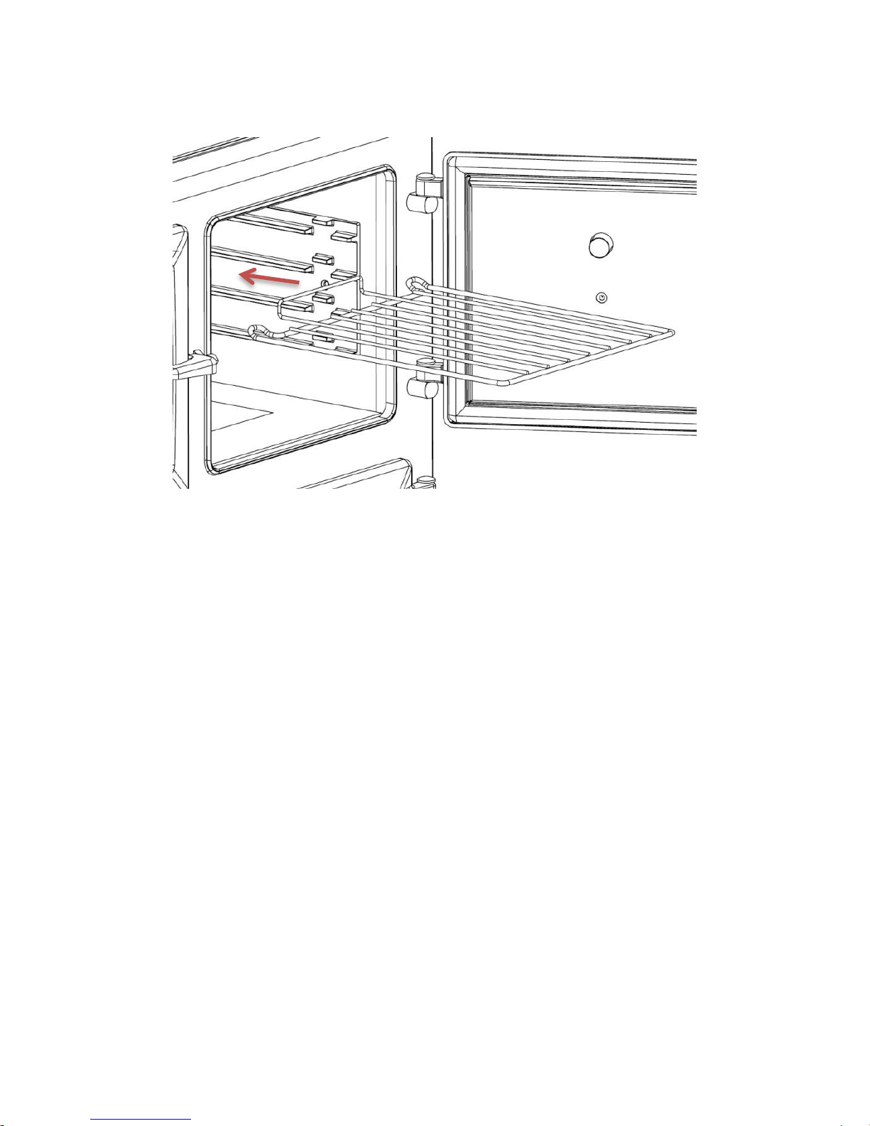
When fitting the oven shelves ensure that the shelf is orientated as
shown in fig 6. The oven shelf has two raise loops at the back that
act as a stop so as to prevent the shelf from accidentally tipping
when partially extended.
Page 17
Page 17
990ELX-I02-220319
Fig 6: Fitting an oven shelf
Top oven:
This oven has a patented 3kW wrap around element and a 3kW grill
element. The grill is a full width grill and takes priority over the
top oven control. The Top oven and grill can never be on together,
if the grill control is on at any position, then the top oven will not
work until it the grill is switched off.
The thermometer in the top oven door is only a guide to actual
oven temperature. The reading will be incorrect when the door is
or has been opened and will recover once the door is closed.
Lower oven:
This oven has a patented 3kW wrap around element and is used as
a smaller capacity, high or low temperature oven.
SAFETY POINTS:
When using the oven shelves ensure they are placed
correctly between the shelf runners and orientated as
shown in fig 6.
Always use oven gloves when removing food from either
oven or the grill.
Page 18
Page 18
990ELX-I02-220319
Grill:
The grill has a 3kW element fixed in the top of the top oven. The
grill is programmed to take priority when turned on. As such other
zones will take longer to heat up and react when the grill is
activated.
Turn the control clockwise to turn the grill on and increase the
power. The grill can take up to four minutes to reach full operating
temperature from cold. The LED indicator will show red when the
grill is turned on. The grill has a 30 minute time limit. After this
time limit has expired the grill will automatically turn off. To reset
controls after auto turn-off, it is necessary to turn the control knob
back to the ‘Off’ (0) position.
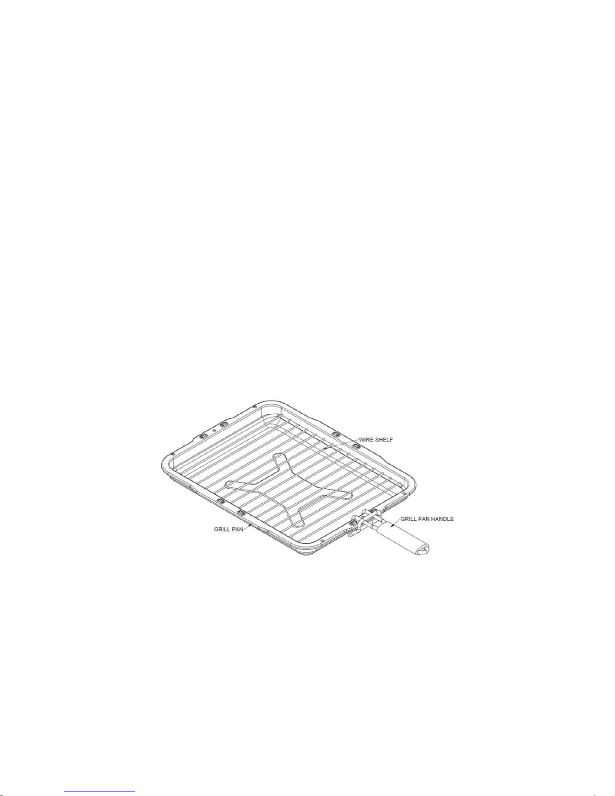
When grilling, place the grill pan onto a pre-positioned oven shelf.
The grill pan should be handled using the tool provided, locate the
tool around the rim then move to locate it in the centre of the pan.
Fig 7 Grill pan
GRILL SAFETY POINTS,
When attaching the grill pan handle. Locate the tool
around the rim then slide to locate it in the centre of the
pan.
It is not advised to leave the grill pan handle attached to
the grill pan whilst grilling, as it will become hot. Use only
when moving the grill pan,
Only operate the grill with the top oven door open.
Page 19

Page 19
990ELX-I02-220319
Ensure the oven shelf height is correctly positioned before
placing the grill pan on it.
The towel rail may become HOT after long periods of using
the grill.
Do not place towels or any other items over the towel rail
when grilling.
Slow Cook Oven:
The slow cook oven is heated automatically when either of the
ovens is switched on. The temperature is regulated to
approximately 85°C.
The slow cook oven is intended for slow cooking items such as
casseroles, joints of meat, etc. Your slow cook oven is capable of
cooking a complete meal; for instance – casserole, rice pudding and
jacket potatoes – or just warming the dishes (use only heat
resistant dishes).
Points to remember when slow-cooking:
• Preheat the oven before starting to cook.
• Do not allow dishes to touch the heating elements either side of
the oven.
• Bring casseroles, soups etc. to the boil on the hob before placing
into a suitable casserole dish for slow cooking.
• Make sure that casseroles have sufficient liquid, particularly when
cooking over a long period.
• Use lids on casseroles or foil to cover food whilst it is cooking to
retain moisture.
• Make sure all dishes will fit into the oven before preparing the
food.
• Wrap washed and pricked jacket potatoes in foil before cooking.
• Make sure that meat and poultry reach a safe temperature before
eating.
• Always thaw frozen food completely before cooking.
Your slow cook oven is also useful for warming plates and serving
dishes (use only heat resistant dishes).
Page 20
Page 20
990ELX-I02-220319
You can cook a fruitcake in the slow cook oven (if perhaps your
other ovens are in use).
You can also produce crisp, white meringues cooked in the slow
cook oven.
Timings for cooking in the slow cook oven will depend upon the
quantity and type of dish you are cooking.
Keep an eye on the food until you are familiar with the oven.
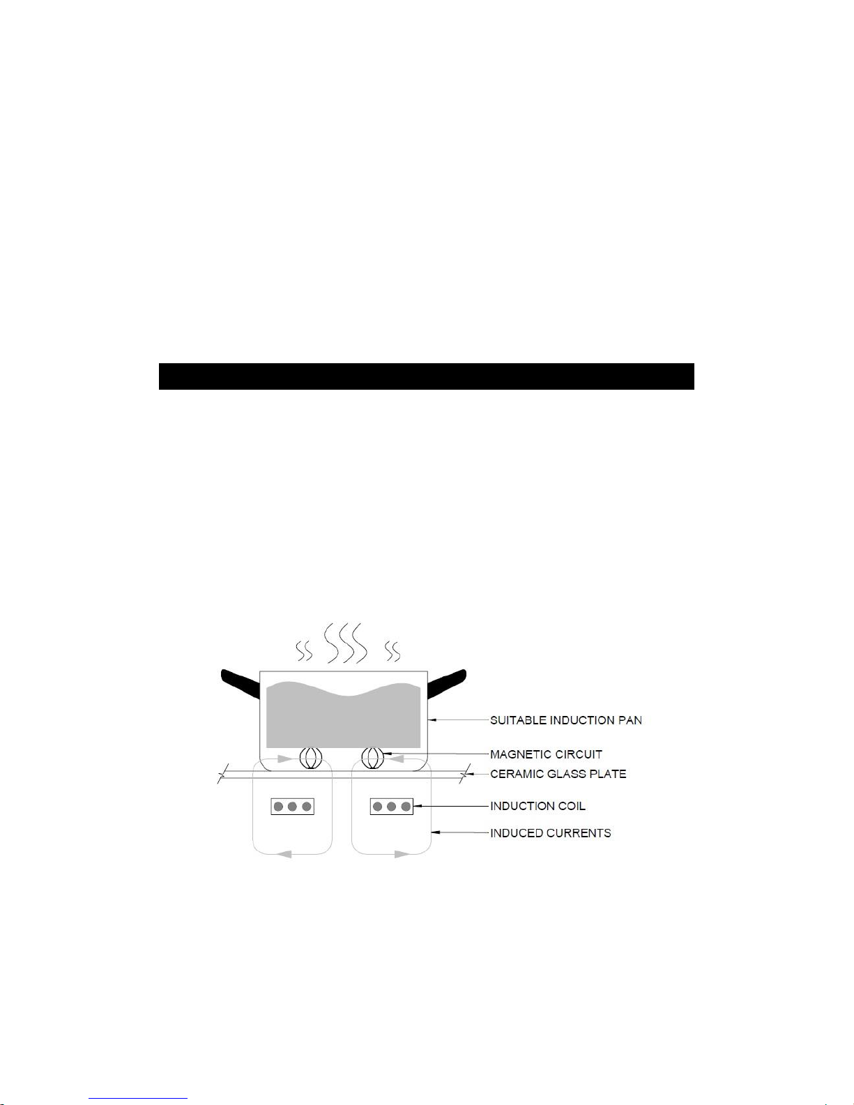
INDUCTION ZONE
Induction cooking is a safe, efficient and economical cooking
method. It works by electromagnetic vibrations generating heat
directly in the pan, rather than traditional electric hob technologies
that indirectly heat though a glass surface or metal plate. As a
result of the induction technology, the glass surface only heats up
due to heat transfer from the pan.
Fig 8 Induction Cooking
Before using the induction zone, read this guide, taking special note
of the ‘safety warnings’ section.
Page 21
Page 21
990ELX-I02-220319
Choosing compatible Cookware
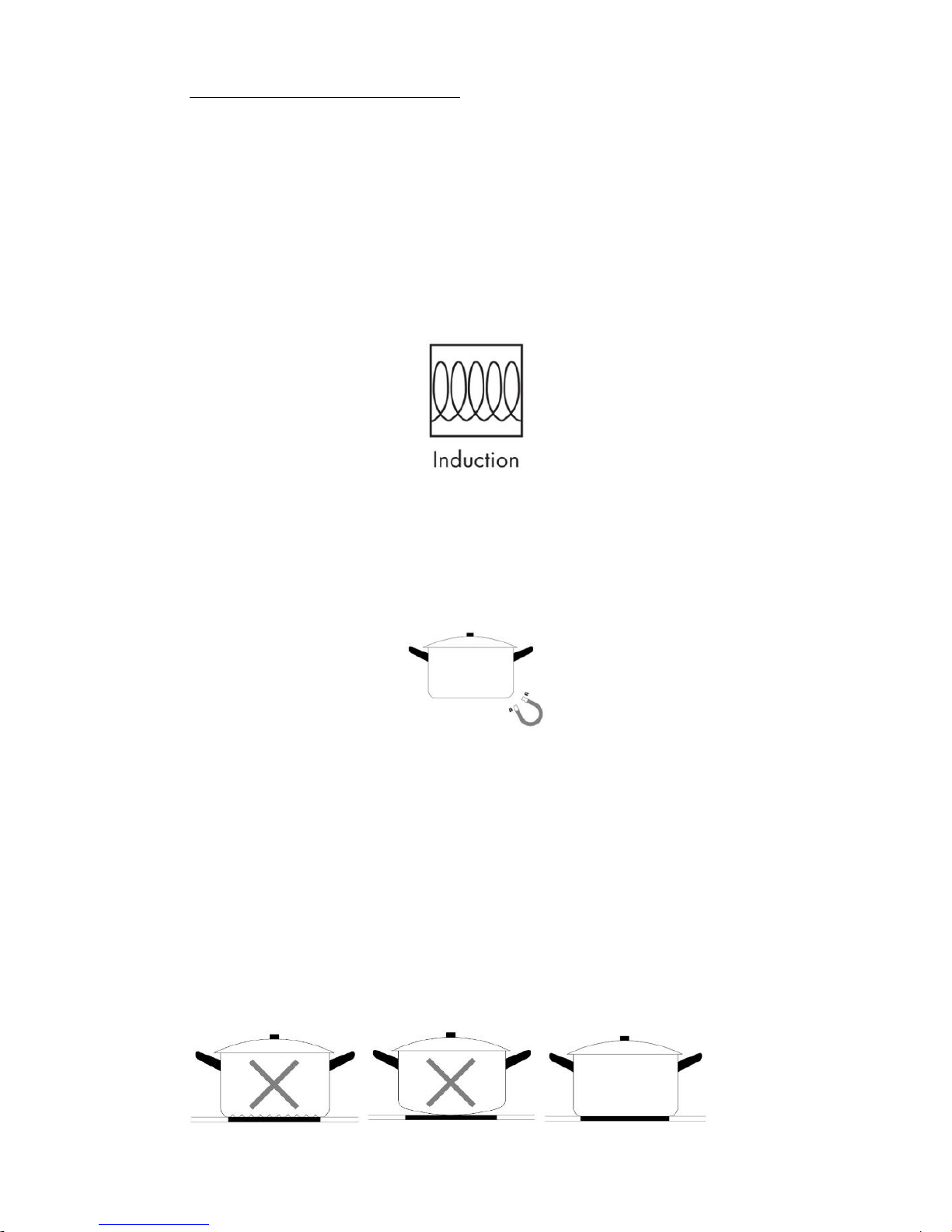
Induction hobs require cookware that is magnetic. New pans
suitable for induction cooking will be marked ‘Induction’ or with the
symbol shown in fig 9. These can be easily checked with a magnet.
Only use cookware with a base suitable for induction cooking. Look
for the induction symbol on the packaging or on the bottom of the
pan, see Fig. 9.
• Most homes will already have cast iron or stainless steel pans that
will be suitable. You can check whether your cookware is suitable
by carrying out a magnet test. Move a magnet towards the base of
the pan. If it is attracted, the pan is suitable for induction.
• Cookware made from the following materials is not suitable: pure
stainless steel, aluminium or copper without a magnetic base, glass,
wood, porcelain, ceramic, and earthenware. Some aluminium pans
available have a magnetic core inserted in the base which will make
them suitable. Esse do not recommend these pans as they have
been known to cause issues with induction hobs.
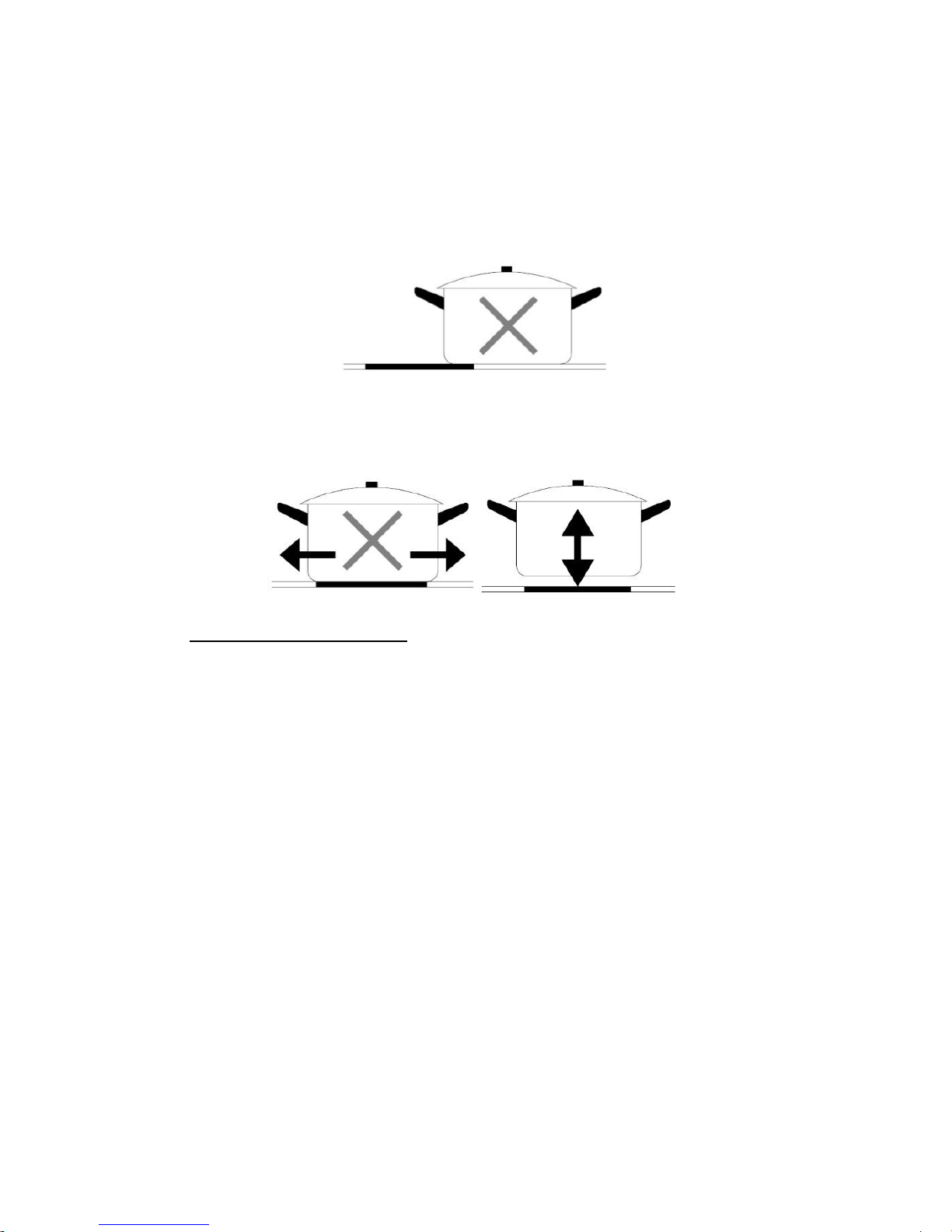
Pans should have a thick flat base. Do not use cookware with
jagged edges or a curved base.
Fig. 10
Fig. 11
Fig. 9
Page 22
Page 22
990ELX-I02-220319
Make sure that the base of your pan is smooth, sits flat against the
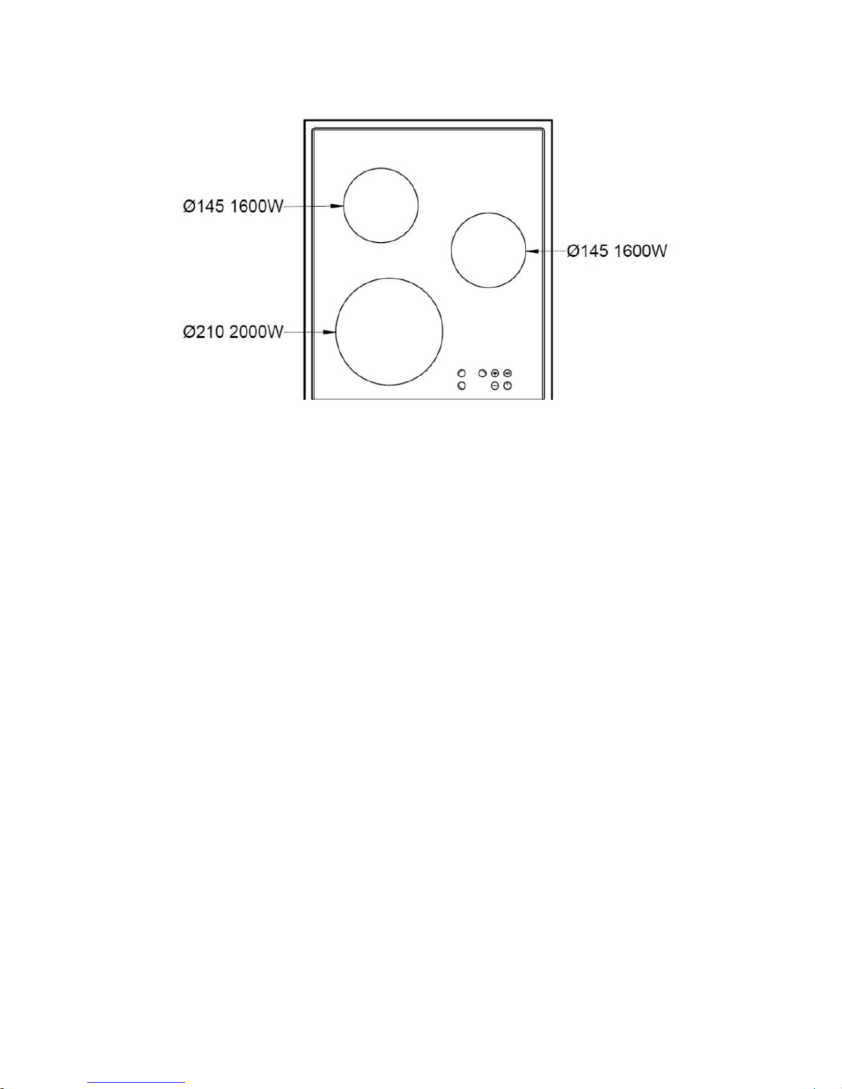
glass, and is the same size as the cooking zone. Pots less than Ø145
mm could be undetected by the hob.
You can use multiple pans on the induction zone, but one pan must
always be covering the centre of the glass.
Always lift pans off the induction hob – do not slide, or they may
scratch the glass.
Using your Induction Hob
The induction hob has 3 zones. Two are Ø145mm with 1.6kW
elements and one Ø210mm zone with a 2kW element.
Fig. 12
Fig. 13
Page 23
Page 23
990ELX-I02-220319
Fig. 14
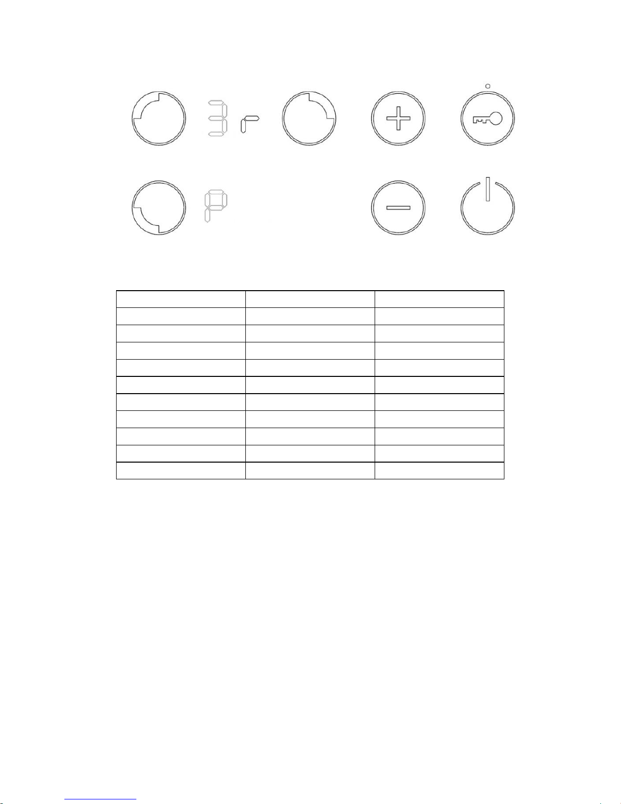
The induction is controlled via User Interface (UI) shown in Fig 15.
The set power level, any error codes and any selected functions are
displayed on the induction status display, shown Fig 15.
Each induction zone has 9 power settings, a timed full
power boost setting (P) and a timer function. The induction unit is
set to work on a 13 Amp plug and is limited to 2800w maximum.
Each zone will still work to its maximum power setting, including
the power boost functions. However each time the user tries to
increase the power, the total power level of the cooktop is
calculated. If this total power level is greater than the cooktop
power limit, the power increase is not allowed. An error beep
sounds and the zone display shows an ‘r’ for 3 seconds.
Page 24
Page 24
990ELX-I02-220319
Fig. 15
Level
Coil 210
Coil 145
Booster “P”
2000W
1600W
9
1500W
1200W
8
1300W
1000W
7
1100W
800W
6
900W
600W
5
700W
500W
4
500W
400W
3
300W
300W
2
200W
150W
1
100W
75W
User interface initial calibration.
The User Interface has implemented an initial keyboard calibration
focused to adapt the sensibility of the keys, to the final mechanical,
environmental and user conditions. Any time the Cooktop is
plugged in or there is a power failure that generates a reset in the
user interface, the first time the Key Lock is touched the sensitivity
of the keyboard is readjusted. This first touch of the Key Lock must
be done in certain conditions: Do not use gloves, Use a clean finger.
Page 25

Page 25
990ELX-I02-220319
Initial Light Conditions
When power is initially applied to the Cooktop, the touch control
conducts a calibration process for the touch keys, which requires a
low level of ambient light in the area of the touch keys.
If during this calibration process excessive ambient lighting is
detected the User Interface displays "FL" (Infrared Ambient Light
Error) and the control calibration process is suspended. In order to
rectify the process any lighting that could affect the calibration
process should be switched off (e.g. halogen cooker hood lighting).
The error will disappear when satisfactory ambient lighting is
detected and the touch control calibration procedure will now
complete satisfactorily.
Notes:
1) The "FL" error can only be generated within approximately 3s of
initial power being applied to the cooktop.
2) We recommend that the user switches off all cooker hood
lighting and any lighting directed towards the cooktop when power
is initially applied to the cooktop.
3) After the touch control has conducted its initial calibration
process, (approximately 3s) any cooker hood or other lighting can
be switched on as normal and will not affect the operation of the
touch control.
Fig. 16 Infrared Ambient Light Error
Page 26
Page 26
990ELX-I02-220319
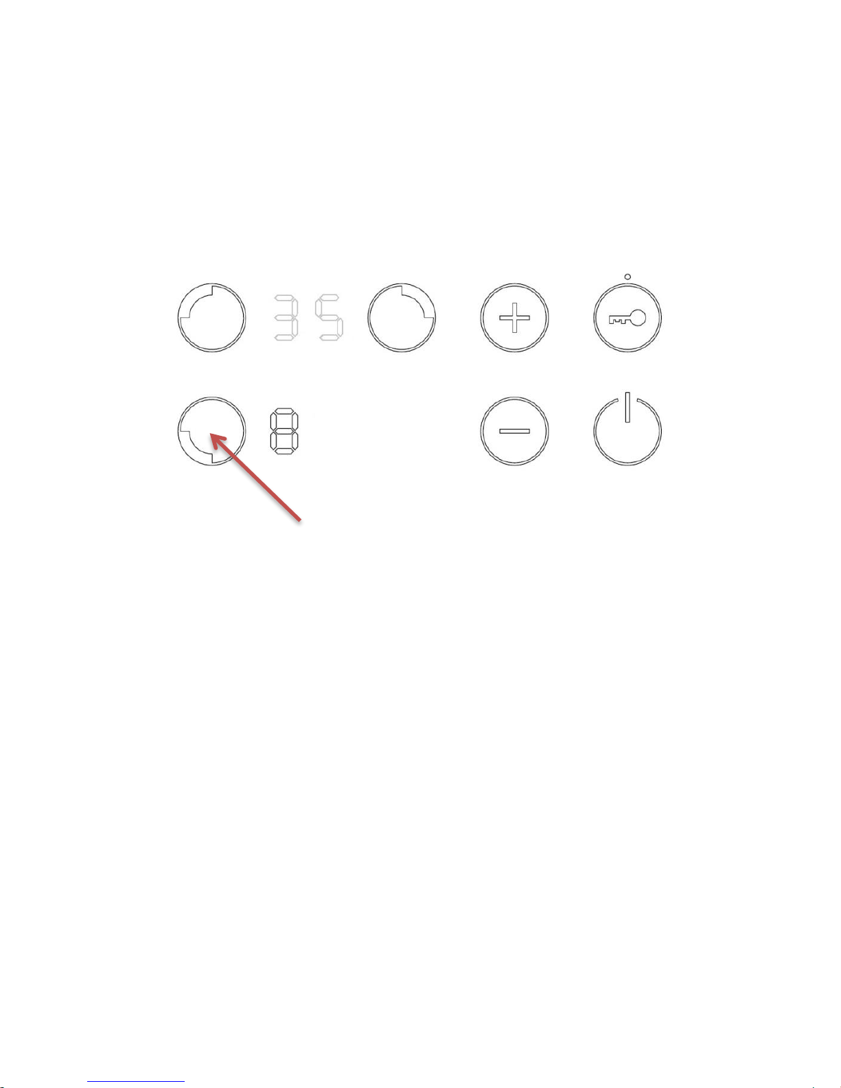
Switching On/Off the Cooktop
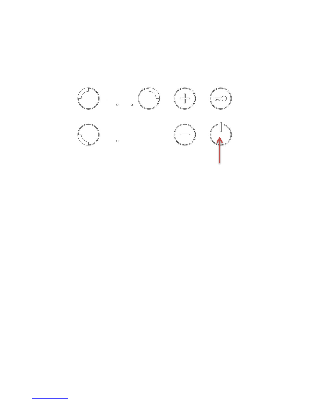
The cooktop is switched ON by touching the [ON/OFF] key for 1 sec.
A beep sounds and all the zone displays show the digit point.
Fig. 17
If the selection of a zone is not done in 10 seconds, the cooktop will
be turned off automatically.
The cooktop is switched OFF by touching the [ON/OFF] key for 1
sec. An [OFF_SOUND] sounds and all the zones are switched OFF.
The purpose of these [OFF_SOUND] is to distinguish the OFF action
over all others.
When the cooktop is OFF, after 5 sec without any error/alarm to
display and without any message to indicate (residual heat), the
control switches off the (KEYLOCK LED) in order to reduce as much
as possible the power consumption. As soon as we touch a key, the
(KEYLOCK LED) goes ON and we can continue to operate us normal
unlocking the keyboard if necessary and touching the [ON/OFF] key
to switch ON the cooktop. The (ON/OFF) key will be locked to
switch ON the cooktop if the key lock is activated (KEYLOCK LED on)
or if there is any appliance error.
ON/OFF
Page 27
Page 27
990ELX-I02-220319
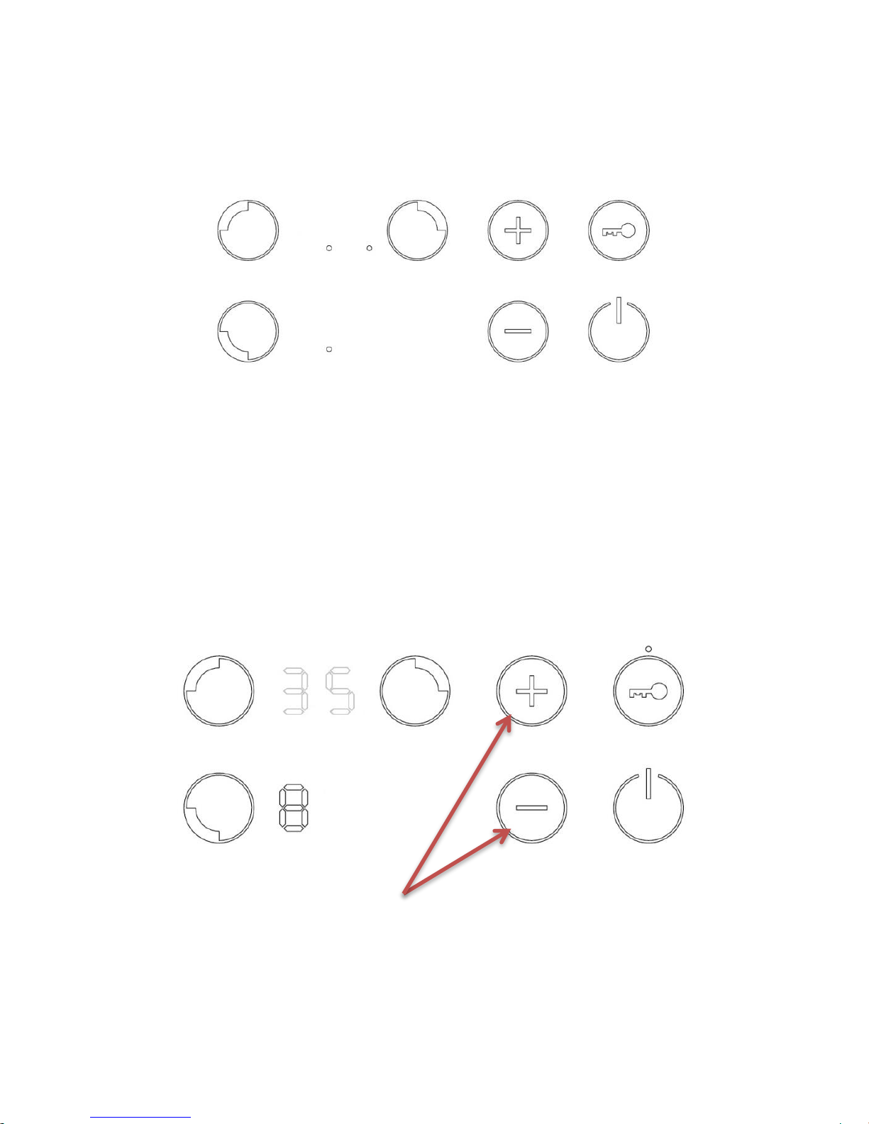
Switching On a Zone
To switch on a zone it is necessary to actuate the desired cooking
zone or zones. Once the KEY LOCK is disabled and the hob turned
ON, this is done by means of selecting the zone and then selecting
the required power level.
Fig. 18
A zone is selected by touching the zone [ZONE_SELECTION] key for
0.5 seconds, a beep sounds and the zone display shows the power
level with normal brightness.
If more than one zone is already operating, then the zones that are
not selected are dimmed.
If more than one zone is on, the zone selection will finish 10 second
after the last touch of the [-], [+] key or if another zone is selected.
If only one zone is on, the zone selection will finish if another zone
is selected.
When the zone selection is finished after 10 seconds, a beep sound
and all the zone displays that were dimed show the power levels
with normal brightness.
When the zone selection finishes, if the selected level is 0, the zone
display will be switched off
ZONE SELECTION
Page 28
Page 28
990ELX-I02-220319
When the zone selection finishes, if all the zones are off, all the
zone displays will show the digit point, waiting a zone selection.
Fig. 19
Selecting a power level for a zone
Once the zone is selected, the power level can be selected by
touching the – or + keys. In each increase/ decrease a beep sounds
and the corresponding display shows the new power level. If the
finger is held down on the key, the action is repeated twice every
second. The + key raises the cooking level to 9, whereas the - key
reduces the cooking level to 0.
Fig. 20
With the zone at power level 0, the - key raises the cooking level to
9.
POWER LEVEL KEYS
Page 29
Page 29
990ELX-I02-220319
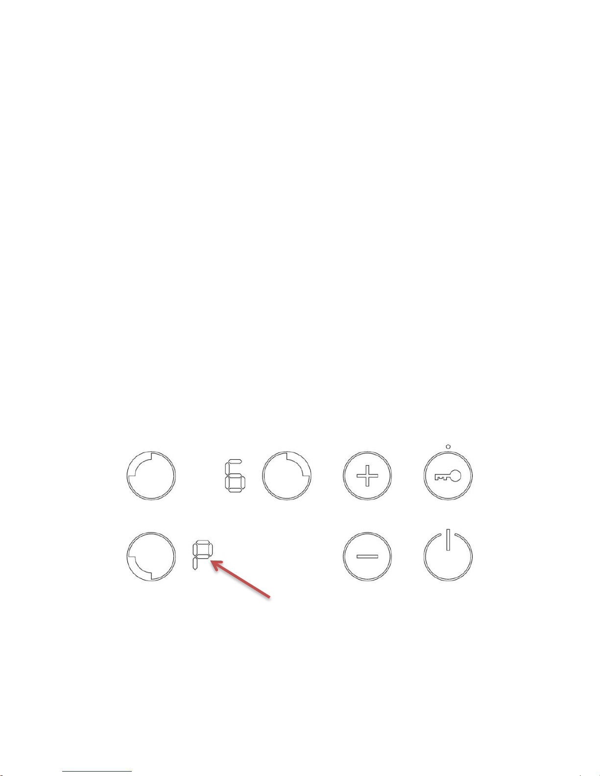
With the zone at power level 9, the + key raises the cooking level to
Booster level a beep sounds and the zone display shows “P”
With the zone at Booster level, if the + key is Touched an error beep
sounds and the cooking level doesn’t change.
With the zone at Booster level, if the - key is Touched a beep
sounds and the cook level is reduced to 9.
Fast Boil (Booster) Function
After a zone has been selected, touch the + key until level 9. To
select the Fast Boil function touch the + key again. A beep sounds
and the zone display shows “P” (see selecting a power level for a
zone)
The zone will work at maximum power level for 10 minutes. After
these 10 minutes a beep sounds and the zone will return to level “9”.
All rings or burners can be set on Power Boost at the same time.
Fig. 21
POWER BOOST
Page 30
Page 30
990ELX-I02-220319
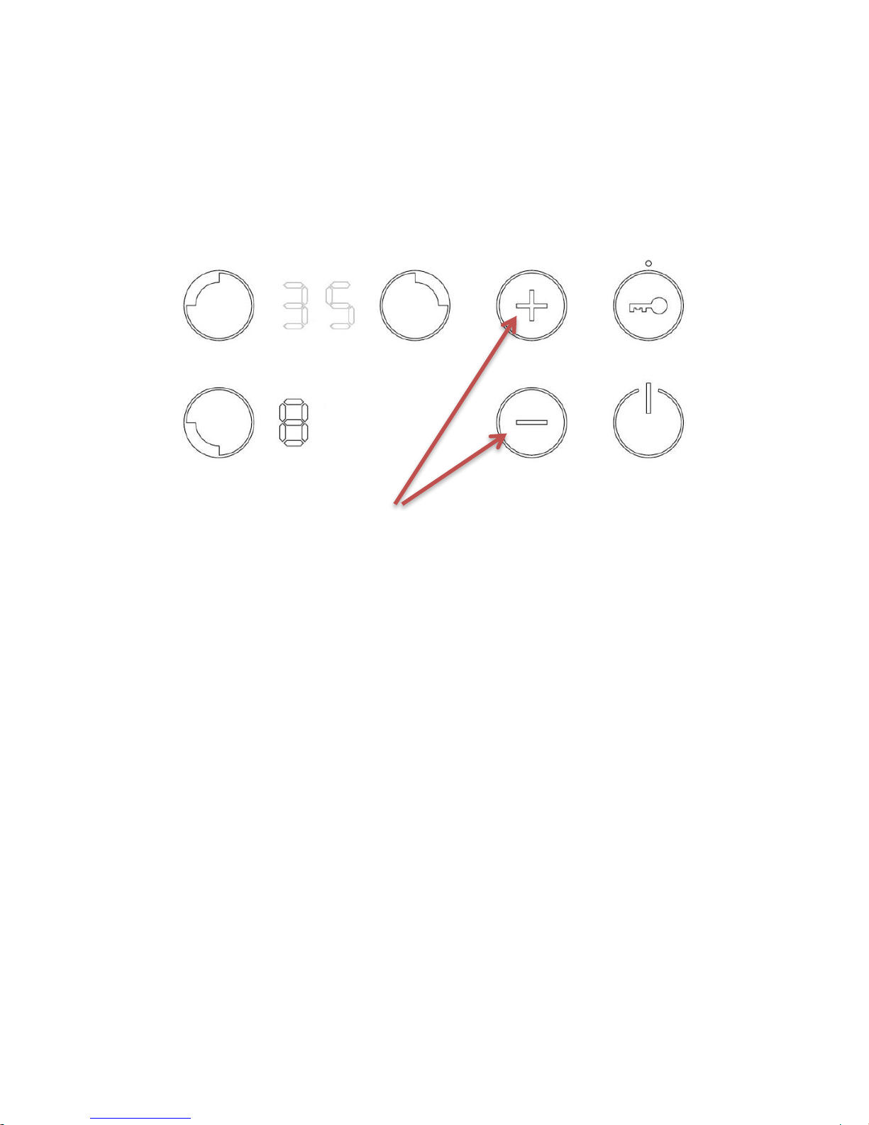
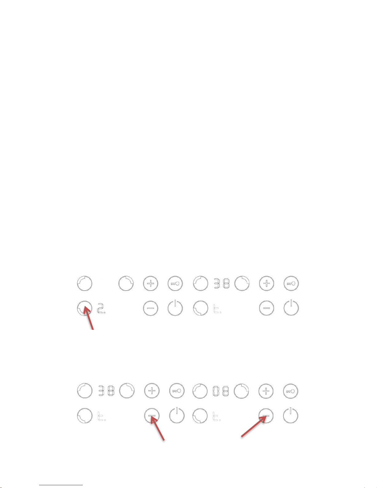
Switching Off a Zone
Once the zone is selected, the zone can be switched off by touching
the - and + keys simultaneously. A beep sounds and the
corresponding display shows “0”.
Fig. 22
Key Lock
Touching the KEYLOCK key for 1 second, the key lock function is
activated and deactivated. If the LED associated to the key lock key
is on, the keyboard is locked.
The locking function can be activated when the zones are on or
when the cook top is off. If the cook top is on, the key lock function
locks all the keys except the general ON/OFF key and the KEYLOCK.
When the cook top is OFF and the key lock function activated, all
the keys, including the ON/OFF key are locked.
The key-lock is always activated at initial power up of the control.
PRESS SIMULTANEOUSLY
Page 31
Page 31
990ELX-I02-220319
Fig. 23
Automatic Safety Shut Off
If the power level is not changed during a pre-set time, the
corresponding zone turns off automatically. The maximum time a
zone can stay on, depends on the selected cooking level
Power Level
Maximum Time ON (hours)
1
10
2
10 3 10
4
10 5 10
6
10
7
10 8 10 9 3
Operating the timer
The timer value can be selected between 1 and 99 minutes. It is
possible for the user to time all the zones at the same time at any
power level (1...P).
KEY LOCK AND LED
Page 32
Page 32
990ELX-I02-220319
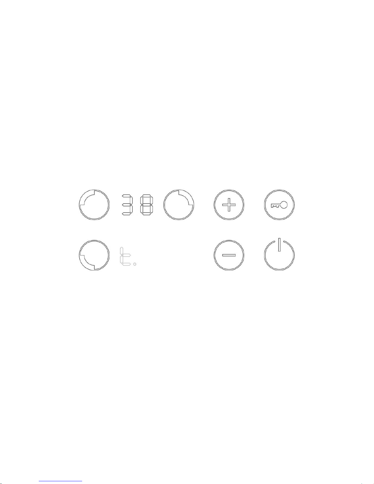
To activate a timer for any zone, first of all this zone must be
selected (touch the ZONE SELECTION key). Then, using + or - keys a
power level must be decided (for example power level 2).
Timer option is not operational if power level value is ‘0’.
When required power level is selected, touching again ZONE
SELECTION key, a beep sounds and a letter T with a dot point
appears on the zone display. The remaining time will be displayed in
the opposite part of timed zone. If timed zone is in the down part,
timed time will appear in up displays and vice-verse.
Fig. 24
When the timer is waiting a time selection, the timer value can be
selected between 0 and 99 minutes touching the + or - keys. The
remaining time will be displayed in the opposite part of timed zone.
If the + or - key is touched continuously the change speed is
increased automatically. This makes it possible to reach the desired
time setting more quickly.
If a time is not selected before 10 seconds, or if the selected time is
0 after 10 seconds of the last touch of the + or the - key, the timer is
switched off.
Page 33
Page 33
990ELX-I02-220319
Starting Timer Countdown
The countdown starts when the timer visualization is finished
touching any ZONE_SELECTION key or automatically 10 seconds
after the last touch of the + or - keys. A beep sounds and the zone
display will show the power level and the dot point showing that
the zone is timed.
Timer Countdown End
When the remaining time has run out, the timed zone is switched
off, the zone display shows a 0 blinking and the timer alarm beeps
for one minute.
The alarm will be cancelled by pressing any key of the touch
control.
Altering the Timer
To change the time for a timed zone it is a repeat of the setting
process.
Fig. 25 Select the timed zone to see the remaining time
Fig. 26 Change the time if desired
PRESS
Page 34
Page 34
990ELX-I02-220319
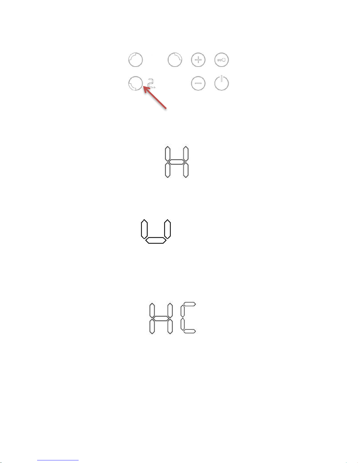
Fig 27.Accept the time
Residual Heat Display:
After turning off the induction unit, the residual heat on the
cooking element is displayed as an H.
Pot Detection:
If cookware is not detected, the ‘suspended pot’ is shown on the
Induction status display. If no cookware is recognised, the
induction zone will switch off automatically after 10 minutes.
Over Temperature:
If the induction coil or heat sink goes over temperature a letter
H and C will be displayed until the unit has reached a pre-set
safe temperature.
PRESS
Page 35
Page 35
990ELX-I02-220319
The minimum pan size for the induction zone
is Ø90mm for the Ø145mm coil and Ø130mm
for the 210mm Coil.
Heat Setting
Suitability
1-2
Delicate warming for small amounts of food
Melting chocolate, butter and foods that
burn quickly.
Gentle simmering
Slow warming.
3-4
Reheating
Rapid simmering
Cooking rice
5-6
Pancakes
7-8
Sautéing
Cooking pasta
9
Stir-frying
Searing
Bring soup to the boil
Boiling water
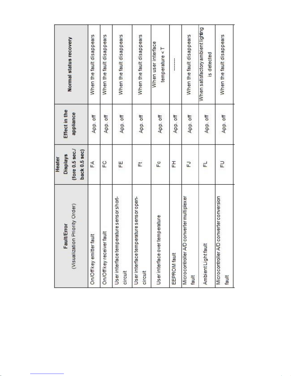
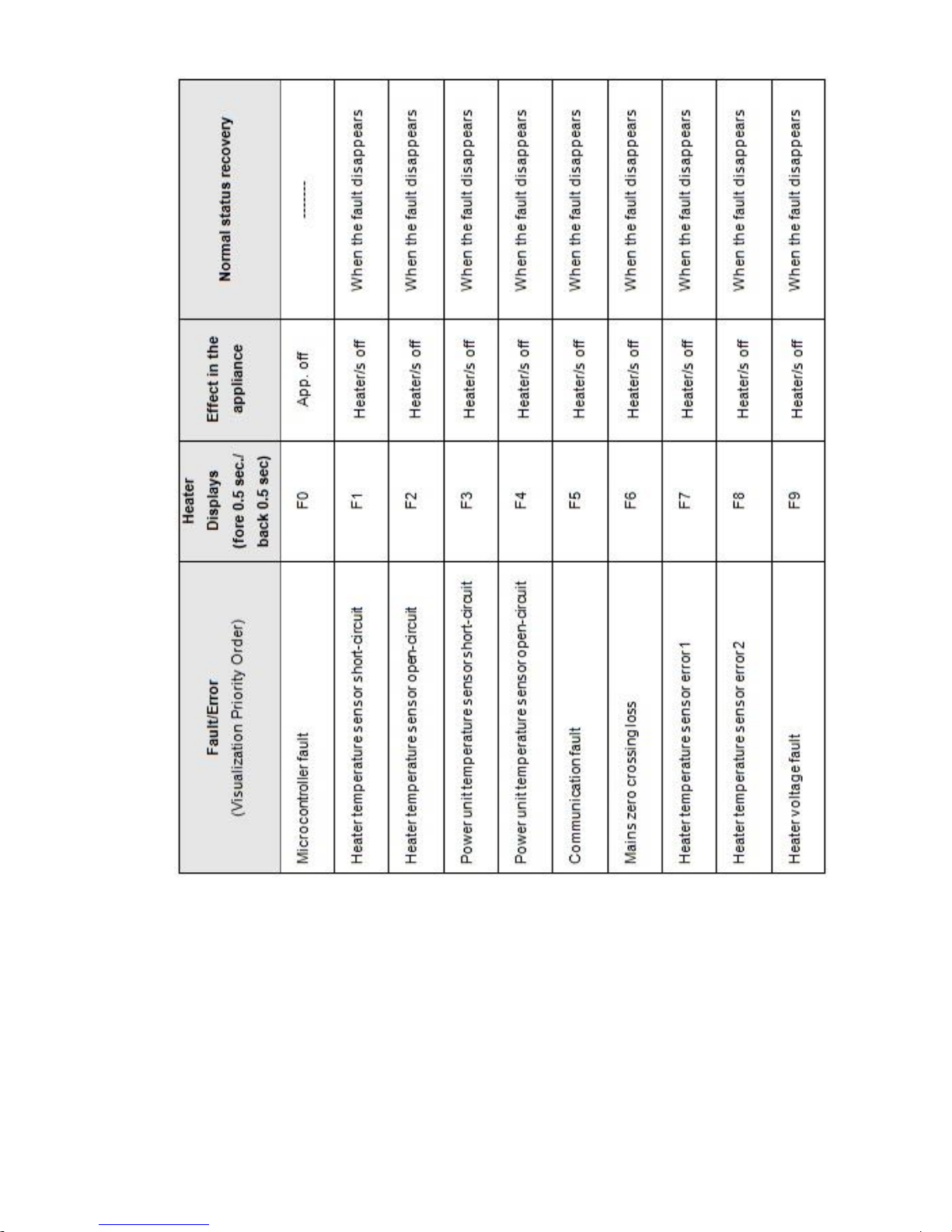
Errors/Alarms:
When an error is detected, the whole appliance or the zones are
switched off, a beep sounds (only if one or more zones are active)
and all displays show an ‘F’ letter and the error code alternately.
While in error status the keys of the corresponding zones are not
operative.
Most errors are recoverable. That is, when the cause of the error
disappears all displays are deactivated and the cooktop returns to
normal operation. If this actions does not clear the error please
contact your ESSE dealer.
Page 36
Page 36
990ELX-I02-220319
Page 37
Page 37
990ELX-I02-220319
INDUCTION SAFETY POINTS:
Page 38

Page 38
990ELX-I02-220319
If the Induction zone glass is cracked or broken the cooker
MUST NOT BE CONNECTED and no part of it may be used.
Switch off and unplug the appliance to avoid possibility of
electric shock.
Do not place or leave any magnetisable objects (e.g. credit
cards, memory cards) or electronic devices (e.g.
computers, MP3players) near the appliance, as they may
be affected by its electromagnetic field.
Never use the appliance as a work or storage surface.
HOTPLATE
The hotplate is 480mm X 450mm and has a 3kW Element.
From the OFF setting it takes approximately 5 minutes to reach
Slumber temperature, and 29 minutes from Slumber to 200⁰C.
Heat up times were checked with the heat conserving lid down and
at a room temperature of 18°C
Always use solid machined flat base pans to ensure the best contact
on the hotplate and subsequent heat transfer. Cast iron pans
usually work well.
Never use utensils with rough bases.
It is important that any spillage is dealt with before the
hob is used again, otherwise it may become baked on solid
and difficult to remove.
Always keep the hotplate cover down when the hob is not
in use to conserve energy.
Page 39
Page 39
990ELX-I02-220319
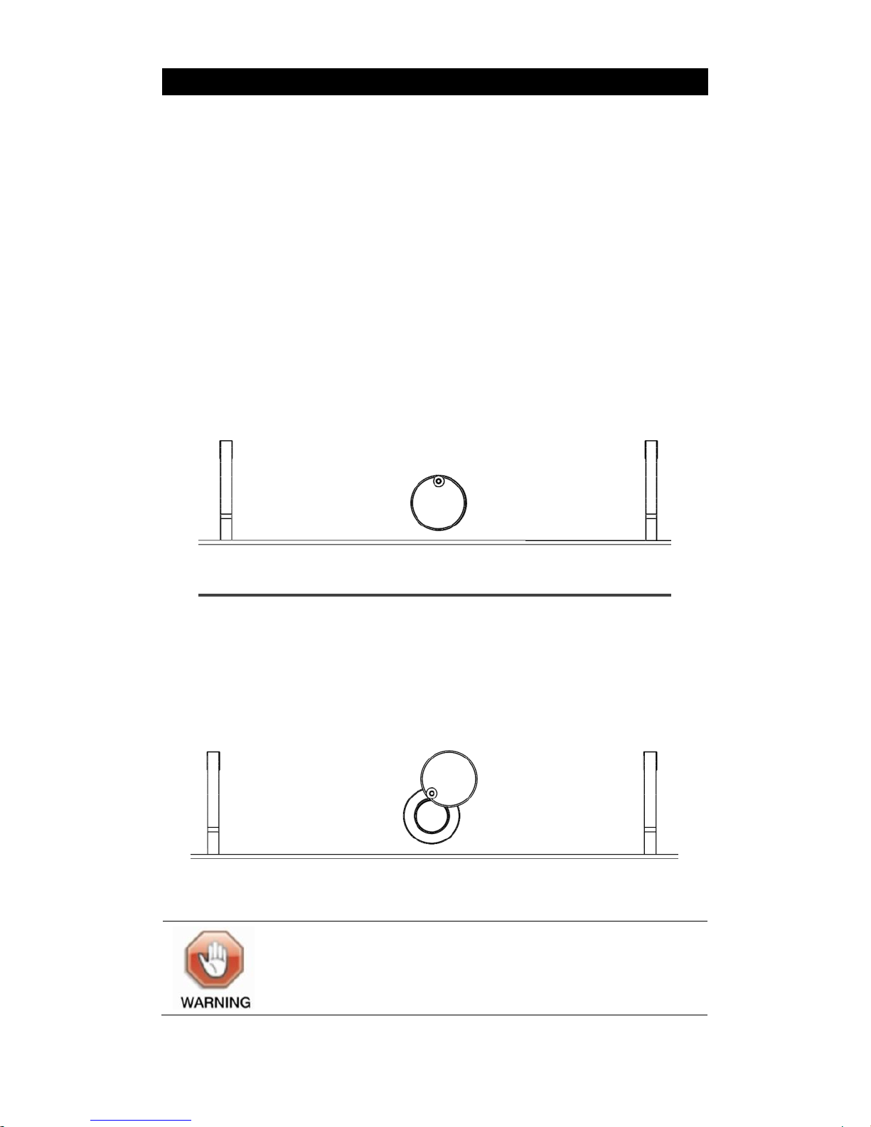
OVEN STEAM VENTS
The 990ELX cooker incorporates oven steam vents in both the top
and bottom oven.
The top and bottom oven steam vents are linked together and can
be adjusted by either opening or closing the top steam vent on the
top of the cooker.
Figure 28 shows the steam vent closed. When using the oven in
this method, condensation can form on the inside of the oven door
and run off when the door is opened.
Fig. 28 Steam vent closed.
Figure 29 shows the steam vent opened. This operation is achieved
by sliding the steam vent towards the front of the cooker.
Fig. 29 Top oven steam vent opened.
Steam is very hot and can burn.
Care should be taken and a suitable protective oven
glove or mitt be used whilst operating the oven steam
vents.
Page 40

Page 40
990ELX-I02-220319
CARING FOR YOUR ESSE COOKER.
Your Esse cooker is very easy to keep clean.
The hotplate helps to keep itself clean, by carbonising cooking spills
and splashes. Just brush off the carbon dust. For stubborn stains,
don’t be afraid to use a wire brush on the cast iron hotplate and
inside the ovens.
Splashes and spills on the painted surfaces should be wiped away as
soon as possible, using a damp soft cloth. Micro-fibre cloths are
especially good for this. Never use a cold wet cloth as the thermal
shock can cause crazing.
If spills have become baked on to the surfaces, use a soap filled pad,
not too coarse, so as to avoid scratches. DO NOT use oven cleaners.
Likewise the inner door panels and inner bolster lids can be cleaned
with a cream cleanser or for more stubborn marks, a soap filled
pad. The linings will show marks and discolour with use, but with
regular cleaning will maintain its look for longer.
The chromed bolster lids and handrail can be cleaned with a damp
soapy cloth, followed by a wet cloth, finishing by polishing with a
clean dry cloth.
Some components such as the side panels are powder coated
(painted) and nothing abrasive should be used on them. Use a soap
filled pad instead.
If the cooker is finished in the ‘Matte Black’ painted finish,
additional care must be taken not to use any chemicals or abrasive
cleaners. Use a light brush or lint free cloth instead.
If the cooker is not going to be used for an extended period of time,
we advise that the cooker be cleaned thoroughly, the ovens and
hotplate can be wiped over with a light coating of cooking oil, the
bolster lids left up and the doors left slightly ajar.
Page 41

Page 41
990ELX-I02-220319
During the life of your cooker it may be necessary to adjust the
door handles and change the door ropes. The door handles can be
adjusted using the adjustment screw on the lift up latch part of the
handle. A video on how to adjust the door handle is on the Esse TV
section of www.esse.com. Replacement door ropes can also be
purchased form www.esse.com.
EXTRACTION.
An extractor may be used with this appliance. See your local Esse
dealer or www.esse.com for details.
GUARANTEE.
Your ESSE is guaranteed against defects arising from faulty
manufacture for 2 years when supplied by an ESSE Specialist.
Upon registration of the warranty, ESSE will extend the guarantee
period to 5 years from purchase. Your details must be registered
with us by either returning the completed warranty card or by
completing registration on-line at www.esse.com. The warranty
must be registered within 1 month of installation to qualify for the
5 year warranty.
The appliance must be only used for normal domestic purposes and
in accordance with our instructions, be correctly installed and
serviced.
The guarantee does not cover:
Installation
Wear and tear
Parts deemed to be replaceable or service parts including electrical
components that may be replaced during the normal usage of the
appliance.
Surface damage caused by impact, spillage, water ingress or
condensate attack from flue or by using unsuitable fuels.
Page 42

Page 42
990ELX-I02-220319
This guarantee is personal to the original purchaser and not
transferable.
Any stove or defective part replaced shall become the Company’s
property.
INTERMITTENT USE OF YOUR COOKER
In the event of intermittent use and prolonged shutdown, we
recommend that a light coating of petroleum jelly be applied to any
damaged areas when the cooker is not in use to help keep out the
damp, in addition to following the ‘caring for your Esse cooker’
instructions.
CUSTOMER CARE
In the event you should require spare parts, please order through
your ESSE dealer or by contacting Esse via telephone (01282
813235) or our website, www.esse.com.
Should you have cause for dissatisfaction with your cooker, you
should contact your ESSE dealer, who will, in most instances, be
able to offer you immediate assistance. You will be required to give
the following details.
Your name, address and postcode.
Your telephone/contact details.
Clear and concise details of the fault.
Model and serial number of the cooker (found on the inside
panel of the bottom right hand oven door).
Purchase date (please note that a valid purchase receipt or
guarantee documentation is required for in-guarantee service
calls).
We will then check that we have an accurately completed warranty
card, if not then any work carried out may be charged.
We will assess the nature of the complaint and either send
replacement parts for your dealer to fit, send an engineer to inspect
& report, or send an engineer to repair. If the fault is not actually
due to faulty workmanship but some other cause such as misuse or
failure to install correctly, a charge will be made to cover the cost of
Page 43
Page 43
990ELX-I02-220319
the visit and any new parts required, even during the warranty
period. Home visits are made between 08.30-1700 hrs. Monday to
Friday, and are arranged for either a morning or afternoon
appointment.
Page 44

ESSE Engineering Limited, Ouzledale Foundry, Long Ing, Barnoldswick,
Lancashire
BB18 6BJ
Tel. 01282 813 235, Fax: 01282 816 876
Website and On-line Store http://www.esse.com
 Loading...