

Page 1
12/09 (PP)
INSTR.ST-515FG/i
500/525
FLUELESS CAT GAS FIRED STOVE SERIES
FLUELESS CAT GAS FIRED STOVE SERIES
FLUELESS CAT GAS FIRED STOVE SERIESFLUELESS CAT GAS FIRED STOVE SERIES
Esse Engineering Limited, Long Ing, Barnoldswick, Lancashire BB18 6BN
Tel: 01282 813235 Fax: 01282 816876 e-mail: [email protected]
Website: http://www.esse.com On-line Store: http://www.esseparts.com
INSTALLATION & SERVICING INSTRUCTIONS
(TO BE LEFT WITH THE CUSTOMER)
UK & IRELAND
GB IE
Page 2
CONTENTS
TECHNICAL INFORMATION
Important Notes Page 2 Positioning the Logs Page 7
Technical Information Page 3 Commissioning the Stove Page 7
Dimensions Page 3 Customer Briefing Page 10
Installation Page 4 Servicing Instructions Page 10
IMPORTANT NOTES
This is a High Efficiency, Flueless Catalytic, Live Fuel Effect Stove. It provides radiant and
convected warmth both efficiently and safely utilising the latest type catalytic convector
burner technology. It is recommended that it is only used as a secondary heat source.
Before installation, ensure that the local distribution conditions (identification of the type of
gas and pressure) and the adjustment of the appliance are compatible. Refer to the data
label.
The stove incorporates a thermostatically controlled gas valve, which can be adjusted by
the control knob on the front of the gas valve, located on the lower right hand side of the
stove. The stove is designed to reduce its heat output as the temperature of the room in
which it is installed rises. The main burner will automatically switch from low to off as the
room temperature continues to rise. As the room temperature cools the main burner will
switch from off to low and then adjust its input as required. There is a thermostat manual
override lever also fitted.
This stove incorporates a combustion monitoring system (ODS). It must not be adjusted or
put out of operation. If replaced then manufacturers original parts must be used.
The stove is designed to fit various types of situations as listed in the Installation Requirements.
The stove must be installed in accordance with these instructions and with the rules in force and
only used in a sufficiently ventilated space. A minimum of 100cm2 purpose provided ventilation
is required for this appliance. An openable window or louvre is also required. This appliance is
factory set for operation on the gas type, and at the pressure stated on the appliance data plate.
The room size should be a minimum of 40m3 (1412ft3) to allow adequate circulation of air and
ensure the correct operation of the stove. This volume may include adjacent spaces but these
spaces must not be separated by a door.
The stove must not be installed in a bedroom, bathroom or any sleeping area. The appliance
does not require a flue system of any type as the catalytic converter cleans the flue
products to provide a complete combustion system.
The stove must be installed by a competent person in accordance with Gas Safety
(Installation and Use) Regulations 1998 or rules in force. It is strongly recommended that a
GAS SAFE registered engineer is used for this purpose, as they are the only persons
approved by the HSE under the above regulations.
On initial light up of a new appliance, the 'newness' will burn off within the first few hours of
operation. During this period some smoke may be emitted from outlet grille, this should be
no cause for concern. Accordingly, the room should be well ventilated with all windows and
doors open during this period. All surfaces except the controls are considered to be
working surfaces.
2
GAS NATURAL GAS PROPANE
Category I2H I3P
Heat input (gross) MAX 3.3kW 3.0kW
Heat input (gross) MIN 1.6kW 1.6kW
Supply pressure 20mbar 37mbar
Burner pressure - HIGH 19.5mbar ± 0.5mbar 36.8mbar ± 0.5mbar
Burner pressure - LOW 4.6mbar ± 1mbar 10.0mbar ± 1mbar
Injector size 82/200 92/95
Gas connection 8mm O.D. tube 8mm O.D. tube
Gas consumption (high) 0.28m3/h 0.114m3/h
Oxypilot Seagas NG P441 Seagas LPG P451
Control Valve S.I.T. 0.630.700 S.I.T. 0.630.700
DIMENSIONS
Fig. 1 - 500 Series
3
NOTE
All dimensions are in millimetres
Page 3
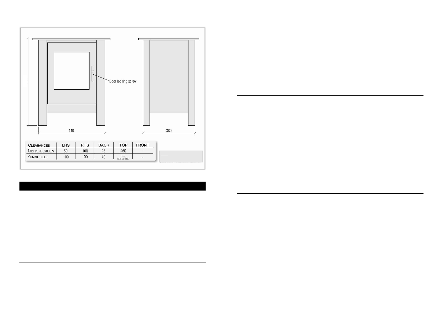
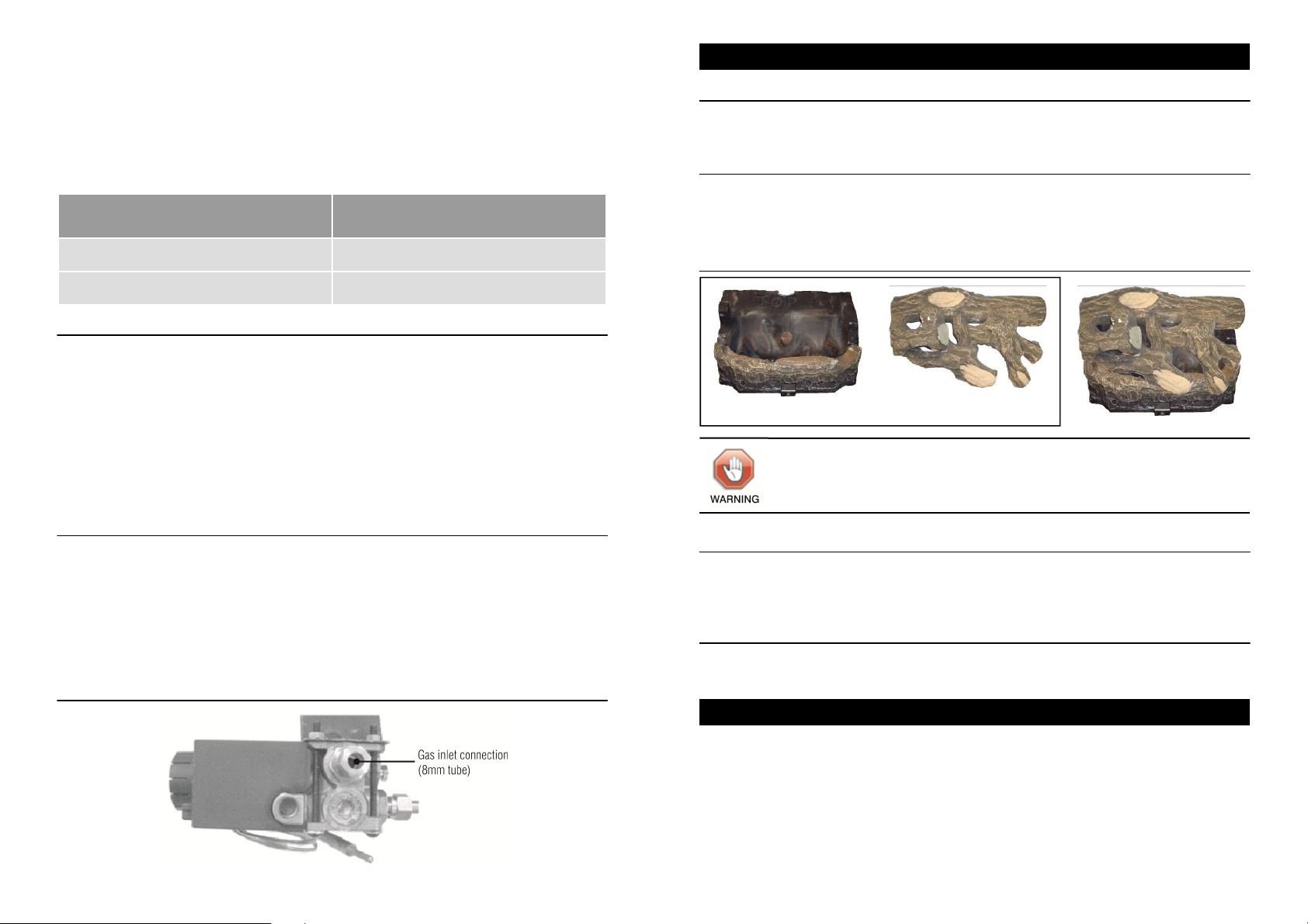
Fig. 2 - 525 Series
595
NOTE
All dimensions are in millimetres
INSTALLATION
This stove must be installed on a non-combustible hearth and be of sufficient size to
accommodate the stove. If the appliance is to be sited near a disused natural draught flue,
it is recommended that the old flue should be partially sealed off to prevent draughts,
however some ventilation will be required to prevent condensation.
In the event that the stove is sited in a disused or unserviceable fireplace served by a natural
draught flue, any existing under grate draught device should be sealed off to prevent loss
of heat or creation of draughts. The passageway into the flue should be partially sealed to
prevent excessive draughts; however some ventilation will be required in the old flue to
prevent condensation and dampness. Advice should be sought from your local building
control officer.
Room Sizing
The room size should be a minimum of 40m
3
(i.e. 14' x 14' x 7'6") to allow adequate circulation of
air and ensure the correct operation of the stove. This volume may include adjacent spaces
but these spaces must not be separated by a door.
Site Requirements
This stove may be installed in any room in a home; however there are exceptions and the
stove may not be used in bedrooms, bathrooms or shower rooms.
Installations in living rooms and conservatories are popular; however other rooms such as
kitchens, dining rooms and hallways are permitted, provided a suitable gas supply is
available, and room sizing and ventilation requirements are strictly adhered to.
The stove is designed to be versatile, and as such will operate correctly when exposed to
normal gentle draughts experienced within the home. It is not recommended, however that
the stove be installed in areas where it is likely to be exposed to persistent strong draughts,
that may be generated by outside doors or windows, air vents or other. It is recommended
that the stove should not be installed within 2 metres of any air vent.
Clearances to Non-Combustibles
Non-combustible surfaces are defined as brick, metal, marble, concrete etc. and also a
number of manmade materials impervious to flame. If in doubt, refer to the material
manufacturer for further information before proceeding with installation.
Clearances to the sides of the stove is 50mm (2ins), however clear and easy access to the
controls located on the lower right hand side of the stove must be allowed for, and we
would therefore recommend that at least 100mm (4ins) be allowed. Clearance to the front
of the stove is 500mm (2ft). Care must be taken that no brickwork or other incombustible
material protrudes into the area immediately around the base of the stove or area underneath
the stove in a way that is likely to affect natural air flow into or around the appliance.
For th e 5 00 s e ries th e ba ck of the stove may be installed direc t l y aga i ns t a
non-combustible wall. For the 525 stove it is recommended there should be a minimum
clearance of 25mm (1in) between the top plate and a non-combustible wall.
Installation into 'inglenook' type fireplaces is acceptable. However it is recommended that
there is at least 460mm (18ins) clearance above the outlet grille.
Clearances to Combustible Materials
Combustible materials are defined as wood, fabrics, or other materials likely to combust if
exposed to flame. Generally, any material, which is likely to discolour, melt or misshape
when exposed to moderate heat, should be considered as a combustible material or
surface. Any fire surround to be used in conjunction with this stove should be rated at a
minimum of 100°C.
Clearances to the sides of the stove are 100mm (4ins) but curtains, drapes and other
fabrics are not permitted within a distance of 500mm (20ins) of the stove sides and back.
No such materials are permitted directly above the stove regardless of distance. Clearance
to the front of the stove is 1000mm (39ins). Clearance to the rear of the stove is 70mm
(2¾ins) from the back of the top casting.
It is not permitted to install the stove onto carpet, rugs or fabric materials of any kind.
Installations into 'inglenook' type fireplaces is acceptable, provided adequate consideration
is given to any wooden cross-members and such like.
A combustible shelf may be fixed to the wall above the stove, provided that it complies with
the dimensions given on page 6. The shelf depth is measured from the wall BEHIND the
stove.
4
5
Page 4
The shelf depth may be greater than 150mm (6ins) up to a maximum of 457mm (18ins) but
the height must also be increased accordingly. An increase in height of 25mm is required
for every 12.5mm of additional shelf depth. For shelves that are too low, protective devices
can be used such as metal heat deflectors, but it must be assured that the shelf does not
reach an unacceptable temperature before relying on such a solution.
As with all heating appliances, any decorations, soft furnishings, and all coverings (i.e.
flock, blown vinyl and embossed paper) positioned too close to the appliance may
discolour or scorch.
Maximum depth of the shelf
FROM THE WALL BEHIND THE STOVE
150mm (6") 330mm (13")
457mm (18") 940mm (37")
Minimum distance from top of stove to
underside of shelf
Ventilation
A minimum of 100cm
3
purpose provided ventilation is required for this stove. An openable
window or equivalent is also required. The requirements of any other flued appliance
operating in the same room or space must be taken into consideration when assessing
ventilation.
Any ventilation fitted must comply with BS5871
BS5871 and BS5440
BS5871BS5871
BS5440 part 2. Ventilation fitted under,
BS5440BS5440
or within immediate vicinity of the appliance must not be used as it may adversely affect
performance of the ODS system. The stove MUST NOT be installed in a bedroom,
bathroom or any sleeping area.
For Republic of Ireland, see relevant rules in force.
Gas Connections
The gas connection to the stove is located at the right hand side of the stove underneath
the stove casting (see Fig. 3). The gas supply may connect to the stove over the hearth or
by concealed connection below the stove. Concealed pipes should not be routed through
walls without being protected by sleeving or conduit. No more than 1.5m of 8mm pipe must
be used to avoid unnecessary pressure drops.
If a concealed gas connection is to be made, the supply pipe should always be sleeved
through walls and floors using the shortest possible route.
Fig. 3 - Control Valve
POSITIONING THE LOGS
500 Series Stove
Remove the door locking screw (if fitted) located behind the spinner (Fig. 1) and open the
stove door.
525 Series Stove
Remove the door locking screw (Fig. 2)
Position the log cluster on top of the backboard and front log as shown in Fig. 4
Fig. 4 - Positioning the Logs
FRONT LOG & BACKBOARD LOG CLUSTER
500 Series Stove
Close the stove door and replace the door locking screw (if fitted) and spinner. Under no
circumstances should the stove be operated with the door open, without the door attached
or the glass damaged.
525 Series Stove
Close the stove door and replace the door locking screw. Under no circumstances should
the stove be operated without the door attached or the glass removed or damaged.
COMMISSIONING THE STOVE
The stove is fitted with a pilot light which is also an oxygen depletion sensor (ODS), piezo
spark, flame sensing device and thermostat. The control is located behind the right hand
foot of the stove. The pilot light is located centrally behind the front log piece.
Should the stove be extinguished for any reason wait 3 minutes before re-ignition is
attempted. A safety interlock prevents re-ignition of the pilot flame until the thermocouple
has cooled sufficiently
Connect a suitable pressure gauge to the burner pressure test point (Fig 7).
Do not add any extra logs or coals.
6
7
Page 5
a) Lighting the Pilot
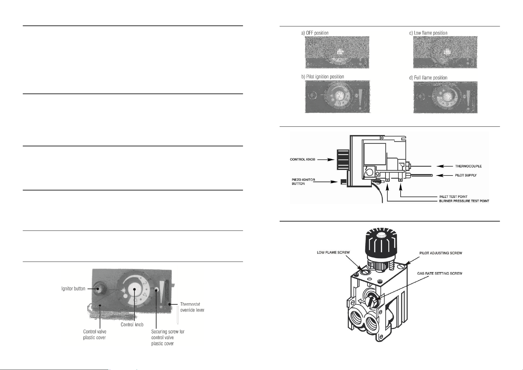
1. Turn control knob to PILOT IGNITION POSITION (Fig. 6b).
2. Press control knob downwards and hold it in.
3. Press ignitor button fully downwards to obtain a spark. Repeat until the pilot lights.
4. Continue to hold the knob in for about 10 seconds after the pilot ignites. Release the
control knob.
If the pilot goes out repeat steps 2, 3 and 4.
b) High Setting
Push the thermostat lever down to the 'thermostat position' (Fig. 5). Turn the control knob to
FULL FLAME POSITION (Fig. 6d). Check that the HIGH burner setting pressure is in
accordance with that given in the TECHNICAL INFORMATION section. The pressure is
factory set and should not require adjustment, but if necessary adjust the HIGH FLAME
SCREW (Fig. 8). For access to this remove the control plastic cover (Fig. 5).
c) Low Setting
Turn the control knob to LOW FLAME POSITION (Fig. 6c) which is just before the snap off
position. Check that the LOW burner setting pressure is in accordance with that given in the
TECHNICAL INFORMATION section. The pressure is factory set and should not require
adjustment but if necessary adjust the LOW FLAME SCREW (Fig. 8).
d) Turning the Stove OFF
From any heat setting depress control knob fully and turn clockwise to PILOT POSITION
(Fig. 6b). Disconnect the pressure gauge; replace the test point sealing screw and test for
gas soundness.
e) Turning the Pilot OFF
From any heat setting or the PILOT POSITION depress control knob fully and turn
clockwise to OFF position.
Fig. 5 - Controls on 500/525 Valve
Fig. 6 - Operating the Valve
Fig. 7 - Control Valve (side view)
Fig. 8 - Control Valve Connections and Rate Screws
8
9
Page 6
CUSTOMER BRIEFINGS
Advise the customer how to use the stove.
Point out that the operating procedure is in the User Instructions.
Explain to the customer that the stove has a flame sensing device and oxygen depletion
monitoring system.
Point out the explanation of this system in the User Instructions.
Advise that if the monitoring system repeatedly shuts off the stove, it should be switched off
and a specialist consulted.
Advise that if the stove goes out for any reason, wait at least 3 minutes before re-lighting.
Advise the customer that due to newness of materials the stove may give off a smell for a
period of time after commissioning and that this is quite normal and any odours should
disappear after a few hours operation.
Stress that no extra coals or logs must be added over and above those supplied with the
stove and that any replacement parts must only be authorised ESSE spares.
Recommend that the stove is regularly serviced at least once a year by a qualified person.
Hand these Instructions and the User Instructions to the customer.
SERVICING INSTRUCTIONS
The stove is fitted with a pilot light and flame-sensing device which is also an oxygen
depletion sensor (O.D.S.). This is not adjustable and must not be put out of action. If any
parts of this system require replacement only original manufacturers parts must be used.
The following servicing procedure should be carried out regularly and only by a qualified
person.
1. Ensure that the fire is turned off and cold.
2. Remove the logs, backboard and front log piece in the reverse order to that
described in POSITIONING THE LOGS section on page 7.
3. Carefully remove any deposits of dirt, lint etc. from the burner flame strip, tray,
aeration holes and pilot assembly with a soft brush.
4. Clean the pilot aeration 'hole'.
5. Inspect the catalyst for signs of damage and dirt. The expected life of the catalyst is
in excess of 11,000 hours (10 years of normal use). After this time the catalyst
should be replaced. If there are any deposits of dirt or soot on the catalyst clean
with a soft brush and a vacuum cleaner.
6. Due to the intense temperatures reached in the stove, some surface cracks may
appear on the ceramic components. This is quite normal and will not affect the safe
operation of the stove. Replace the front log piece, backboard and logs as described
in POSITIONING THE LOGS section on page 7.
7. Check the high and low burner setting pressures as described in COMMISSIONING
THE STOVE section on page 7.
8. Check the safe operation of the appliance.
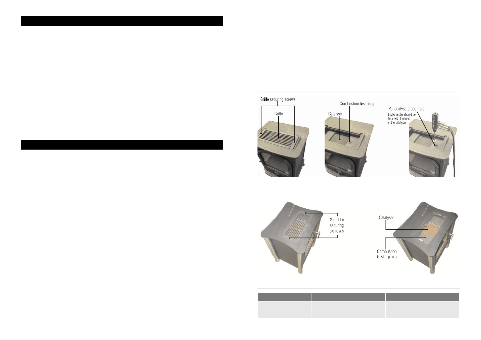
9. With the stove cold remove the grille and the combustion test plug (Fig. 9). Light the
stove on HIGH and after 15 minutes check the combustion performance is in
accordance with the table on page 11.
10
10. If the CO figures are more than given in the table ('below the catalyser') this
suggests that either the aeration holes on the burner require cleaning or the
ceramic fuel bed components are incorrectly placed. Turn OFF the appliance and
investigate and correct.
11. If the CO figures are more than given in the table ('above the catalyser') this
suggests that the catalyser is due for changing.
12. Check that the purpose provided air vent is not obstructed.
Should any replacement components be requested they must only be authorised ESSE
spares.
Fig. 9a - 500 Series
Fig 9b - 525 Series
Fig. 10 - CO and CO
Above Catalyser Below Catalyser
CO ppm Less than 10 Less than 300
CO2 % Approx. 3.5 - 4.5 Approx 3.5 - 4.5
emissions
2
11
 Loading...