

Page 1

Wall-mounted Gas Fires
41 & 48 Landscape
INSTALLATION,USER & SERVICING INSTRUCTIONS
(TO BE LEFT WITH THE CUSTOMER)
UK & IRELAND
UK
IE
Page 2

Page 2
41L48L-I01-270318
INSTALLATION INSTRUCTIONS
CONTENTS
Important Notes
Page 2
Commissioning the Heater
Page 15
Technical Information
Page 4
Customer Briefing
Page 22
Dimensions
Page 5
Commissioning Checklist
Page 23
Installation
Page 5
Servicing Instructions
Page 24
IMPORTANT NOTES
This is a high efficiency, flueless catalytic, live flame effect
heater.
It provides
radiant
and convecte
d heat,
both efficiently
and safely ut
ilising
the latest
type of
catalytic
convector burner technology
. It is reco
mmended only as a secondary
heat source.
Before installation, ensure
that the local distribution conditions identification o
f
the type of
gas and pressure and the adjustment of
the heater are compatible
.
Refer
to the d ata label
, visible when the front is removed (
Figure 3).
If
the heater is
to be
used for Propane,
the M8 aeration
screw should
be fitted. If
the heater is to be used for Butane, or
Butane/Propane mix or Natural Gas this
aeration
screw
MUST NOT BE FITTED (
Figure 10).
This heater has either a manually controlled
gas valve which
can be adjusted
by the control knob
on the front of
the
gas valve, located
on the lower right
hand side
of
the heater behind
the front panel
or a remote co n trolled
valve operated via a handset.
This heater incorporates
a combustion monitoring
system
(ODS).
It
must
not be
adjusted or put out of operation.
If replaced
then manufacturers original parts
must
be used.
The heater is designed to
fit various
types of situations
as listed in
the Installation
Requirements.
This heater must be installed in accordance with these instructions and with the rules in force and
only used in a sufficiently ventilated space. A minimum of 100cm2 purpose provided ventilation is
Page 3

Page 3
41L48L-I01-270318
required for this appliance. An openable window or equivalent is also required. The room size should
be a minimum of 30m3 (1059ft3) for the 41 Landscape model and a minimum 40m3 (1412ft3) for the
48 Landscape model. This volume may include adjacent spaces but these spaces must not be
separated by a door.
The heater must not be installed in a bedroom, bathroom or any sleeping area.
Additionally for LPG, the heater must not be used in cellars or basements. The heater does not
require a flue system of any type as the catalytic converter cleans the flue products to provide a
complete combustion system.
The heater
must
be installed
by a
competent person in accordance with Gas
Safet
y (Installation and
Use) Regulations 1998 or rules in force. In particular,
as
the
gas supply pipe may we
ll
be concealed within
a wall, attention is
drawn to
regulation 19 ‘Enclosed Pipes’.
It is strongly reco
mmended that
a GAS SAFE
registered engineer is used for this purpose,
as
they are the only persons
approved
by the HSE under the above regulations.
On initial light
up of
a new heater, the ‘newness’ will
burn
off within
the first few
hours of operation. During this period
some smoke
may be emitted from
the
outlet grille, this should be no
cause for concern. Accordingly, the room should
be well ventilated with all windows and doors
open during this period.
All surfaces
except the controls
are considered
to be working surfaces
.
Page 4

Page 4
41L48L-I01-270318
TECHNICAL INFORMATION
Table 1 41 Landscape Technical Data
GAS
NATURAL GAS
(G20)
PROPANE
(G31)
LPG
Butane (G30)/Propane (G31)
CATEGORY
I
2H
I3P
I
3
B/P (30)
HEAT INPUT (GROSS)
MAX
2.6Kw
2.6kW
2.6kW
HEAT INPUT (GROSS)
MIN
1.7Kw
1.9kW
1.75kW
SUPPLY PRESSURE
20 mbar
37mbar
30mbar
BURNER PRESSURE
HIGH
19.8 mbar
±0.5 mbar
36.4 mbar
±0.5 mbar
27.0 mbar
±1.0 mbar
BURNER PRESSURE
LOW
10.5 mbar
± 0.5 mbar
23.0 mbar
±0.5 mbar
11.5 mbar
±0.5 mbar
INJECTOR SIZE
3/160
7/75
7/75
GAS CONNECTION
8mm O.D. Tube
8mm O.D. Tube
8mm O.D. Tube
GAS CONSUMPTION
(HIGH)
0.23m³/h
0.1m³/h
0.076m³/h
OXYPILOT
SEAGAS NG 441
SEAGAS LPG 451
SEAGAS LPG 451
Table 2 48 Landscape Technical Data
GAS
NATURAL GAS
(G20)
PROPANE
(G31)
LPG
Butane (G30)/Propane (G31)
CATEGORY
I2H
I3P
I3B/P (30)
HEAT INPUT (GROSS)
MAX
3.5kW
3.5kW
3.5kW
HEAT INPUT (GROSS)
MIN
2.3kW
2.3kW
2.3kW
SUPPLY PRESSURE
20 mbar
37 mbar
30 mbar
BURNER PRESSURE
HIGH
19.5 mbar ± 0.5
mbar
36.8 mbar ± 0.5
mbar
29 mbar ± 1.0 mbar
BURNER PRESSURE
LOW
9.2 mbar ± 0.5
mbar
18.4 mbar ± 0.5
mbar
13.1 mbar ± 0.5
mbar
INJECTOR SIZE
7/220
7/100
7/100
GAS CONNECTION
8mm O.D TUBE
8mm O.D TUBE
8mm O.D TUBE
GAS CONSUMPTION
(HIGH)
0.31m3/h
0.13m3/h
0.078m3/h
OXYPILOT
SEAGAS NG 441
SEAGAS LPG 451
SEAGAS LPG 451
Page 5

Page 5
41L48L-I01-270318
DIMENSIONS
Figure 1 41 & 48 Landscape Firewall Dimensions
INSTALLATION
This heater is designed to be wall mounted. The wall should be reasonably flat and of a
sufficient size to accommodate the heater (see Figure 1). If the appliance is to be sited
near a disused natural draught flue, it is recommended that the old flue should be
partially sealed off to prevent draughts however some ventilation will be required to
prevent condensation.
ROOM SIZING
The room size should be a minimum of 30m3 (e.g. 12’ x 12’ x 7’6) for the Widescreen
41” model and a minimum of 40m3 (e.g. 14’ x 14’ x 7’6) for the Widescreen 48” to allow
adequate circulation of air and ensure the correct operation of the heater. This volume
may include adjacent spaces but these spaces must not be separated by a door.
SITE REQUIREMENTS
Page 6

Page 6
41L48L-I01-270318
This heater may be installed in any room in a home: however there are exception and
the heater may not be used in bedrooms, bathrooms or shower rooms. Additionally for
LPG, the heater must not be used in cellars or basements.
Installations in living rooms and conservatories are popular, other rooms such as
kitchens, dining rooms and hallways are permitted, providing a suitable gas supply is
available, and the room sizing and ventilation requirements are adhered to.
The heater is designed to be versatile, and as such will operate correctly when exposed
to normal gentle draughts experienced within the home. It is not recommended,
however that the heater be installed in areas where it is likely to be exposed to
persistent strong draught, that may be generated by outside doors, windows or air
vents. It is recommended that the heater should not be installed within 1m of any air
vent.
CLEARANCES TO NON-COMBUSTIBLES
Non-combustible surfaces are defined as brick, metal, marble, concrete etc., and also a
number of man-made materials impervious to flame. If in doubt refer to the material
manufacturer for further information, before proceeding with installation.
It is recommended that there is at least 400mm (16”) clearance above the outlet grille.
Minimum clearance from the bottom of the outer frame to the floor must be 90mm
(3.5”).
Clearance to the sides of the heater is 50mm (2”), however, clear and easy access to the
controls located on the lower right hand side of the heater behind the front panel on
the right hand side must be allowed for, and we would therefore recommend that at
least 100mm (4”) be allowed.
Clearance to the front of the heater is 500mm (2ft). Care must be taken that no brickwork
or other incombustible material protrudes into the area immediately around the base
of the heater or area underneath the heater in a way that is likely to affect natural airflow
into or around the heater.
Page 7

Page 7
41L48L-I01-270318
CLEARANCES TO COMBUSTIBLE MATERIALS
Combustible materials are defined as wood, fabrics, or other materials likely to combust
if exposed to flame. Generally, any material, which is likely to discolour, melt or misshape
when exposed to moderate heat, should be considered as a combustible material of
surface. Any fire surround or shelf to be used in conjunction with this heater should be
rated at a minimum of 100°C otherwise discolouration or smells may occur. If in doubt
refer to the shelf manufacturer.
Minimum clearance from the bottom of the outer frame to the floor must be 90mm
(3.5”).
The heater may be mounted directly onto a combustible wall.
Clearance to the sides of the heater is 100mm (4”) but curtains, drapes and other fabrics are
not permitted within a distance of 500mm (20”) of the heater sides. No such materials
are permitted directly above the heater regardless of distance.
Clearance to the front of the heater is 1000mm (39in).
The minimum clearance to the ceiling above the top of the outer grille must be at least 1067mm
(42”)
A combustible shelf may be fixed to the wall above the heater, providing that it
complies with the dimensions given below
Under no circumstances must any electrical device (e.g. Flat Screen T.V.)
be wall mounted above this fire.
The shelf depth may be increased up to a maximum of 457mm (18”) but the height must also
be increased accordingly. An increase in height of 25mm is required for every 12.5mm of
additional shelf depth. For shelves that are too low, protective devices can be used such
as metal heat deflectors, but it must be assured that the shelf does not reach an
unacceptable temperature before relying on such a solution.
Page 8

Page 8
41L48L-I01-270318
Table 3 Dimensions for Combustible Shelves
Maximum depth of shelf
Minimum distance from top of
outlet grille to underside of shelf
75mm (3 inches)
305mm (12 inches)
150mm (6 inches)
457mm (18 inches)
457mm (18 inches)
1067mm (42 inches)
As with all heating appliances, any decorations, soft furnishings, and all coverings (i.e.
flock, blown vinyl and embossed paper) positioned too close to the heater may discolour
or scorch.
VENTILATION
A minimum of 100cm² purposely provided ventilation is required for this heater. An
openable window of equivalent is also required. The requirements of any other flued
appliance operating in the same room or space must be taken into consideration when
assessing ventilation.
Any ventilation fitted must comply with BS 5871 and BS 5440 part 2. Ventilation fitted
under, or within immediate vicinity of the heater must not be used as it may adversely
affect performance of the ODS system.
For Republic of Ireland, see relevant rules in force and I.S.813.
Page 9

Page 9
41L48L-I01-270318
SECURING THE HEATER TO THE WALL
Select a suitable site for the heater.
Remove the front of the heater by lifting the panel, as shown in Figure 2
Remove the glass frame securing nuts and remove the glass frame complete, by tilting
the base of the frame out and lifting upwards. Store the glass frame and nuts
somewhere safe.
Remove the wall plate (4 x M5 nuts), the burner, and the igniter from the heater body,
see Figure 3
Figure 2 Fitting the Front Panel
Page 10

Page 10
41L48L-I01-270318
Figure 3 Heater Mounting Points
Mark the position of the four Wall Fixing Points using the wall plate as a template, Figure
4 and Figure 5 for the 41 Landscape Heater and 48 Landscape Heater respectively.
Drill and plug the wall with suitable wall plugs. Secure the wall plate to the wall using
suitable screws ensuring the wall plate is level. Secure the heater body to the wall plate
using the M5 nuts and washers provided.
If fitting using the optional floor stand ensure that the fire is mounted to the wall with
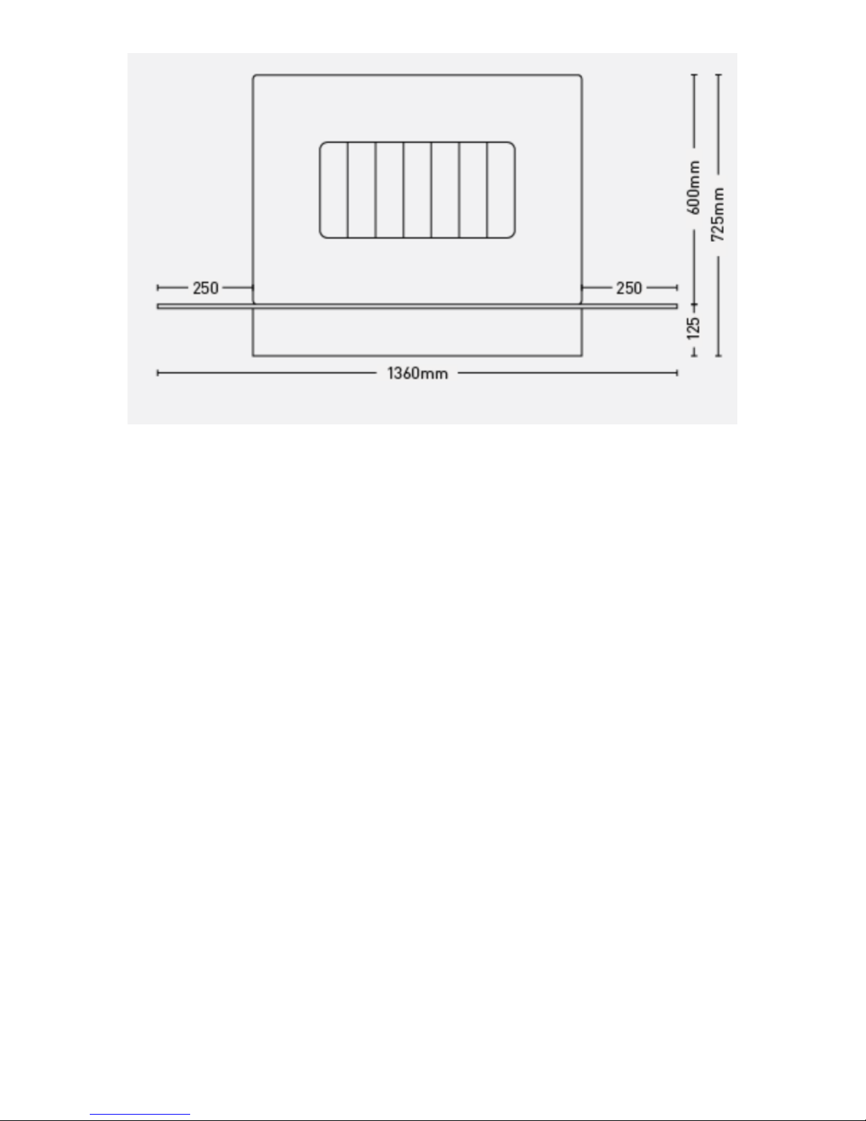
125mm between the bottom of the casing and the floor, see Figure 6.
Page 11

Page 11
41L48L-I01-270318
Figure 4 Wall Mounting Points for 41 Landscape Heater
Figure 5 Wall Mounting Points for 48 Landscape Heater
Page 12
Page 12
41L48L-I01-270318
Figure 6 Dimensions for Fitting the Heater with the Optional Floor Stand
GAS CONNECTION
The gas inlet connection is located on the gas valve underneath the heater at the right
hand side. The gas supply may connect to the heater over the surface of the wall or by
concealed connection below the heater. Concealed pipes should not be routed through
walls without being protected by sleeving or conduit. No more than 2.5m of 8mm
diameter pipe must be used to avoid unnecessary pressure drops.
An isolation tap should be provided on the gas inlet to the heater.
If a concealed gas connection is to be made, the supply pipe should always be sleeved
through walls and floors using the shortest possible route.
When making the gas connection ensure that the front panel will not foul the pipe or
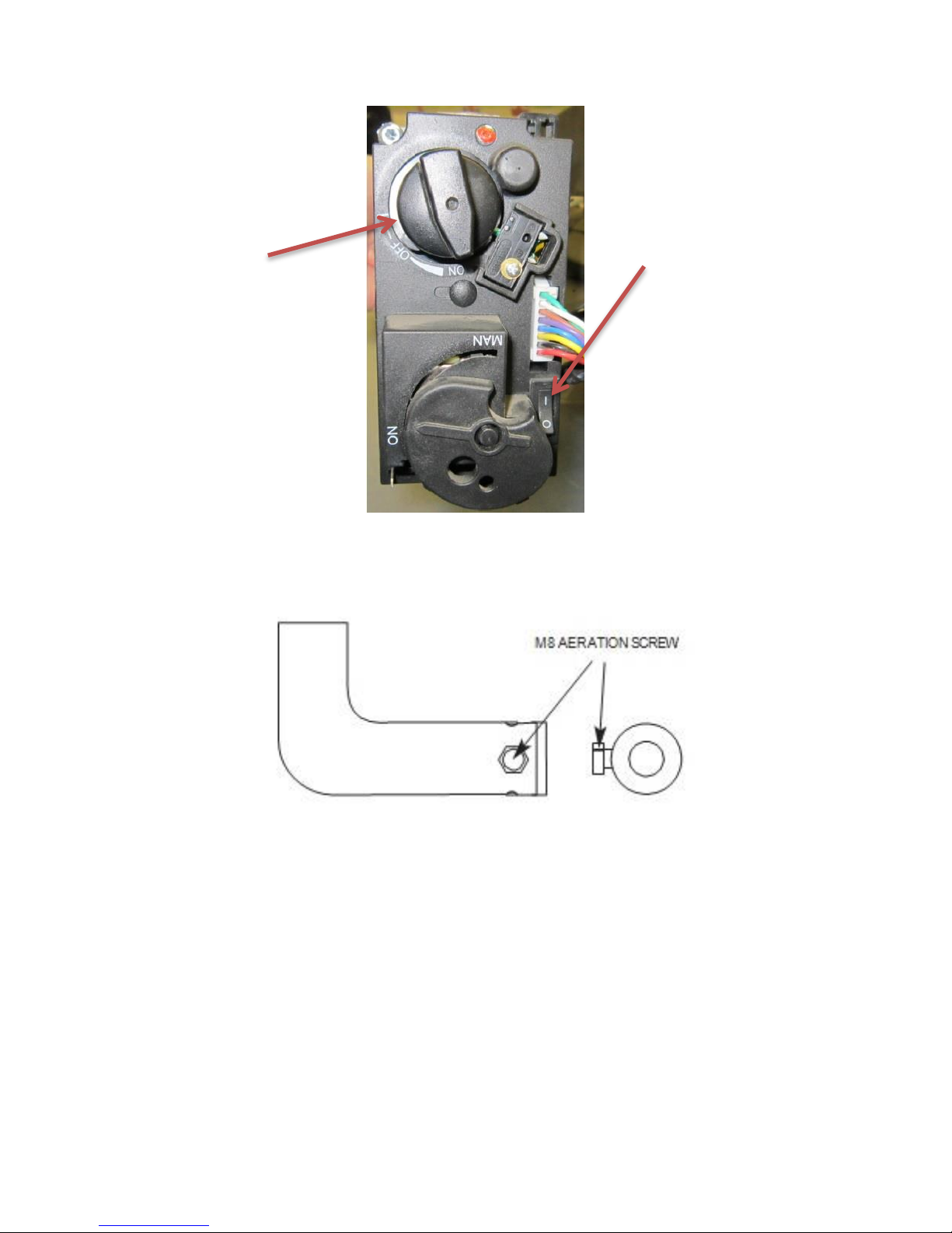
isolation tap. If the heater is to be operated on propane, the M8 aeration screw should be
fitted. If the heater is to be operated on Butane or Butane/Propane mix this aeration screw
MUST NOT BE FITTED see Figure 10.
Page 13
Page 13
41L48L-I01-270318
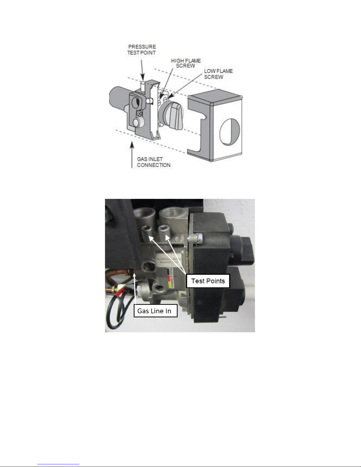
Figure 7 Manual Valve
Figure 8 Remote Valve
Page 14
Page 14
41L48L-I01-270318
Figure 9 Remote Valve Controls
Figure 10 Aeration Screw Location
Ensure rocker switch is turned
to on ( I ) when fitting the
heater body to the wall plate
Combination control
Page 15

Page 15
41L48L-I01-270318
FITTING THE VERMICULITE GRANULES
Pour the vermiculite granules into the burner. Fill the burner completely to the top as
shown in Figure 3.
Do not overfill the vermiculite over the top of the burner in the area of the pilot flame.
Replace the frame and secure using the 2
nuts previous removed.
Under no circumstances should the heater be operated with the glass
frame removed or the glass damaged or without the vermiculite granules.
COMMISSIONING THE HEATER
MANUAL BURNER
The heater is fitted with a pilot light, which is also an oxygen depletion sensor (O.D.S),
piezo spark, and flame sensing device. The control is located behind the front panel on
the right hand side of the heater. The pilot light is located at the right hand end of the
burner.
Should the heater be extinguished for any reason wait 3 minutes before re-ignition is
attempted.
To check the outlet pressure, pull the control valve plastic cover forward and remove it
(Figure 7). Slacken the pressure test point sealing screw and connect a suitable pressure
gauge to the pressure test point (Figure 7).
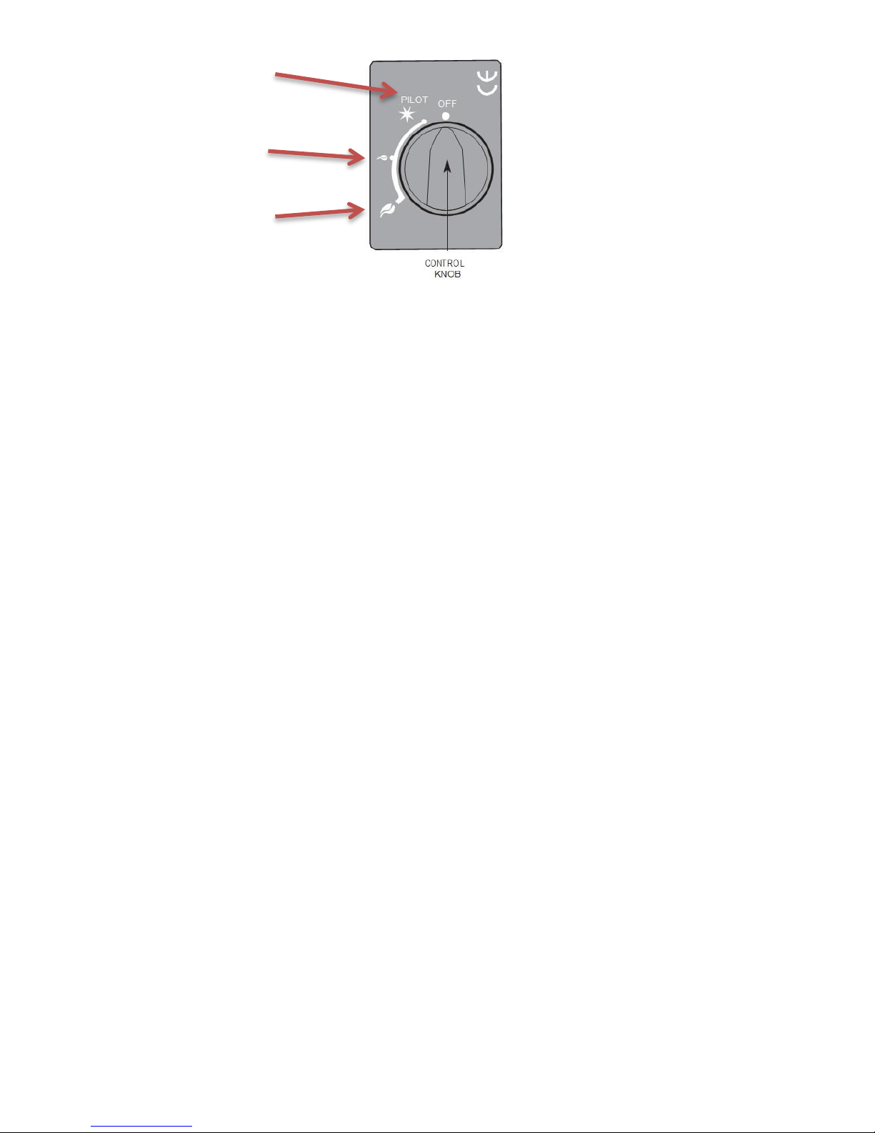
LIGHTING THE PILOT
Depress control knob fully. Whilst depressed turn knob slowly anti-clockwise to ‘PILOT’
setting.
A click will be heard and the spark should light the pilot, repeat until pilot is visibly lit. The
operation of the spark can be viewed on the pilot assembly at the right hand end of the
burner.
Page 16

Page 16
41L48L-I01-270318
Keep knob depressed at this point for 10 - 15 seconds and release the knob slowly.
Preferably the pilot should be left to stabilise for approximately 5 minutes before igniting
the burner.
HIGH SETTING
If the pilot is not already lit, light the pilot as described above.
With control knob at ‘PILOT’ setting, depress and turn anti-clockwise to the ‘HIGH’
setting and release the knob. After a few seconds the burner will light on high setting.
Check that the high burner pressure is in accordance with that given in the TECHNICAL
INFORMATION section. The pressure is factory set and should not require adjustment but
if necessary adjust the HIGH
FLAME SCREW (
Figure 7
).
LOW SETTING
If the heater is not already lit on the ‘HIGH’ setting, ignite the heater and set to the ‘HIGH’
setting as described above. Turn the control knob until the ‘LOW’ setting is reached.
Check that the LOW burner pressure is in accordance with that is given in the
TECHNICAL INFORMATION section. The pressure is factory set and should not require
adjustment but if necessary adjust the LOW FLAME SCREW (Figure 7).
TURNING THE HEATER OFF
From any heat setting, depress the control knob fully and turn clockwise to ‘PILOT’
position.
Disconnect the pressure gauge, tighten the pressure test point sealing
screw and test for gas soundness. Replace the control valve plastic cover.
TURNING THE PILOT OFF
From any heat setting or the ‘PILOT’ position, depress the control knob fully and turn
clockwise to ‘OFF’ position.
Page 17
Page 17
41L48L-I01-270318
Figure 11 Manual Burner Control
REMOTE CONTROL BURNER
The heater is fitted with a pilot light, which is also an oxygen depletion sensor (O.D.S),
piezo spark, and flame sensing device. The control is located behind the front panel on
the right hand side of the heater. The pilot light is located at the right hand end of the
burner.
Should the heater be extinguished for any reason wait 3 minutes before re-ignition is
attempted.
To check pressures, with the outer glass or steel panel removed, slacken the pressure
test points sealing screws and connect a suitable pressure gauge to the pressure test
points (Figure 8).
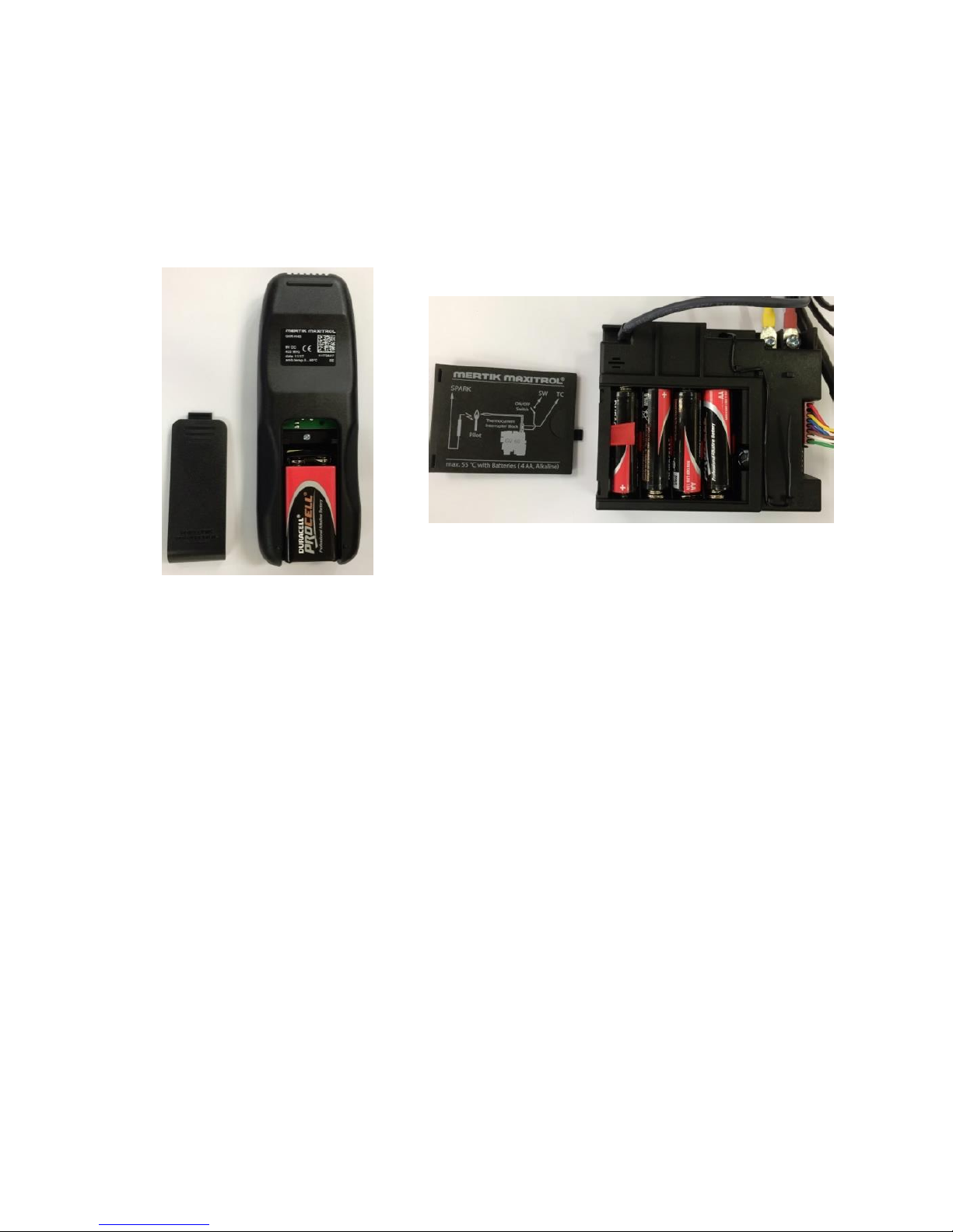
BATTERY FITMENT
Insert the supplied 9V battery in the handset and the four supplied 1.5V AA batteries in
the receiver as shown in Fig 8A & 8B
Ensure the remote valve is set according to Figure 9 before set up.
PILOT
LOW
HIGH
Page 18
Page 18
41L48L-I01-270318
BATTERY FITMENT
Insert the supplied 9V battery in the handset and the four supplied 1.5V AA batteries in
the receiver as shown in Figure 12 & Figure 13.
Figure 12 Handset Battery Fitting
Figure 13 Receiver Battery Fitting
Page 19
Page 19
41L48L-I01-270318
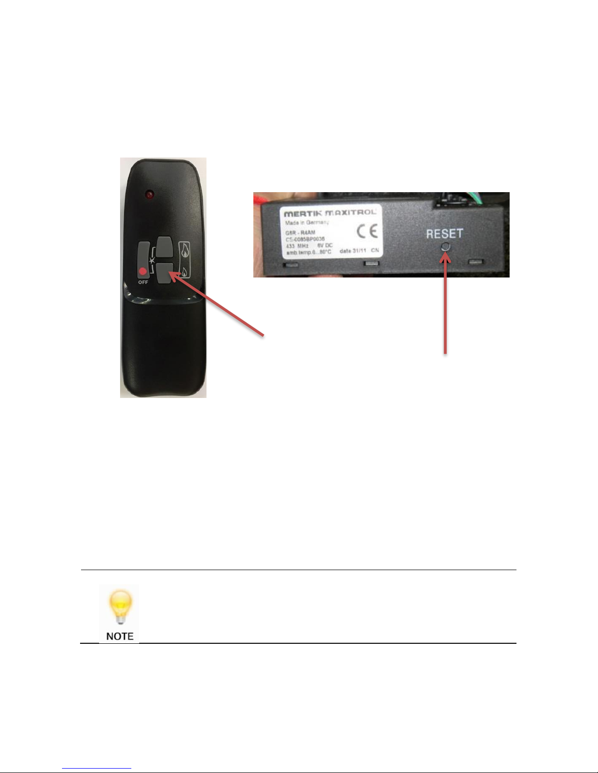
SETTING THE ELECTRONICS CODE
The heater comes with the handset and receiver already paired as part of our in house
quality checks. If the handset does need to be paired, please follow the instructions
below.
Figure 14 Remote Handset
Figure 15 Receiver
A code is selected automatically for all Mertik Maxitrol electronics from among 65000
random codes available. The receiver has to learn the code of the handset.
Press and hold the receivers reset button until you hear two beeps. The first beep is
short and the second beep is long. After the second beep, release the reset button.
Within the subsequent 20 seconds, press the small flame button on the handset until
you hear two additional short beeps confirming the code is set. If you hear one long
beep then this indicates the code learning sequence has failed or the wiring is incorrect.
This is a one-time setting only and is not required after changing the
batteries in the handset or receiver.
Reset button
Small flame button
Page 20
Page 20
41L48L-I01-270318
When lighting the burner with the remote control, if the ON/OFF switch
is not turned on (fig 6C) the unit will issue one long continuous beep.
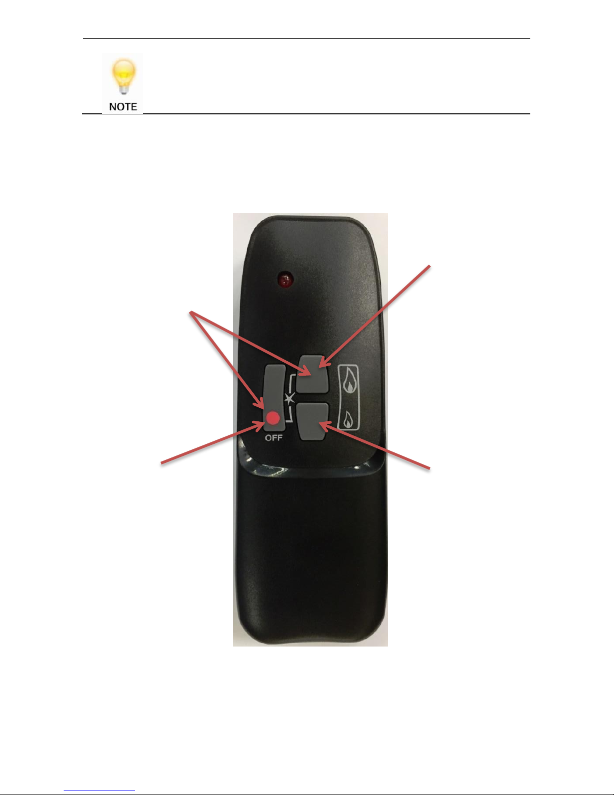
HANDSET OPERATION
Figure 16 Handset Operation
LARGE FLAME BUTTON
Press LARGE FLAME
button to increase the
flame.
SMALL FLAME BUTTON
Press SMALL FLAME
button to decrease the
flame. Hold down the
SMALL FLAME button
to go down to the
PILOT setting
OFF BUTTON
Hold the OFF button to
turn off the heater
Press the LARGE
FLAME button and the
OFF button
simultaneously to light
the heater
Page 21
Page 21
41L48L-I01-270318
FITTING THE OPTIONAL FLOOR STAND & TOP GRILLE
Ensure that the heater has been fitted to the heights shown in Figure 6.
The optional floor stand can now be placed under the heater and centralized.
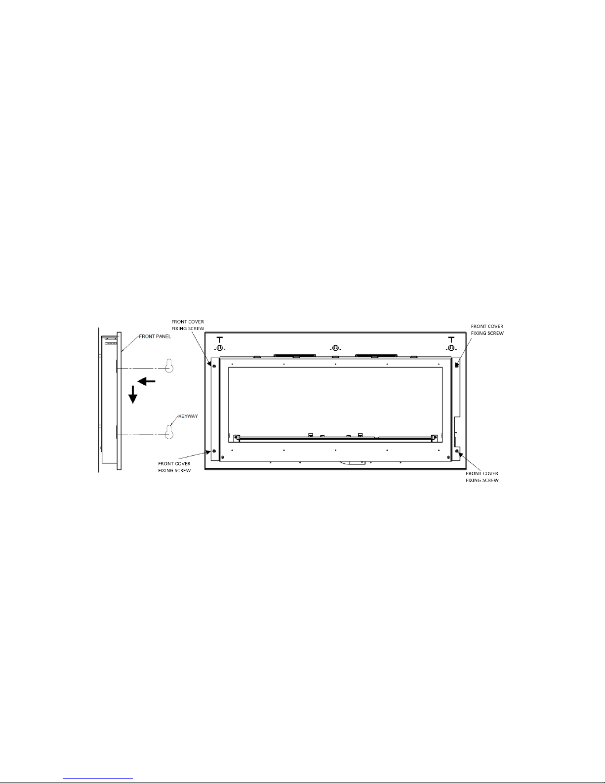
FITTING THE FRONT PANEL
The front panel can now be fitted by aligning the large hole on the keyway holes with
the fixing screws and sliding the front panel down.
The fixing screws can be adjusted to ensure a good fit that will allow the panel to be
fitted & removed but without allowing the panel to be loose and have excessive
movement.
Figure 17 Fitting the Front Panel
To remove the front panel, reverse the fitting procedure.
Page 22

Page 22
41L48L-I01-270318
CUSTOMER BRIEFING
Advise the customer how to use the heater.
Advise the customer that the pilot light should be left on even if the main
burner is switched off.
Point out that the operating procedure is in the User Instructions.
Explain to the customer that the heater has a flame sensing and oxygen
depletion monitoring system.
Point out the explanation of this system in the User Instructions.
Advise that if the monitoring system repeatedly shuts off the heater, it should
be switched off and a specialist consulted.
Advise that if the heater goes out for any reason, wait at least 3 minutes
before re-lighting.
Advise the customer that due to newness of materials the heater may give off
a smell for a period of time after commissioning and that this is quite normal
and any odours should disappear after a few hours operation.
Advise the customer that the heater should not be used if the glass
becomes damaged or without
vermiculite granules.
Stress that no coals or logs must be added to the heater and that any
replacement parts must only be
authorised ESSE spares.
Recommend that the heater is regularly serviced at least once a year by a
qualified person.
Page 23

Page 23
41L48L-I01-270318
COMMISSIONING CHECKLIST
To assist with any potential guarantee claim please complete the following information:-
To be completed by the installer.
Dealer the appliance was purchased from:
Name:
Address:
Telephone No:
ESSENTIAL information:
Date Installed
Model Description:
Serial No:
Installation Engineer:
Company Name:
Address:
Telephone No:
Commissioning Checks – to be completed and signed:
Has the use of the appliance, operation and controls
been explained?
Yes No
Clearance to combustible materials checked?
Yes No Instruction book handed to the customer?
Yes No CO Alarm fitted?
Yes No
Signature:………………………………………………..
Print Name:…………………………………………………
Page 24

Page 24
41L48L-I01-270318
SERVICING INSTRUCTIONS
The heater is fitted with a pilot light and flame-sensing device which is also an oxygen
depletion sensor (O.D.S). This is not adjustable and must not be put out of action. If
any parts of this system requires replacement only original manufacturers parts must
be used.
The following servicing procedure should be carried out regularly and only by a qualified
person.
1. Ensure that the heater is turned off and is cold.
2. Remove the front panel, glass frame securing nuts and the glass frame Fig.2)
3. Carefully remove any deposits of dirt, lint etc., from the vermiculite burner bed,
aeration holes and pilot assembly with a soft brush. Do not use a vacuum cleaner
near the vermiculite burner bed.
4. Clean the pilot aeration ‘hole’.
5. Inspect the catalyst for sign of damage and dirt. The expected life of the catalyst is in
excess of 11,000 hours (10 years of normal use). After this time the catalyst should
be replaced. If there are any deposits of dirt or soot on the catalyst clean with a soft
brush and a vacuum cleaner.
6. Due to high temperatures reached within the heater, surface cracks may appear on
the back board behind the flames. This is quite normal and will not affect the safe
operation of the heater. Replace the glass frame.
7. Check the high and low burner setting pressures as described in COMMISSIONING THE
HEATER.
8. Check the safe operation of the heater:
If a combustion analyser is available check the combustion performance of the heater
as follows:
a. Light the heater on HIGH and after 15 minutes check the combustion
performance is in accordance with Fig.16 above the catalyser.
b. If the Co figures are more than given in Fig.16 this suggests that the
catalyser is due for changing or the aeration holes on the burner
require or new vermiculite granules are required. Turn off the heater
investigate and correct.
9. Check that the purpose provided air vent is non-obstructed.
Table 4 Combustion Performance Limits
Above Catalyzer
Co ppm
Less than 10
Co2%
Approx. 3.0-5.0
Page 25

Page 25
41L48L-I01-270318
USER INSTRUCTIONS
CONTENTS
General Notes
Page 25
Operating The Heater
Page 27
Important Notes
Page 25
Combustion Monitoring
System
Page 31
Clearances
Page 26
Cleaning
Page 31
Ventilation
Page 27
Servicing
Page 32
Burner Arrangement
Page 27
Guarantee
Page 36
GENERAL NOTES
This heater has been individually designed to add charm and character to your home
and provides a highly efficient heat source, coupled with the convenience of clean
burning gas. Due to newness of materials the heater may give off a slight smell for a
period of time after commissioning. This is quite normal and any odours should disperse
after a few hours operation. It is recommended that the heater is used only as a
secondary heat source. An electrical appliance such as a television should not be fitted
above the appliance. It has been supplied for use on Natural Gas or LPG. The data plate is
situated on the Wall Plate (Figure 3)
IMPORTANT NOTES
The installation must be in accordance with National Regulations and must be carried out
by a qualified person. Under no circumstances should the appliance be operated without
the glass frame attached or the glass damaged. All surfaces except the controls are
considered to be working surfaces. Most parts of the heater will get hot during and after
use. If young children, the elderly, or infirm are likely to be near the heater a suitable
fireguard, conforming to BS8423, is recommended. Do not place any objects on top of the
heater. In particular never cover or partially cover the grille. The integral catalyst should be
checked by the installer upon servicing to ensure that there are no defects or obstructions.
The expected life of the catalyst is in excess of 11,000 hours (10 years of normal use).
After this time the catalyst should be replaced. Due to the high temperature reached
within the heater, surface cracks may appear on the backboard behind the flames; this
is quite normal and will not affect the safe operation of the heater. The room that the
heater is installed in must not be used as a bedroom or sleeping area.
Page 26
Page 26
41L48L-I01-270318
Do not use candles or oil lamps. These provide considerable quantities of
pollutant and unhealthy soot particles in your home. Smoke from
cigarette and cigars contain tarry substances, which may also leave
deposits on colder and damp walls when heated.
CLEARANCES
To electrical devices - Under no circumstances must any electrical device (e.g. Plasma
T.V.) be wall mounted above a firewall.
To combustibles - Minimum clearance to the sides of the heater are 100 mm (4in) but
curtains, drapes and other fabrics are not permitted within a distance of 500 mm (20
in) of the stove sides. No such materials are permitted directly above the heater
regardless of distance. Clearance to the front of the heater is 1000 mm (39 in). A
combustible shelf may be fixed to the wall above the heater, providing that it complies
with the dimensions given below and is rated a minimum of 100°C otherwise discolouration
or smells may occur. If in doubt refer to the shelf manufacturer.
The shelf depth may be increased up to a maximum of 457mm (18") but the height must also
be increased accordingly. An increase in height of 25 mm is required for every 12.5 mm of
additional shelf depth. For shelves that are too low, protective devices can be used such
as metal heat deflectors, but it must be assured that the shelf does not reach an
unacceptable temperature before relying on such a solution.
As with all heating appliances, any decorations, soft furnishings, and all coverings (i.e.
flock, blown vinyl and embossed paper) positioned too close to the appliance may
discolour or scorch.
Table 5 Dimensions for Combustible Shelves
Maximum depth of shelf
Minimum distance from top of
outlet grille to underside of shelf
75mm (3 inches)
305mm (12 inches)
150mm (6 inches)
457mm (18 inches)
457mm (18 inches)
1067mm (42 inches)
Page 27

Page 27
41L48L-I01-270318
VENTILATION
Purpose provided ventilation of 100cm2 is required for this heater. This ventilation must
never be blocked or partially blocked. An openable window or equivalent is also
required. Ventilation fitted under, or within immediate vicinity of the heater must not be
used as it may adversely affect performance of the combustion monitoring system (ODS)
system.
The requirements of other appliances operating in the space or room must be taken
into consideration when assessing ventilation requirements. This will have been carried
out by your Gas Safe registered installer.
A supply of fresh air into the room is advisable to maintain temperatures within limits.
The heater MUST NOT be installed in a bedroom, bathroom or any sleeping area.
Additionally for L.P.G. – the heater must not be used in cellars or basements.
BURNER ARRANGEMENT
The burner should only be used with vermiculite granules as shown in the Installation
Instructions. The heater must only be fitted with the vermiculite supplied. DO NOT add
any extra logs or coals.
OPERATING THE HEATER
The heater is fitted with a pilot light which is also an oxygen depletion sensor (ODS),
piezo spark and flame sensing device. The control is located behind the front panel on
the lower right hand side. The pilot light is located at the right hand end of the burner.
Should the heater be extinguished for any reason wait 3 minutes before re-ignition is
attempted. The heater should not be used at a lower setting than the ‘LOW’ position.
Page 28
Page 28
41L48L-I01-270318
MANUAL BURNER
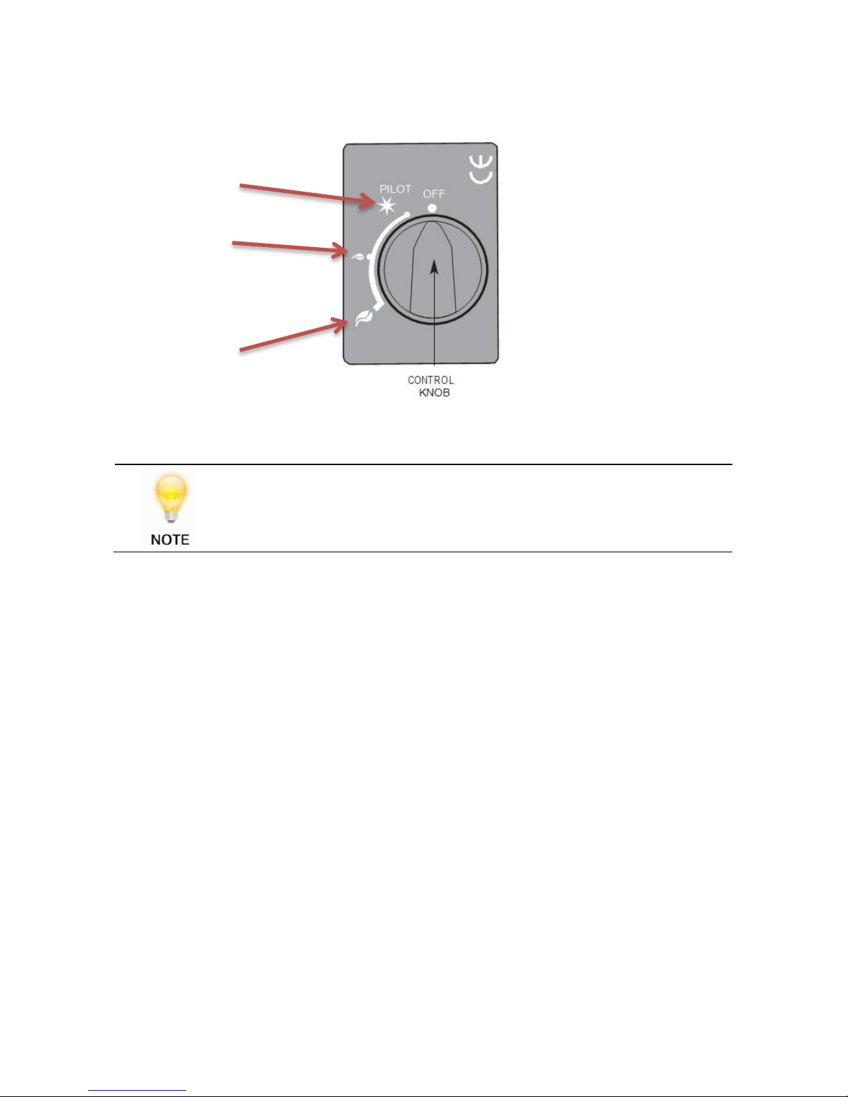
Figure 18 Manual Burner Controls
It is recommended that the pilot light be left ‘on’ even if the main burner
is turned ‘off’.
LIGHTING THE PILOT
Depress control knob fully. Whilst depressed turn knob slowly anti-clockwise to ‘PILOT’
setting.
A click will be heard and the spark should light the pilot. Repeat until pilot is visibly lit. The
operation of the spark can be viewed on the pilot assembly at the right hand end of the
burner.
Keep knob depressed at this point for 10 - 15 seconds and release the knob. Preferably
the pilot should be left to stabilise for approximately 5 minutes before igniting the burner.
HIGH SETTING
Ensure that the pilot is lit as described above.
LOW
HIGH
PILOT
Page 29

Page 29
41L48L-I01-270318
With control knob at ‘PILOT’ setting, depress and turn anti-clockwise to ‘HIGH’ setting and
release the knob. After a few seconds the burner will light on high setting.
LOW SETTING
With the heater lit on ‘HIGH’ setting, as described above, output can be decreased by turning
the control knob progressively in a clockwise direction until the desired level is achieved,
down to the ‘LOW’
setting.
TURNING THE HEATER OFF
From any heat setting, depress the control knob fully and turn clockwise to ‘PILOT’
position.
TURNING THE PILOT OFF
From any heat setting or the ‘PILOT’ position, depress the control knob fully and turn
clockwise to ‘OFF’ position.
Page 30
Page 30
41L48L-I01-270318
REMOTE CONTROL BURNER
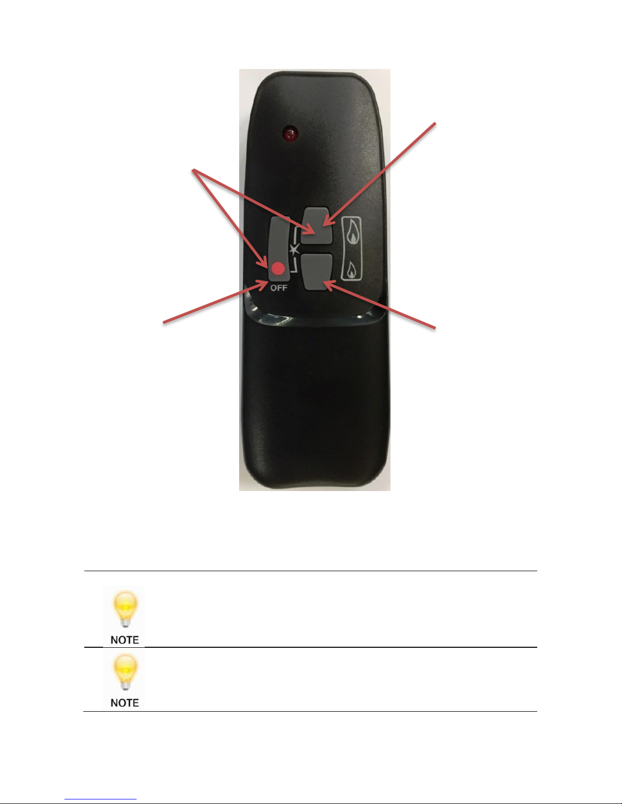
Figure 19 Remote Burner Handset
When lighting the burner with the remote control, if the ON/OFF switch
is not turned on (fig 6C) the unit will issue one long continuous beep.
It is recommended that the pilot light be left ‘on’ even if the main burner
is turned ‘off’.
LARGE FLAME BUTTON
Press LARGE FLAME
button to increase the
flame.
SMALL FLAME BUTTON
Press SMALL FLAME
button to decrease the
flame. Hold down the
SMALL FLAME button
to go down to the
PILOT setting
OFF BUTTON
Hold the OFF button to
turn off the heater
Press the LARGE
FLAME button and the
OFF button
simultaneously to light
the heater
Page 31

Page 31
41L48L-I01-270318
BATTERY REPLACEMENT
When the receiver batteries need changing, frequent bleeps can be heard for three
seconds when the motor turns.
Ensure the appliance is cold, and remove the receiver box from underneath the
appliance and replace the batteries with 4 X 1.5 volts “AA” type quality alkaline
batteries.
If the remote control unit ceases to work. The 9 volt battery should be changed with a
new 9 volt quality alkaline battery. Replacement is recommended every two years.
Mains electrical power is not required as this system runs on batteries
only (Alkaline recommended). Battery information: Handset – 1 x 9V
block, Receiver – 4 x 1.5V AA.
COMBUSTION MONITORING SYSTEM
This heater is fitted with a combustion monitoring safety device (ODS). If the heater shuts
off during use for no apparent reason then several reasons may be suspected. If a door
or window has been opened creating a draught, then pilot disturbance could be the
problem and removal of the draught should resolve this. The heater can then be re-lit in
accordance with the previous section.
If pilot disturbance is not the cause, then the ODS safety system may be in operation.
Switch the heater OFF; call in your installer to check the heater and ventilation.
Remedial work must be carried out as required. DO NOT allow the heater to be used
until the heater and installation is passed as safe. If the pilot continues to be
extinguished, you must call your installer to check the operation of the complete
heater.
CLEANING
Ensure that the heater is turned off before cleaning and is cold. Glass panels can be
cleaned with a suitable glass cleaner. Test on a small area first.
DO NOT use abrasive cleaning agents.
Page 32

Page 32
41L48L-I01-270318
SERVICING
It is essential that the heater is regularly serviced at, least annually.
The heater must only be fitted with the vermiculite supplied. DO NOT use ant extra logs
or coals.
GUARANTEE
CONDITIONS OF GUARANTEE
Your ESSE is guaranteed against defects arising from faulty manufacture for 2 years
when supplied by an ESSE Specialist.
Upon registration of the warranty, ESSE will extend the guarantee period to 5 years from
purchase. Your details must be registered with us by either returning the completed
warranty card or by completing registration on-line at www.esse.com. The warranty
must be registered within 1 month of installation to qualify for the 5 year warranty.
The appliance must be only used for normal domestic purposes and in accordance with
our instructions, be correctly installed and serviced.
The guarantee does not cover:
Installation
Wear and tear
Parts deemed to be replaceable or service parts including electrical components that
may be replaced during the normal usage of the appliance.
This guarantee is personal to the original purchaser and not transferable.
Any stove or defective part replaced shall become the Company’s property
HOW TO PROCEED WITH A COMPLAINT
If you have cause for dissatisfaction with your stove, you should first contact your ESSE
dealer, who will bring your concerns to our attention. We will assess the nature of the
complaint and either send replacement parts for your dealer to fit, or arrange for an
ESSE engineer to inspect the appliance and carry out any work that may be deemed
necessary. If the fault is not actually due to faulty manufacture but some other cause
i.e. misuse, failure to install correctly, or failure to service at regular intervals, a charge
will be made to cover the cost of the visit and any new parts required.
SPARE PARTS
Only genuine ESSE spare parts are recommended.
Page 33

Page 33
41L48L-I01-270318
Page 34

Page 34
41L48L-I01-270318
Page 35

Page 35
41L48L-I01-270318
Page 36

Page 36
41L48L-I01-270318
ESSE Engineering Limited, Ouzledale Foundry, Long Ing, Barnoldswick, Lancashire
BB18 6BJ
Tel. 01282 813 235, Fax: 01282 816 876
Website and On-line Store http://www.esse.com
 Loading...