

Page 1
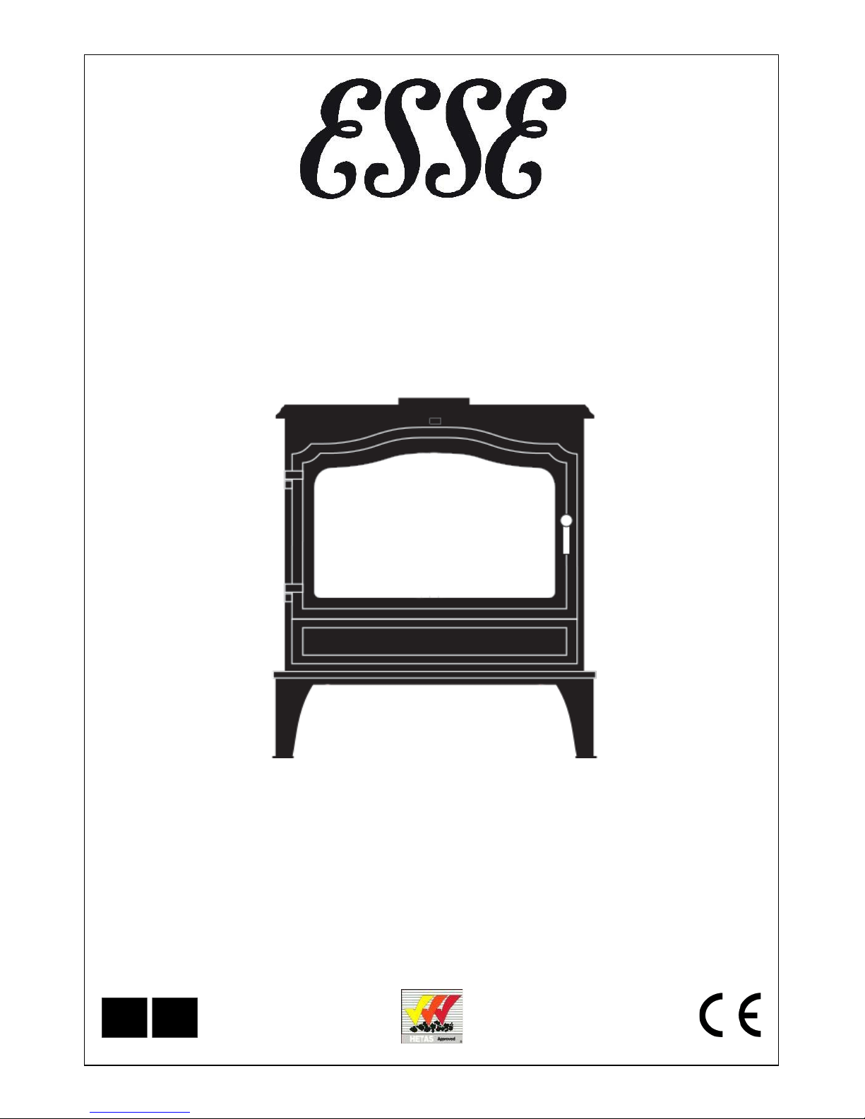
100 MF SE
MULTI-FUEL AND SMOKE EXEMPT STOVES
INSTALLATION & USER INSTRUCTIONS
(TO BE LEFT WITH THE CUSTOMER)
UK & Ireland
GB IE
Page 2
2
CONTENTS
General Safety Notes Page 2
Operating Instructions Page
9
Installa tio n Inst ruc tions
Page 3
Wood Burning
Page 11
Chimney & Flue
Page 3
Solid Mi neral Fuel Burning
Page 1
3
Flue Draught
Page 5
Maintenance
Page 14
Flue Stabiliser
Page 6
Technical Information
Page 1
4
Dimensions & Clearances
Page 6
Guarantee Page 15
• Properly installed, operated and maintained, this appliance will not emit fumes into the dwelling.
However occasional fumes from de-ashing and re-fuelling may occur. Persistent fumes emission
is potentially dangerous and must not be tolerated. If fume emission does persist, open doors
and windows to ventilate the room. Let the fire burn out or eject and safely dispose of fuel
from the applianc e. O nce the fi re is co ld, check the flue a nd chimney for blockages and clean
if required. Do not attempt to relight the fire until the cause of the fume emission has been
identified and corrected. Seek expert ad vice if necessary.
• Do not fit a n extractor fan in the same room as the appliance.
• An adequate air supply for combustion and ventilation is required. As this stove does not
exceed
5.0 kW nominal heat output (Refer to Building Regulations Document J) a purpose
provided air vent is not normally required. However, in certain circumstances a purpose
provided air vent may be necessary – for example, small or tightly sealed rooms. Air openings
provided for this purpose must not be restricted.
• It is important that flue ways are cleaned frequently and the chimney swept regularly. Also
the stove m ust be mai ntai ned in g ood mec hanica l order . The chi mn ey should be swep t at leas t
once per year for smokeless fuel and a minim um of twice per year for other fuels.
• Should it be likely that children, aged or infirm people approach the fire, then a fireguard
should be fitted.
• Avoid the use of aer osol spr ays in the v icinity of the stove when it is in operation.
• This appliance must be installed as per these instructions and regulations complied with.
No modifications or alterations of any kind are permitted.
GENERAL SAFETY NOTES
Page 3
3
INSTALLATION INSTRUCTIONS
The installer has a responsibility under the Health and Safety at Work Act 1974 to provide for the
safety of persons carrying out the installation. Attention is drawn to the fact that fire cement is
caustic and hands must be washed thoroughly after use. The appliance is heavy and care must
be taken during handling. Although the appliance does not contain asbestos products, it is possible
that asbestos may be disturbe d in existing installations and every precaution must be taken. These
instructions give a guide for the installation of the appliance but in no way absolves the installer
from responsibilities to confirm to British Standards, in particular BS8303 and BS6461, relating to
the install ation of solid fuel appliances. All local regulations, including those referring to National
and Europ ean standards need t o be complied with when installing the appliance.
CHIMNEY & FLUE
The successful operation of these appliances relies on the adequate performance of the chimney to
which it is c onnected. The chimney must:
• Have an internal cross section of no less than 320cm
2
(200mm diameter). If wood is the
preferred fuel, the appliance woul d benefit from a six inch liner (150mm) being fitted.
• Be a minimum 4.6m high from hearth lev el to po t.
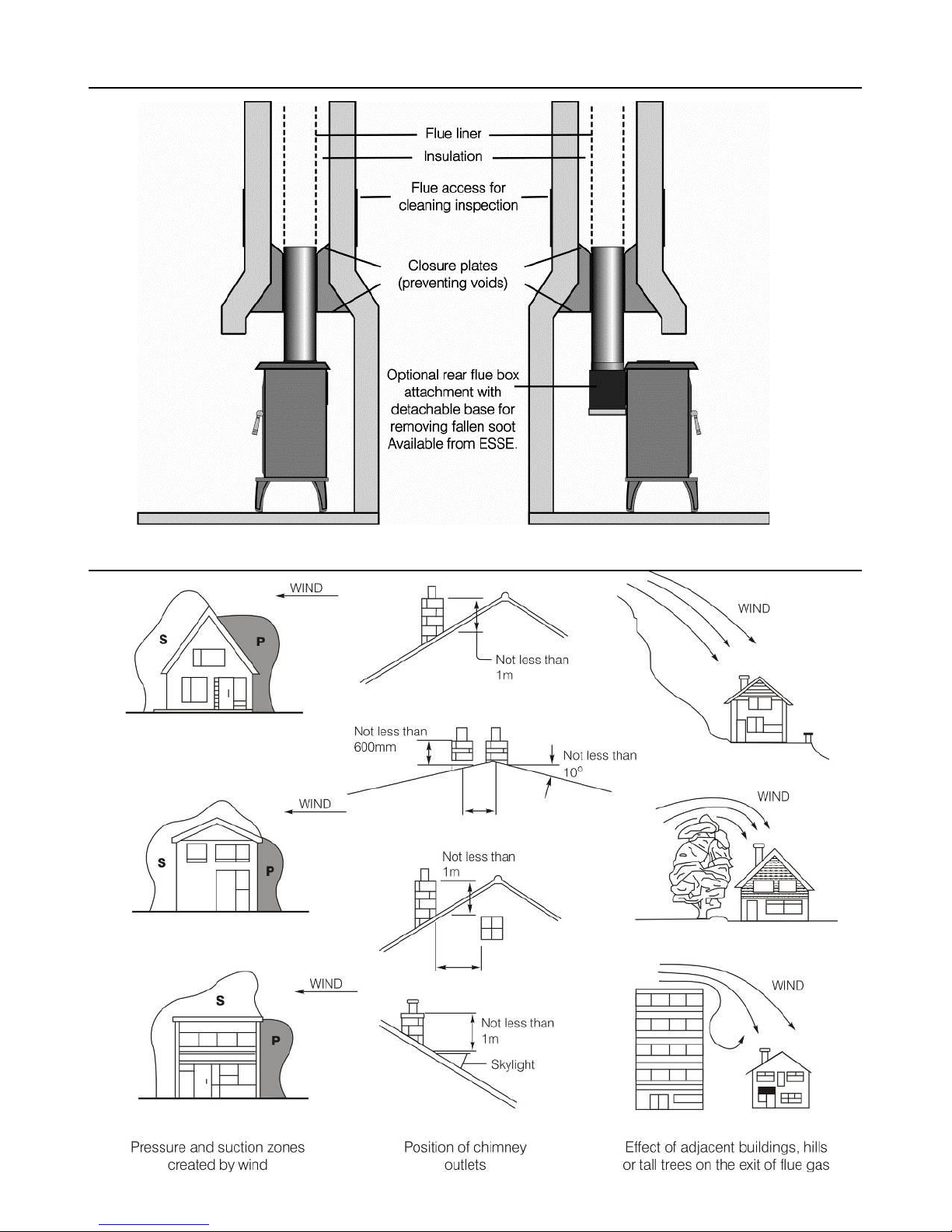
• Be terminated a t least 600mm above roof level so that the chimney does not termin ate in a
pressure zone (see Fig.2).
• Be free from cracks, severe bends, voids and obstructions.
• Be connected to this one applianc e only.
• New chimneys mus t be built in accordance with local building regulations.
• New chimn eys mus t be tested in acc ord a nce wi t h HET AS requirements.
• If this stove is installed as a freestanding appliance, it should not support any part of the
chimney.
• Voids in the chimney should be avoided, as these will prevent a stead y flue draught.
• The stove flue pi pe should pass beyond the narrowing of the chimney (s ee Fig. 1).
• Consideration should be given to falling soot. For rear outlet stoves it may be necessary to
provide a soot catchment area in the flue pipe so that soot does not settle in the path of the
flue gases. The optional rear flue box att achment available from ESSE has a detachable base
that allows for fallen soot to be removed (Se e Fig.1).
• A flue/chimney access point may also be required so that the state of the chimney can be checked
and any fallen soo t removed.
• External flues must be insulated to prevent heat loss.
• Parts of the appliance, especially the external surfaces,
will be hot to touch when in operation and due care will
need to be taken.
• Your stove should not be used as an incinerator and only
recommended fuels shall be used.
Page 4
4
F
ig. 1 – Ideal Flue Connections.
Fig.2 – Chimney and Flue Performance
Page 5
5
FLUE DRAUGHT
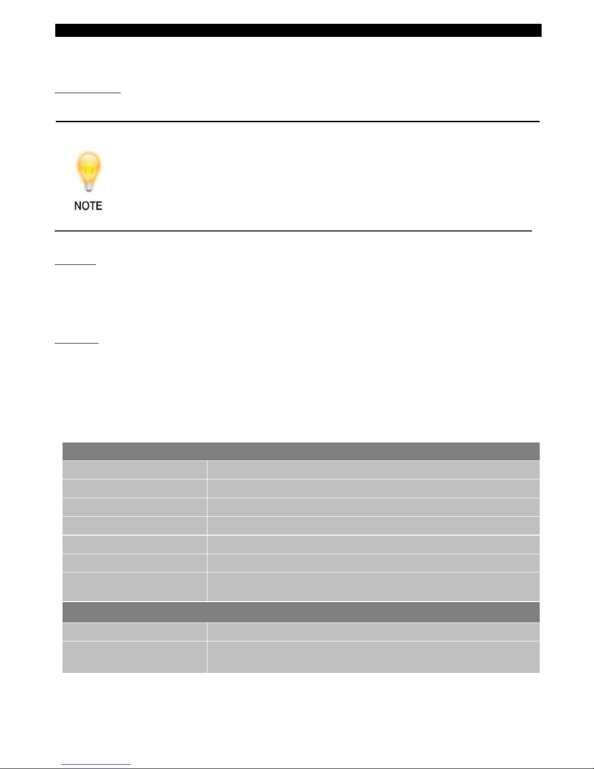
The chimney can be checked, before the stove i s instal led, with a smoke pellet. If th e chimney doesn’t
pull the smoke it may suggest the chimney needs attention (see the Flue Diagnosis Table, below).
Measurements
There is a flue draught tes ting poi nt on the ri ght hand upper side of the stove. (See fig. 3)
This test is only a guide as an apparently poor flue may improve once the stove is
installed, lit and the flue is warmed. If, once the stove is installed, there is any doubt
that the chimney is providing an adequate draught, a flue draught reading can be taken
with the stove lit. Two flue draught readings should be taken, one with the stove at
minimum firing rate and one at maximum firing rate. Close all doors & windows during
the test.
Minimum
The stove should be lit and allowed to warm the flue thoroughly. The air controls can then be set so that
the stove burns on a low setting. Allow the burning rate to become steady. The flue draught reading
should now be taken with the primary air intake closed and the airwash control fully open.
Maximum
The primary air intake can now be opened to allow the stove to burn at maximum rate. Give the stove
some time for the burning rate to become steady and then close the primary air intake, make sure the
airwash control is fully open and take a flue draught reading immediately.
Ideally, the flue draught reading should range between 0.05’ W.G (12.45 Pa) and 0.1’ W.G (24.9
Pa). Any readings significantly outside this range may indicate the need for remedial action.
Low flue draught symptoms: difficult to light and smoke coming into the room.
CAUSE REMEDY
Cold chimney Line the chimney
Chimney too short Extend the chimney
Down draught Relocate/extend chimney terminal. Fit an anti down draught cowl
Chimney diameter too large Line the chimney
Chimney obstruction Clear/sweep the chimney
Restricted air supply
Check for competing draughts (other chimneys, extractor hoods/fans).
Fit an air vent if the room Is sealed.
High flue draught symptoms: fire difficult to control, fuel will not last, stove too hot, stove damage, chimney
fire.
CAUSE
REMEDY
External wind conditions
combined with chimney terminal
Fit stabiliser cowl.
Fit flue dr aught stabiliser.
Page 6
6
FLUE STABILISER
A flue stabiliser can be fitted to reduce the draught through the stove if the flue draught is too high. The
flue stabiliser should be:
• Fitted in the same room as the stove
• The same size as the flue pipe
• Note if a stabiliser is fitted, ventilation will need to be increased.
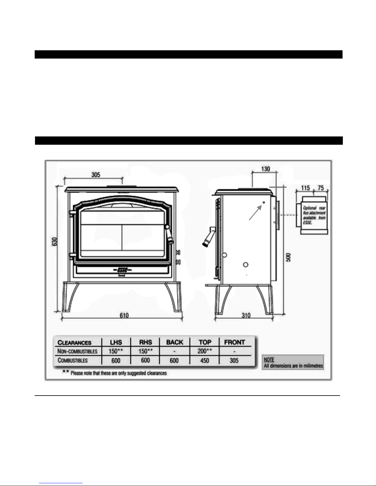
DIMENSIONS & CLEARANCES
Fig. 3 Stove Dimensions
Log Stores
The height of the fitted legs on a 100 are 150mm. The log stores available are 220mm and 300mm in height.
Adding an additional 70mm or 150mm in height when fitted. Clearances remain the same. To retrofit the
log store, remove stove innards, unscrew the legs from the base of the existing stove, lift the stove body
on top of the log store and screw into place. Then put the innards back inside vice versa to how you
removed them.
Flue Test Point
Page 7
7
Position
The overall dimensions of the stove are shown in Fig. 3. The table above indicates recommended distances
between the stove and surrounding combustible materials. As a rule, any surrounding combustible
material should not exceed 80 ºC. There should be sufficient space around the stove for service work.
Hearth
The construction of the hearth must conform to Building Regulations, must be firm, non-combustible and
capable of supporting the stove. (Refer to Building Regulations Document J). The stove has been
independently certified as suitable to stand on a 12mm (½'') thick non-combustible hearth.
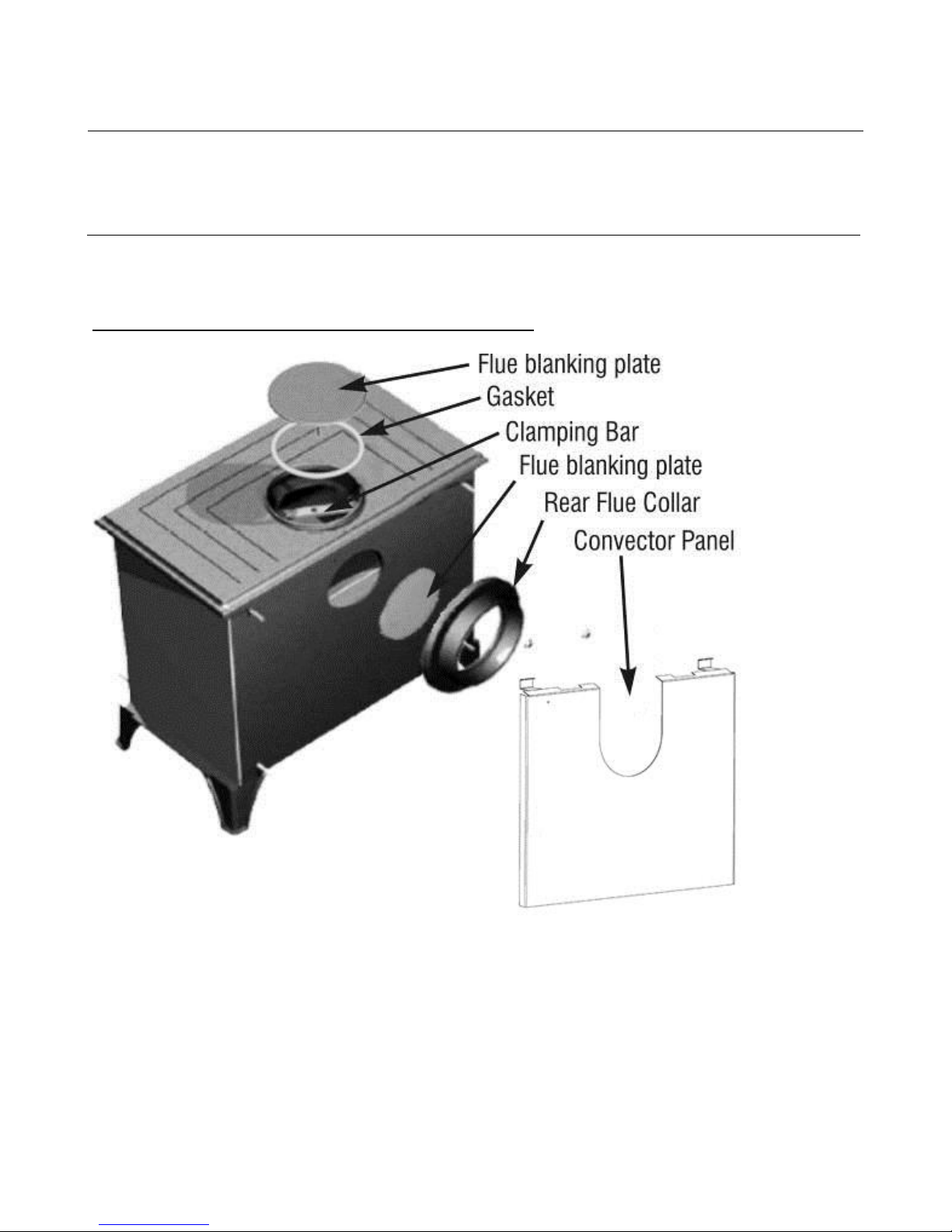
F
ig. 4 – Arranging the flue plug for top or rear outlet
Page 8
8
Fig. 5 – Using the Stove Mitt
The flue pi pe us ed to co nnec t the sto ve to t he chim ney i s 5'' (1 25mm ) in diam eter . The s tove is supplied
ready for top flue connection. For a rear flue conne ction, an optional ESSE rear flue box or
an ESSE cast iron flue collar are available. The rear flue box attachment allows the stove
to be installed further out of any building recess. Fig.1 shows suitable flue connections.
Part Numbers: Blanking Plate (ES -038), Flue Collar (ES-039)
Flue Connection
Page 9
9
1. The installa tion must allow for adequate chimney sweeping.
2. Avoid using bends grea ter than 45 ºC to the vertical. All flue pipe sections should be as close to
vertical as possible.
3. All joints in the flue sys te m mus t b e effectively sealed.
4. All flue sockets must face upwards.
5. Check the appliance for soundness of seals between castings and main components and that all
supplied parts and fitting a re corr ectly fitted.
On completing the installation, check that all the internal components of the stove are positioned
correctly.
Check – ash pan, iron grat e, baffle, si de and back bricks.
OPERATING INSTRUCTIONS
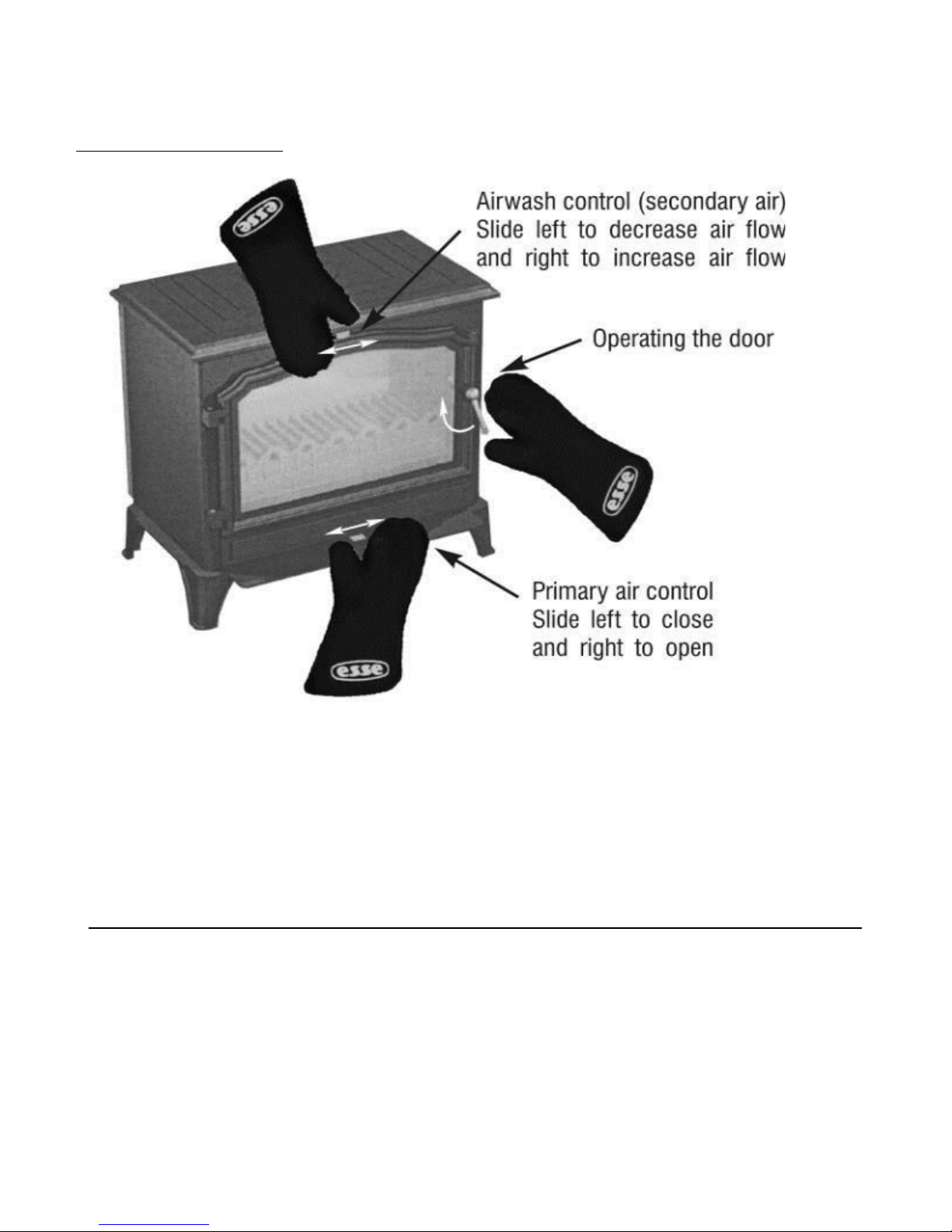
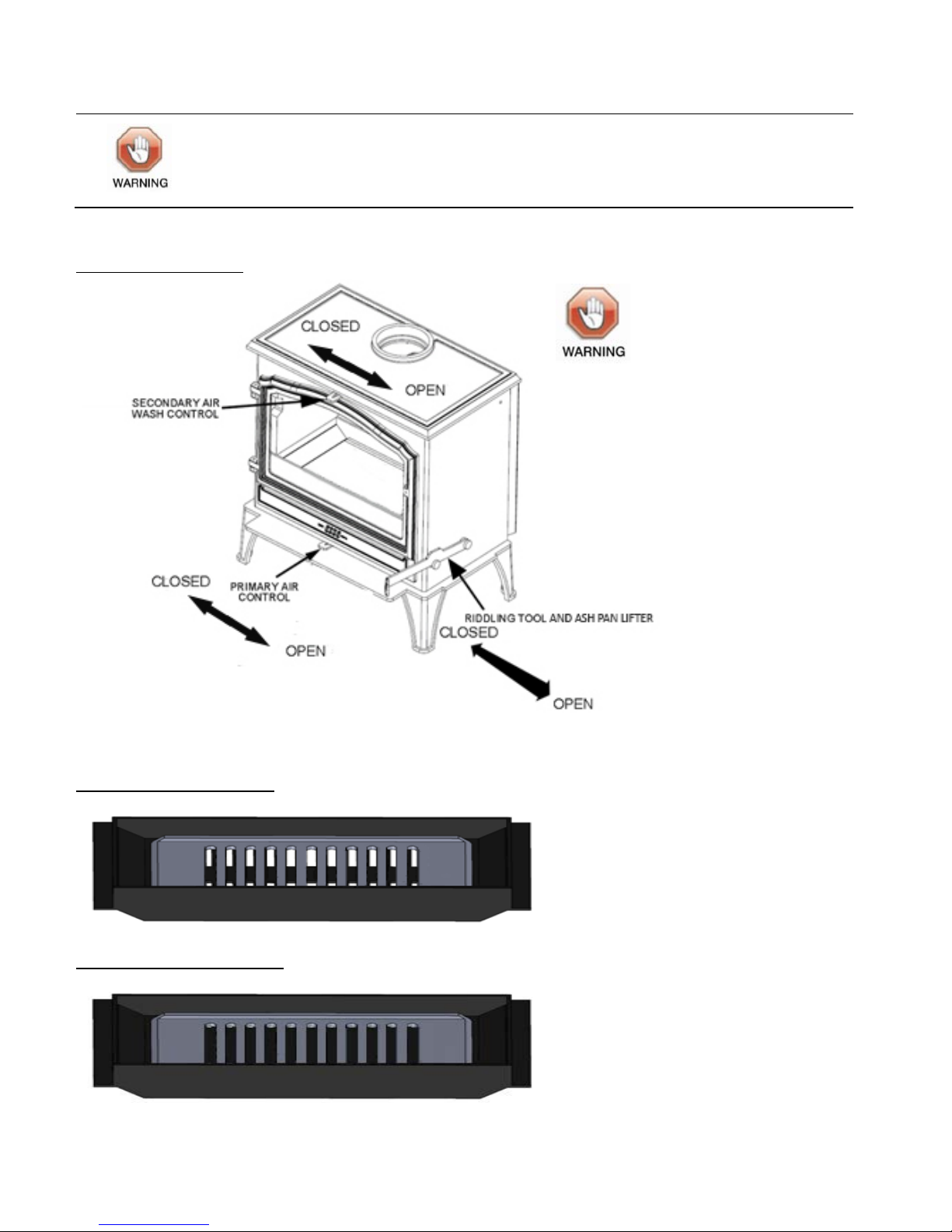
Fig. 5 shows stove and its controls.
Additional loose parts supplied inside your stove include:
• A stove mitt – fo r removing the ash pan, adjusting the p rimary air controls, adjusting the air
wash control, and op erating the door handle. Fig.5 shows how the stov e mitt is used.
• A Riddling Tool - For operating the riddling grate and lifti ng the ash p an in and out.
Smoke Exempt stoves need to maintain an open air supply unlike a
standard Multi-Fuel stove. As such the stove will not shut down like a
standard Multi-Fuel Stove and is designed to continue to draw air so that
is can meet local authority clean air act regulations.
Over firing will damage you stove.
To maintain peak efficiency, your stove should burn approximately 1.7kg of
well-seasoned wood per hour.
Your stove should not be used as an incinerator and only recommended fuels shall
be used.
Im
portant Installation Notes
Your Stove
Page 10
10
Parts of the appliance, especially the external surfaces, will be hot to touch when
in operation and due care will need to be taken
Fig. 6 – Stove Controls
Fig. 7-Riddling Grate Open
Fig. 8-Riddling Grate Closed
Always use stove mitts
when adjusting
controls and opening
or closing the door.
Page 11

11
WOOD BURNING
Lighting and Controlling the Stove
Before lightning the fire for the first time ensure that the baffle, ash pan, side and back bricks and all the
internal components are in position. Burning without either will result in the stove overheating
and being damaged. For w ood bur ning, set the riddling grate to closed (s ee Fig. 8).
Open the air wash control and the primary air control fully. Place some tightly rolled paper on top of
some crumpled paper on the base towards the back of the stove. On top of this, place some small pieces
of wood. Light the crumpled paper and close the door. Once the fire becomes established add some
larger pieces of wood. As the stove comes up to temperature close the primary air control using the stove
mitt as shown in Fig.5. The burning rate of the stove can now be regulated by the rate at which fuel is
added and by adjusting the air wash control.
With the above in mind it is plain to see that the stove should ideally be run with the primary air inlet
closed and the air wash control open whenever possible. Another advantage of running the stove with
the air wash open is that the air is being drawn into the stove travels across the glass forming an air
barrier between the glass and the fire bed helping to prevent smoke particle sticking to the glass.
If the fire dies down too low, opening the primary air control for a short period will revive it. When
reviving a low fire it is important to also use kindling before adding larger logs to help prevent smoke.
Wood burns efficiently when the air for combustion is supplied from above the fire bed
rather than below. The air suppli ed above the fire bed provides the oxygen necessary
for the volatile gases (smoke), given off by the wood as it heats to combust. This
ensures that the gases are burnt and used to heat the stove instead of being wasted up
the chimney or condensating and forming tarry deposits inside the stove, in the flue or
on the stove glass. Running the stove with the primary air control open and the air wash
control closed will provide oxygen for the wood to burn on the fire bed but will not
provide air for the volatile gases above the fire bed to combust resulting in a smokey
inefficient fire.
Ash Removal
Only remove small amounts of ash from the firebox. When de-ashing, leave 30-40mm depth of ash in the
bottom of the firebox for the best performance. Always use the stove mitt to open and close the door.
Correct Running Temperature for Burning
To get the best results from your stove it is recommended that a wood stove thermometer (available
from your stove dealer) be fitted to the flue pipe above the stove, at eye level if possible. The figures
below show the recommended temperature of the flue gases:
115ºC – 245ºC (240ºF - 475ºF)
The flue gases should be in this temperature band for the safest, most efficient and most economical
operation of your stove.
Page 12
12
Below 115ºC
This is below the condensation point of wood gases and may cause the buildup of tar in the chimney,
dirty the stove gla ss and result in the ineffi cient bur n ing of fuel.
Above 245ºC
Too hot. Heat will be wasted up the chimney. Excess heat may damage the stove or ignite any existing
accumulation of tar resulting in a chimney fire.
Extended Burning
Loading a large amount of wood into the stove all at once wi l l reduce the temperature insi de the stove.
If the temp erature is too low, the gases gi ven off from the wood will be too low to c ombust resulting in
a lot of smoke covering the inside of the stove, including the glass, with soot. To combat this problem it
is a good idea to increase the t emperature of the stove before load ing by further opening the air inlets.
Load the wood and leave the air controls open until the moisture is driven out of the wood and the stove
is back up to an efficient operating temperature. The air inlets can then be reduced to the hold the
temperature of the stove. Loading the stove little and often will help keep the stove temperature steady.
When loading wood, make sure that the end grain of the wood in the stove is pointing away from the
glass, otherwise the mo isture and gases coming from the end grain of the wood will dirty the glass.
Types of Wood for Fuel
For best results use well-seasoned hardwoods such as Oak, Ash, or Beech. Allow wood to dry out under
cover in well-ventilated conditions for at least twelve months. As a rough guide wood is ready for burning
when radial cracks appear in the end of the logs. Properly dry wood means it should have a moisture
content of less than 20% which can only be accurately measured using a moisture meter. Burning wood
that is not seasoned will result in tar being deposited in the stove, on the glass and in the flue ways. This
buildup of tar is a hazard and if it ignites m ay cause a chimney fire. Re sinous softwood burns well and
gives a high output for short periods but is not as efficient and does not last as long as hardwood.
The above text sho uld be us ed as a guide only. The ideal operation of your stove
depends on a number of factors, which vary w ith each installation, and so
gaining experience opera ting your stove is the only way to lea rn its best o peration.
Peat
Peat is a fuel conveniently available in some areas and should be burned in the same manner as wood.
Page 13

13
SOLID MINERAL FUEL BURNING
Set the riddling grate to open (See Fig. 7).
Before lighting the fire for the first time ensure that the baffle, and the side and back bricks are in
position. Burning without either will result in the stove castings overheating and being damaged.
Open the air wash control and the primary air control fully. Place some tightly rolled paper on top of
some crumpled paper on the base towards the back of the stove. On top of this, place some small pieces
of wood and on top of that a few small pieces of mineral fuel. Light the crumpled paper and close the
door. Once the fire becomes established and the fuel is burning, more fuel can be added. When the stove
is hot and the fuel is no lon ger produci ng smoke, the air wash control can be reduced. The burning rate
of the fire can now be controlled with bottom air slider. As air from the spinner flows up through the
grate it will cool the grate bars preventing them from overheating and becoming damaged. Reducing the
air inlet and introducing air only from the air wash will allow the fuel to burn but the grate will not be
cooled resulting in damage to the grate bars. When controlling the fire, the air inlet should be altered
gradually. Reducing the primary air dramatically and all at once on a hot stove will cause the fuel to
clinker and will result in a buildup of gases and smoke which could ignite with a bang the moment air is
reintroduced.
Before adding a large amount of fuel, the grate should be de-ashed and the ash pan empt ied. Add the
fuel sloping it from the front coal bar up to the back of the stove to the level of the top of the back brick.
Open the primary air inlet and let the fire burn for a period on high rate in order to hit the stove back up
to temperature and drive off the moisture and gases in the fuel. If a lot of smoke is produced on reloading,
the air was h control can be opened furth er to keep the smoke back from the glass. As the fire gets back
up to the te m perature, reduce the air wash c ontrol and reduce the primary air inlet to suit the burning
rate. The exact setting of the air controls depends on a number of variables includ ing: the flue draught,
the fuel used and the installation and so the best setting for your stove can only be learned by experience.
Ash Removal
The level of ash should not be allowed to build up to the level of the grate. If the level of ash becomes
too high the air through the grate will become restricted causing the grate bars to overheat and
preventing the fuel from burning efficiently. Shake the riddling grate to de-ash the grate. Th e ash will
fall through the slots i nto the ash pan. Empty the ash pan regularly.
Mineral Fuels
Ordinary bituminous house coal is not recommended and must not be burned in smoke control areas.
Burning bituminous house coal will result in a sooty stove and chimney, and the stove glass will require
cleaning r egularly. There are numerous natural ant hracites and manufactured smokeless fuels that will
burn cleanly and have more reliable burning characteristics. A list of these fuels and their suitability is
produced by HETAS (www.hetas.co.uk). Consult your local fuel merchant to find out what is available in
your area. Petro-coke should not be used as it burns very hot and will damage the stove.
Lighting and Controlling the Fire
Extended Burning
Page 14

14
MAINTENANCE
The stove should only be cleaned when it is cold. The exterior can be dusted with a firm brush. Do not
use a cloth, as this will drag on the paint finish leav ing lint on the surface. Fro m time to ti me it may be
necessary to renovate the exterior by repainting. High temperature stove paints in aerosol form are
available from your stove dealer. Do not use this form of paint until the stove is cold and always read the
instructions on t he container befor e starting to paint. The door glass is made of a special heat resisting
ceramic and may be cleaned when cold with proprietary glass cleaning liquids and a dry cloth.
The following procedure should be followed if the stove is not to be used for a long period, summertime
for instance. Remove all the ashes from the grate and ash pan and use a vacuum cleaner nozzle to clean
ash from the base of the stove. Remove the baffle plate and brush the flue ways. Close the door and
open the air inlets fully. This action will allow air circulation through the flue ways and help to avoid
corrosion and condensation.
Servicing / Chimney Sw eeping
Regular maintenance should be carried o ut by a competent engineer / chimn ey sweep at least a nnually
& perhaps bi-annually.
TECHNICAL INFORMATION
Normal heat output – wood 5.0 kW
Nominal heat output – solid mineral fuel 4.5kW
Weight of stove 83.6 kg
Minimum chimney draught 12 Pa (0.05 W.G)
Mean flue gas temperature – wood 244 ºC
Mean flue gas temperature – solid mineral fuel 235 ºC
Flue gas ma ss flow - wood 3.1 g/s
Flue gas ma ss flow – solid mineral fuel 3.6 g/s
This appliance is not suitable for installation in a shared flue system.
Cl
eaning the Stove
Shutting Down the Stove (Long Term)
Page 15

15
GUARANTEE
Your ESSE stove is guaranteed against defects arising from faulty manufacture for five year subject to
the following express conditions. Failure to comply with these conditions will invalidate the guarantee.
• Your ESSE dealer or a suitably qualified engineer must install the stove. Upon installation the
receipt must be kept as proof of purchase.
• The guarantee is five years from date of purchase.
• The guarantee does not cover parts deemed to be replaceable in the normal usage of the
stove. Thes e par ts are li st ed below:
Glass panels, rope seals, glass seals, bottom grate, ash pan, firebricks, baffle plate.
If you have cause for dissatisfaction with your stove, you should first contact your ESSE dealer, who will
bring your concerns to our attention, We will assess the nature of the complaint and either send
replacements parts for your dealer to f it, or nominate a regional engineer to inspect the appliance and
carry out any remedial work that may be necessary. If the fault is not actually due to faulty manufacture
but some other cause i.e. misuse, failure to install correctly, or failure to service at regular interva l s, a
charge will be made to cover the cost of the visit and any new parts required. In the 1
st
year ESSE will
only deal w ith the dealer direct.
Only genuine ESSE spare parts are recommended, parts that may need occasional replacement are:
Glass
Fire bricks
Ash pan
Fire grate
Rope seals
Operatin g too l
Door handle
Mitt
Baffle
Conditions of Guarantee
How to Proceed With a Complaint
Spare Parts
Page 16

16
10/15
ESSE Engineering Limited, Ouzledale Foundry, Long Ing, Barnoldswick, Lancashire, BB18 6BJ
Tel:
01282 813 235, Fax: 01282 816 876, e-mail: [email protected]
Website: http://www.esse.com, On-line store: http://www.esse.com
/spareparts
 Loading...