

Page 1
Manual – epc610 Camera Module V1.0
Time-of-flight camera epc610, 8x8 pixel
General Description
The epc610 Camera Module V1.0 is a fully assembled and tested
3D TOF camera for the evaluation of the epc610 Time of Flight
(TOF) product.
The module includes an epc610 TOF Imager chip, an active IR
LED illumination for the observation area, a complete lens system
and has a cable interface to the mainboard, allowing a flexible and
convenient placement in a lab setup. The module has a 8.7° x 8.7°
optical aperture angle.
In combination with the epc600/610 Evaluation Kit, which provides
all hardware to operate the epc610 Camera Module V1.0, the user
has a fully functional TOF imager evaluation system.
The included comprehensive application software enables the user
to explore the 3D TOF technology as well the epc610 imager chip.
Features
■ Fully functional TOF camera with 8x8 pixel epc610 Imager chip.
■ Comprehensive application software with graphical user interface
to operate the epc610 chip inside the camera.
■ Automatic mode with adaptive integration times.
■ Manual mode to run the camera in individual set-up or to analyze
raw data.
■ Possibility to store and reload operating configurations.
■ Functionality for logging measurement data on PC.
Purpose
■ Performance demonstration of the epc610 chip in terms of
speed, operating range and accuracy.
■ Demonstration and evaluation hard- and software.
■ Development system for user's own epc610 chip application.
Overview
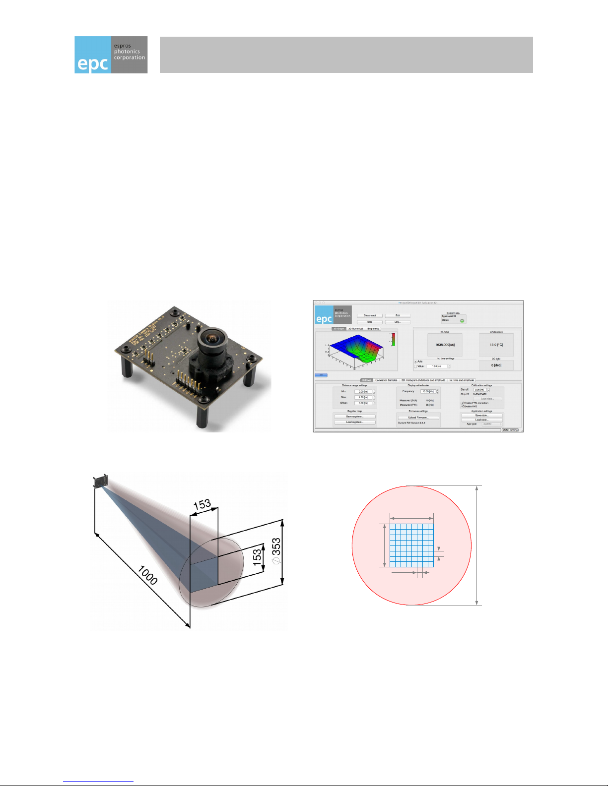
Figure 1: The epc610 Camera Module V1.0 Figure 2: The main dialog of the graphical user interface
with 3D data representation
153mm
153mm
19.1mm
19.1mm
353mm
Figure 3: Field of view of the camera Figure 4: Illumination spot size
and pixel field in the object area
Receiver spot: 153 x 153 mm (8.7° x 8.7°)
Emitter spot: 353mm diameter ≙ □ 250 x 250mm
© 2014 ESPROS Photonics Corporation
Characteristics subject to change without notice
1 / 26 Manual epc610_Camera - V1.5
www.espros.ch
Page 2
IMPORTANT INFORMATION
SAFETY ADVICE
DO NOT LOOK DIRECTLY INTO THE CAMERA UNDER OPERATION !
Depending on the mode of operation, the camera device emits highly concentrated non-visible infrared light. It can be hazardous to the
human eye. The use of these devices has to follow the safety precautions given in IEC 60825-1 and IEC62471.
THIS EVALUATION KIT SHOULD ONLY BE INSTALLED AND USED BY AUTHORIZED AND FULLY TRAINED PEOPLE. ALL INSTRUCTIONS IN THIS MANUAL AND IN THE RELATED DOCUMENTS HAVE TO BE FOLLOWED AND FULLY COMPLIED WITH. IN
ADDITION, THE INSTALLER AND USER IS REQUIRED TO COMPLY WITH ALL LOCAL LAWS AND REGULATIONS. SHOULD ANY
OF THESE INSTRUCTIONS NOT BE CAREFULLY FOLLOWED, SERIOUSLY INJURY MAY OCCUR. THE INSTALLER AND USER IS
FULLY RESPONSIBLE FOR THE SAFE USE AND OPERATION OF THE SYSTEM. IT IS THE SOLE RESPONSIBILITY OF THE IN STALLER AND THE USER TO ENSURE THAT THIS PRODUCT IS USED ACCORDING TO ALL APPLICABLE CODES AND STANDARDS IN ORDER TO ENSURE SAFE OPERATION OF THE WHOLE APPLICATION.
ANY ALTERATION TO THE DEVICES BY THE BUYER, INSTALLER OR USER MAY RESULT IN UNSAFE OPERATING CONDITIONS.
ESPROS photonics AG IS NOT RESPONSIBLE FOR ANY LIABILITY OR WARRANTY CLAIM WHICH RESULTS FROM SUCH MANIP ULATION.
THIS DEVICES MAY NOT BE USED FOR APPLICATIONS OTHER THAN THE EVALUATION OF THE DESIGNATED DEVICES.
THIS DEVICES MAY NOT BE USED IN SAFETY APPLICATIONS, EXPLOSIVE ATMOSPHERES, OR IN A RADIOACTIVE ENVIRONMENT.
IMPORTANT INFORMATION
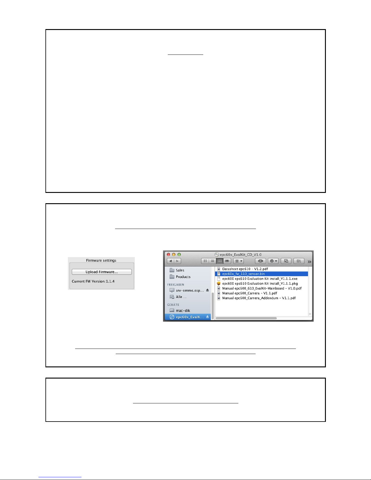
THIS CAMERA COMES WITH ITS OWN CALIBRATED FIRMWARE.
For proper operation of the Evaluation Kit upload the correct firmware from the CD ROM to the evaluation board.
Do this each time, when you are changing the camera module.
User interface:
Use the dialog “Firmware settings” Upload the binary file “epc60x_fw_xxx_sensor”
ALSO, MAKE SURE THAT YOU ALWAYS USE THE LATEST SOFTWARE VERSION ON YOUR MAC / PC.
USE THE APPROPRIATE INSTALLER THAT IS ALSO ON THE CD.
IMPORTANT INFORMATION
THIS CAMERA COMES WITH FOCUSED OPTICS.
Do not touch the lens. Do not twist or turn the lens. Otherwise a degradation of the measurement occurs.
© 2014 ESPROS Photonics Corporation
Characteristics subject to change without notice
2 / 26 Manual epc610_Camera - V1.5
www.espros.ch
Page 3

Table of Contents
General Description............................................................................................................................................................................................1
Features............................................................................................................................................................................................................. 1
Purpose.............................................................................................................................................................................................................. 1
Overview.............................................................................................................................................................................................................1
1. General overview of the epc600/610 Evaluation Kit.................................................................................................................................4
1.1. Ordering information..............................................................................................................................................................................4
1.2. Scope of delivery................................................................................................................................................................................... 4
1.3. System requirements for host computer............................................................................................................................................... 5
1.4. System requirements for the Evaluation Kit mainboard........................................................................................................................5
1.5. Technical data epc610 Camera Module V1.0........................................................................................................................................5
1.6. Support and technical contact............................................................................................................................................................... 5
2. Hardware.................................................................................................................................................................................................. 6
2.1. Block diagram........................................................................................................................................................................................6
2.2. Schematics............................................................................................................................................................................................ 8
2.3. Assembly & part list............................................................................................................................................................................... 9
2.4. Hardware of the camera...................................................................................................................................................................... 10
2.5. Camera connector J1.......................................................................................................................................................................... 10
3. Evaluation Kit mainboard........................................................................................................................................................................10
4. Setup & installation................................................................................................................................................................................. 11
4.1. Software installation.............................................................................................................................................................................11
4.1.1. SW installation on PC....................................................................................................................................................................... 11
4.1.2. SW installation on Mac..................................................................................................................................................................... 12
4.2. Running the epc610 application.......................................................................................................................................................... 12
5. Software “epc610 evaluation system” and user interface...................................................................................................................... 14
5.1. Overview.............................................................................................................................................................................................. 14
5.1.1. User Interface Overview................................................................................................................................................................... 14
5.1.2. Basic operation.................................................................................................................................................................................15
5.1.3. Control widgets.................................................................................................................................................................................16
5.1.4. Pixel field orientation.........................................................................................................................................................................16
5.1.5. Widget “3D Graph”............................................................................................................................................................................17
5.1.6. Widget “3D Numerical” (Distance and quality).................................................................................................................................17
5.1.7. Integration time and temperature dialog (Widget “3D Graph” and “3D Numerical“) ........................................................................ 17
5.1.8. Widget “Brightness” (Grayscale image)........................................................................................................................................... 18
5.1.9. Integration time and Greyscale resolution (Widget “Brightness“).................................................................................................... 18
5.1.10. Distance range settings (Widget “Settings”)...................................................................................................................................19
5.1.11. Register map (Widget “Setting”)..................................................................................................................................................... 19
5.1.12. Display refresh rate (Widget “Setting”)........................................................................................................................................... 19
5.1.13. Firmware settings (Widget “Settings”)............................................................................................................................................20
5.1.14. Calibration settings (Widget “Settings”)..........................................................................................................................................20
5.1.15. Application settings (Widget “Settings”)..........................................................................................................................................20
5.1.16. Widget “Correlation Samples”........................................................................................................................................................ 21
5.1.17. Widget “2D Histogram of distance and DC light”........................................................................................................................... 21
5.1.18. Widget “Int. time and amplitude”.....................................................................................................................................................22
5.1.19. Log dialog....................................................................................................................................................................................... 22
5.2. Additional technical info and definitions ...............................................................................................................................................23
6. Further Application notes........................................................................................................................................................................ 23
6.1. Illumination...........................................................................................................................................................................................23
6.2. Ambient-light & wavelength................................................................................................................................................................. 23
6.3. Noise reduction....................................................................................................................................................................................23
6.4. Temperature compensation................................................................................................................................................................. 24
6.5. Linearity correction.............................................................................................................................................................................. 24
6.6. Special phenomena.............................................................................................................................................................................24
6.7. Motion blurring (Fast moving objects)................................................................................................................................................. 24
6.8. Transparent objects............................................................................................................................................................................. 24
6.9. Changing remission (reflectivity)......................................................................................................................................................... 24
6.10. Indirect light reflections......................................................................................................................................................................24
6.11. Convex surfaces................................................................................................................................................................................ 24
6.12. Highly reflective background objects.................................................................................................................................................24
6.13. Light scattering.................................................................................................................................................................................. 25
7. Maintenance and disposal......................................................................................................................................................................25
7.1. Maintenance........................................................................................................................................................................................ 25
7.2. Disposal............................................................................................................................................................................................... 25
8. Addendum...............................................................................................................................................................................................25
8.1. Related documents..............................................................................................................................................................................25
8.2. Links.....................................................................................................................................................................................................25
8.3. Licenses...............................................................................................................................................................................................25
IMPORTANT NOTICE...................................................................................................................................................................................... 26
© 2014 ESPROS Photonics Corporation
Characteristics subject to change without notice
3 / 26 Manual epc610_Camera - V1.5
www.espros.ch
Page 4
1. General overview of the epc600/610 Evaluation Kit
The chapter gives an overview about the epc600/610 Evaluation Kits, their components and the technical data for this module.
1.1. Ordering information
Part number Order information Description
Kits P100 110 epc600 Evaluation Kit Spot Evaluation kit set with an epc600 TOF Range Finder chip
– epc600 Camera Spot
– epc600/610 Evaluation Kit Mainboard
P100 227 epc610 Evaluation Kit Evaluation kit set with an epc610 TOF Imager chip
– epc610 Camera Module V1.0
– epc600/610 Evaluation Kit Mainboard
Part number Order information Description
Accessories P100 113 epc600 Camera Spot Camera module with an epc600 TOF Range Finder chip
with 1.4° x 1.4° optical aperture angle, including cable
P100 223 epc610 Camera Module V1.0 Camera module with an epc610 TOF Imager chip
with 8.7° x 8.7° optical aperture angle, including cable
Table 1: Order information overview
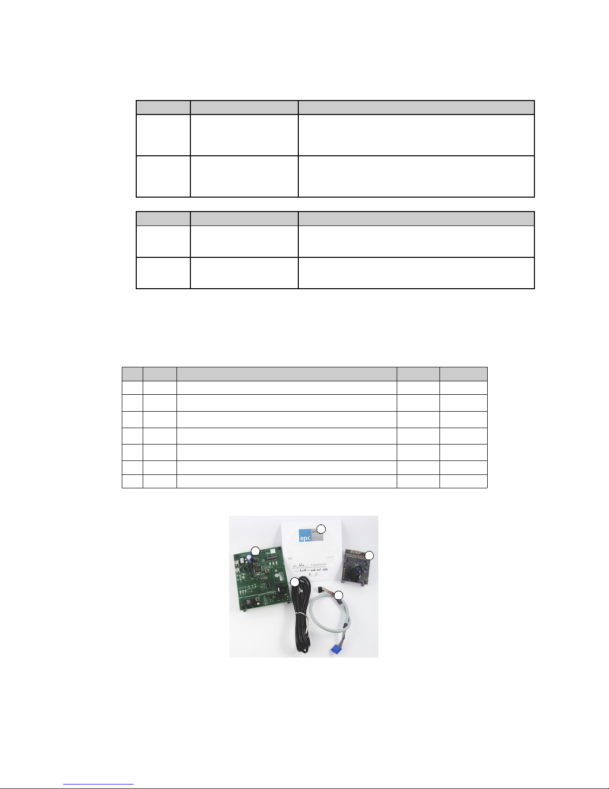
1.2. Scope of delivery
No Pieces Designation Kit Camera
➀ 1 epc610 Camera Module V1.0 Yes Yes
➁ 1 Cable to connect the camera with the mainboard Yes Yes
➂ 1 epc600/610 Evaluation Kit mainboard Yes
➃ 1 USB type 2 cable to connect the mainboard to a computer Yes
➄ 1 CD-ROM with application software + documentations Yes Yes
1 Manual epc610 Camera Module V1.0; on CD-ROM; Yes Yes
1 Manual epc600/610 Evaluation Kit; on CD-ROM; Yes
1
2
3
4
5
Figure 5: Material of the complete kit
© 2014 ESPROS Photonics Corporation
Characteristics subject to change without notice
4 / 26 Manual epc610_Camera - V1.5
www.espros.ch
Page 5

1.3. System requirements for host computer
Description Personal computer system
Computer IBM PC or compatible Apple (Mac)
Operating system, minimum Windows XP or higher Mac OS X 10.7 (Lion) or higher
Graphics resolution, minimum 1024 x 768 pixel 1024 x 768 pixel
Hard-disk free space min. 50MByte min. 50MByte
CD-ROM drive yes yes
USB connection min. USB 2.0 full speed min. USB 2.0 full speed
Table 2: System requirements for the host computer
1.4. System requirements for the Evaluation Kit mainboard
The epc610 Camera Module 1.0 works in combination with the following Evaluation Kit mainboards:
■ epc600/610 Evaluation Kit mainboard V1.2 or higher
■ Evaluation Kit mainboard V2.0 or higher
1.5. Technical data epc610 Camera Module V1.0
Description Data Remarks
Type epc610 Camera Module V1.0
Sensor chip epc610; 8x8 pixel
Supply voltage +8.0V … +9.0V DC
+5.0V ±5%
typ. 25mA
max. 420mA
Power consumption max. 2.4W
Communication SPI interface (4-wire), max. 10Mbit/s max. cable length: 0.5m
Receiver: focal length f
0
2.1 mm
Receiver: f-stop 2.2
Operating wavelength (according label) 860nm ±65nm (near infrared) Caution:
This is an IR emitting system !
Optical output power 1 W peak
Optical modulation frequency 10 MHz, pulsed operation
Operating range 0 – 300 cm @ remission = 80% @ varying integration times
Dimensions (length x width x hight) 70 x 54 x 505mm
Temperature range; Humidity 0° … 45°C; 20% … 80% RH
CE certificate The Evaluation Kit is designed as a module level
device. Therefore it is not a CE certified device. It
is the users responsibility to operate the hardware
in compliance with the CE regulations.
RoHS Fulfills 2002/95/EC
Table 3: Technical data epc610 Camera Module V1.0
1.6. Support and technical contact
If you need more information, please contact us at [email protected].
© 2014 ESPROS Photonics Corporation
Characteristics subject to change without notice
5 / 26 Manual epc610_Camera - V1.5
www.espros.ch
Page 6
2. Hardware
The purpose of this section is to introduce to the user the epc610 camera module and the functional use of the epc600/610 Evaluation Kit.
2.1. Block diagram
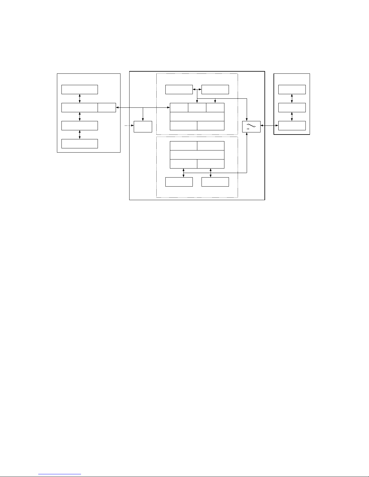
The system consists of 3 main parts: A personal computer, the Evaluation Kit mainboard and a camera module (refer to Figure 6).
Data
memory
Program
memory
USB
interface
2-wire / SPI
interface
I/O
interface
Main-microprocessor
Input switches
Main signaling
Power
supply
epc600 / epc610 evaluation system
epc600 application with PIC10F *
1-button interface
Microprocessor PIC10F206
ICSP connector
2-wire
interface
I/O
interface
Data
memory
Program
memory
Debug connector
Mainboard
Computer
Configuration-
& data files
Application Software
Human interface
GUI
USB
interface
Personal computer
USB
interface
Camera
Config setting
Optics
(optical path)
epc6xx
in operation
Figure 6: Block diagram (* not implemented)
The Personal computer
■ IBM compatible or Apple (Mac).
■ Man-machine interface for the operation and visualization of the evaluation system.
■ Runs the application software.
■ Stores, reads and writes configuration- and data-files for the application.
■ Host system for ST ARM 32bit Cortex microprocessor software development.
The mainboard
■ Two sections with independent microprocessor systems:
■ The one for the “epc600 / epc610 evaluation system” (Evaluation)
■ The second is a minimal hardware design concept for a Range Finder application with the epc600 (Application with PIC10F).
Not used for the epc610 camera application.
■ A main switch selects which section will be connected to the camera module.
■ The mainboard/system is connected to the computer by a USB cable for data communication and power supply.
■ The power supply generates all of the necessary supply voltages from the USB connection. An additional external USB power supply
can be added if the PC USB interface is not capable of delivering the necessary power (1'000 mA).
■ The “epc600/epc610 evaluation system” section supports and gives access to the full functionality of the epc610 devices.
■ Checks for the correct device identification of the camera.
■ Configures and controls the camera.
■ Reads the picture data from the camera and sends it via USB to the computer.
■ Provides configuration DIP switches and signaling LEDs.
■ A “debug connector” allows advanced users to download their own application. For more information, refer to the manual of the
corresponding processor.
The epc610 camera module
■ Is a fully functional module with the epc610 TOF Imager chip and optics combined.
■ Connects to the mainboard for power supply, data communication and configuration reading.
Goals and objectives of this Evaluation Kit:
■ Easy-to-use, plug and play demonstrator to show how epc's TOF products work and which possibilities they offer.
■ Test kit for engineers, allowing for a first contact with epc's products.
■ Reference design kit for design and development engineers.
■ Supports the user during development and testing of his own hard- and software.
© 2014 ESPROS Photonics Corporation
Characteristics subject to change without notice
6 / 26 Manual epc610_Camera - V1.5
www.espros.ch
Page 7

Exceptions of this kit:
■ The kit is a demonstrator. It is not designed for verification of datasheet parameters. Such tests need a dedicated test environment.
■ Not designed for use in final applications.
© 2014 ESPROS Photonics Corporation
Characteristics subject to change without notice
7 / 26 Manual epc610_Camera - V1.5
www.espros.ch
Page 8
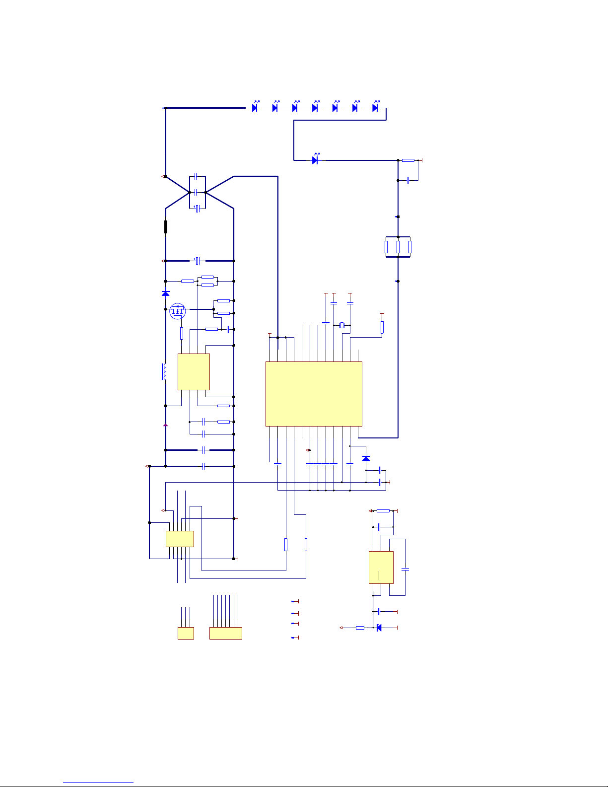
2.2. Schematics
MOSI1VDDCORE2VDDT3VDDM4VREF5VDDBS6VDDIO7VDDPX8VDDHPX9VDD10VDDCP11LED
12
NC1
13
NC2
14
XTAL115XTAL2
16
VDDPLL
17
MISO
18
nSS
19
SCLK
20
GND
21
GNDA
22
GNDLED
23
GNDPLL
24
epc610
IC1
epc610
GND
GND
GND
8V5
MISO MOSI
SCLK nSS
GND
18V_LED
MOSI
nSS
SCLK
MISO
X1
4.000 MHz
GND
GND
GND
C7
18p
C9 18p
C12
100n
5V
GND
1 2
3 4
5 6
7 8
9 10
11 12
J1
Milligrid 2x6
XT1
XT2
VIN
1
VOUT
2
C+
3
C-
4
GND
5
SHDN
6
IC3
LTC1983-5
-5V
C17
100n
-5V
Imax = 0.9A
D3
B340 40V 3A
0R1
R4
FB
3DR6
Isen
1
AGND
4
Vin8COMP
2
PGND
5
FA/SD
7
IC4
IC LM3478
G
S
D
T1
PMV45EN
+18V
600 R @ 100 MHz
L3
100nF
C23
47uH
L1
22k
R16
47k
R5
4k7
R6
15k
R7
10uF
C22
10nF
C24
100R
R8
22k
R9
1nF
C20
10nF
C21
0R1
R18
0R1
R17
D4
SFH4059D5SFH4059D6SFH4059D8SFH4059D9SFH4059
D10
SFH4059
D11
SFH4059
D7
SFH4059
22R
R21
22R
R23
22R
R25
0R
R22
4k7
R24
C5
1uF/50V
C1 1uF/50V
4.7uF
C4
4.7uFC6
4.7uF
C8
10uF
C3
10uF
C25
D1A
BAT74
100nF
C10
C26
1uF/50V
0R
R30RR11
10uF
C19
10uF
C13
C27
1uF/50V
10nF
C11
10k
R15
GNDGND
220uF
C18
GND
220pF
C14
GND GND
J7
J8
J9
GND GND
J10
J6J5
J2
1234567
J4
Debug
GND
GND
8V5
5V
MISO
SCLK
nSS
MOSI
TEST
TEST
MODE
MODE
123
J3
Header 3
RF1
470R
GND
DF1
BZX84-C5V6
8V5
Figure 7: Schematic epc610 module
© 2014 ESPROS Photonics Corporation
Characteristics subject to change without notice
8 / 26 Manual epc610_Camera - V1.5
www.espros.ch
Page 9
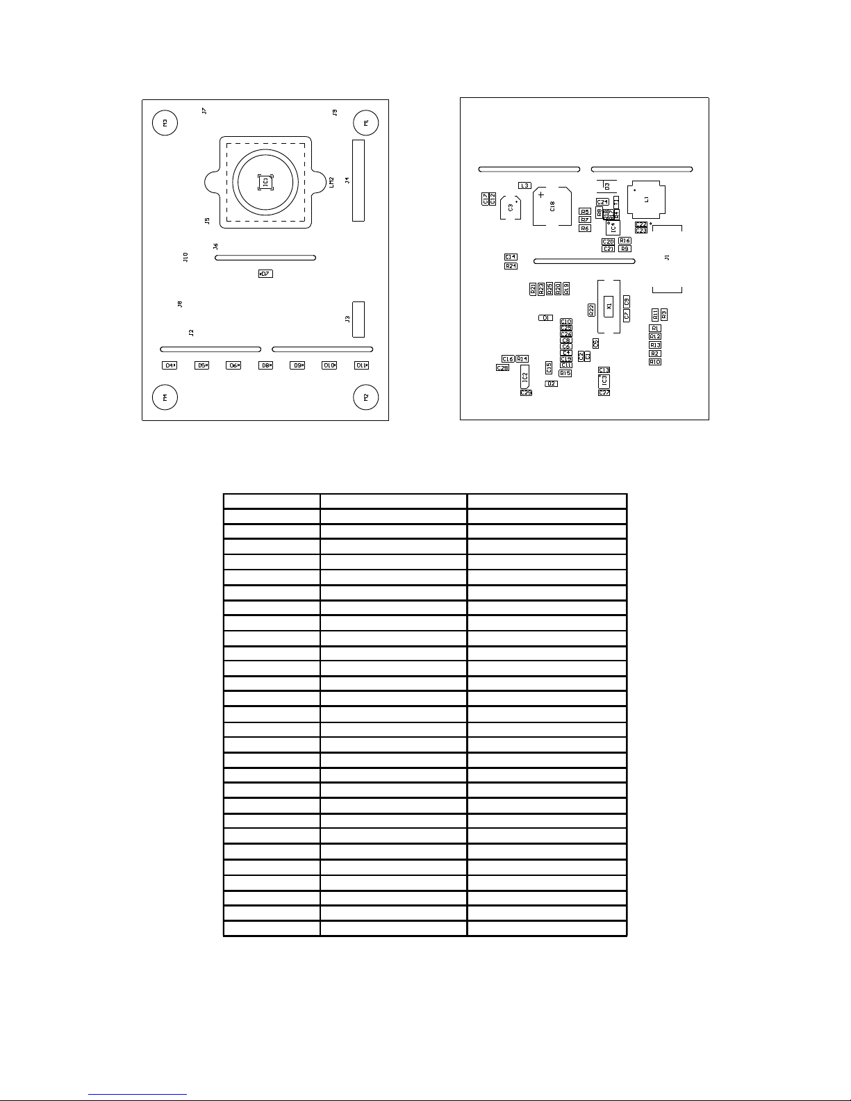
2.3. Assembly & part list
Figure 8: Camera board: Frontside assembly Figure 9: Camera board: Backside assembly
Note: For pixel field orientation refer to chapter 5.1.4.: Pixel field orientation.
18 pF Capacitor C7, C9
220 pF Capacitor C14
1 nF Capacitor C20
10 nF Capacitor C11, C21, C24
100 nF Capacitor C10, C12, C17,C23
1 μF Capacitor C1, C5, C26, C27
4.7 μF Capacitor C4, C6, C8
10 μF Capacitor C3, C13, C19, C22, C25
220 μF Capacitor C18
SFH4059 LED D4, D5, D6, D7, D8, D9, D10, D11
BAT74 Schottky double diode D1
B340 40V 3A Diode D3
PMV45EN Transistor T1
epc610 epc610 IC1
LTC1983-5 Voltage convertor IC3
LM3478 Voltage regulator IC4
Header, 6-Pin, dual row J1
47 μH Inductor L1
600 R @ 100 MHz Inductor L3
0 Ohm Resistor R3, R11, R22
0.1 Ohm Resistor R4, R17, R18
22 Ohm Resistor R121, R23, R25
100 Ohm Resistor R8
4.7 kOhm Resistor R6, R24
10 kOhm Resistor R15
15 kOhm Resistor R7
22 kOhm Resistor R9, R16
47 kOhm Resistor R5
4.0 MHz Quartz crystal, SMT X1
Milligrid 2x6
Table 4: Camera board: part list
© 2014 ESPROS Photonics Corporation
Characteristics subject to change without notice
9 / 26 Manual epc610_Camera - V1.5
www.espros.ch
Page 10

2.4. Hardware of the camera
The electronics of the camera module contains the epc610 chip, the buffering of the supply voltage, the crystal for the chip clock, 7 IR
emitter LEDs and a connector for the cable to the mainboard. The board incorporates a lens holder with the receiver lens.
2.5. Camera connector J1
Pins 11 and 12 must be terminated, but not necessarily in the camera module. If they are not terminated, the Evaluation Kit reads back the
chip type in software and terminates them according to the signals MODE and TEST.
For camera modules supplied by ESPROS photonics, the pin assignment is already done for the correct operation of the module in combination with the mainboard.
For the correct standalone operation of the epc610 camera module, the signals need to be terminated according to the Table 5 and the
datasheet epc610.
Pin Pin assignment
1 +5V
2 +5V
3 GND
4 +8.5V
5 SCLK
6 SDATA
7 GND
8 GND
9 MISO
10 MOSI
11 VDDM: Connect to +5V
12 VDDT: Connect to +5V
Table 5: Pin assignment camera connector J1
3. Evaluation Kit mainboard
For the technical description of the Evaluation Kit mainboard, refer to “Manual – epc600/610 Evaluation Kit – mainboard”.
© 2014 ESPROS Photonics Corporation
Characteristics subject to change without notice
10 / 26 Manual epc610_Camera - V1.5
www.espros.ch
Page 11
4. Setup & installation
4.1. Software installation
The enclosed CD contains all necessary application files and drivers to install and run the evaluation system on your computer.
4.1.1. SW installation on PC
System requirements (refer also to Table 2): PC with Windows XP or higher
Before you start the installation process, close all running applications.
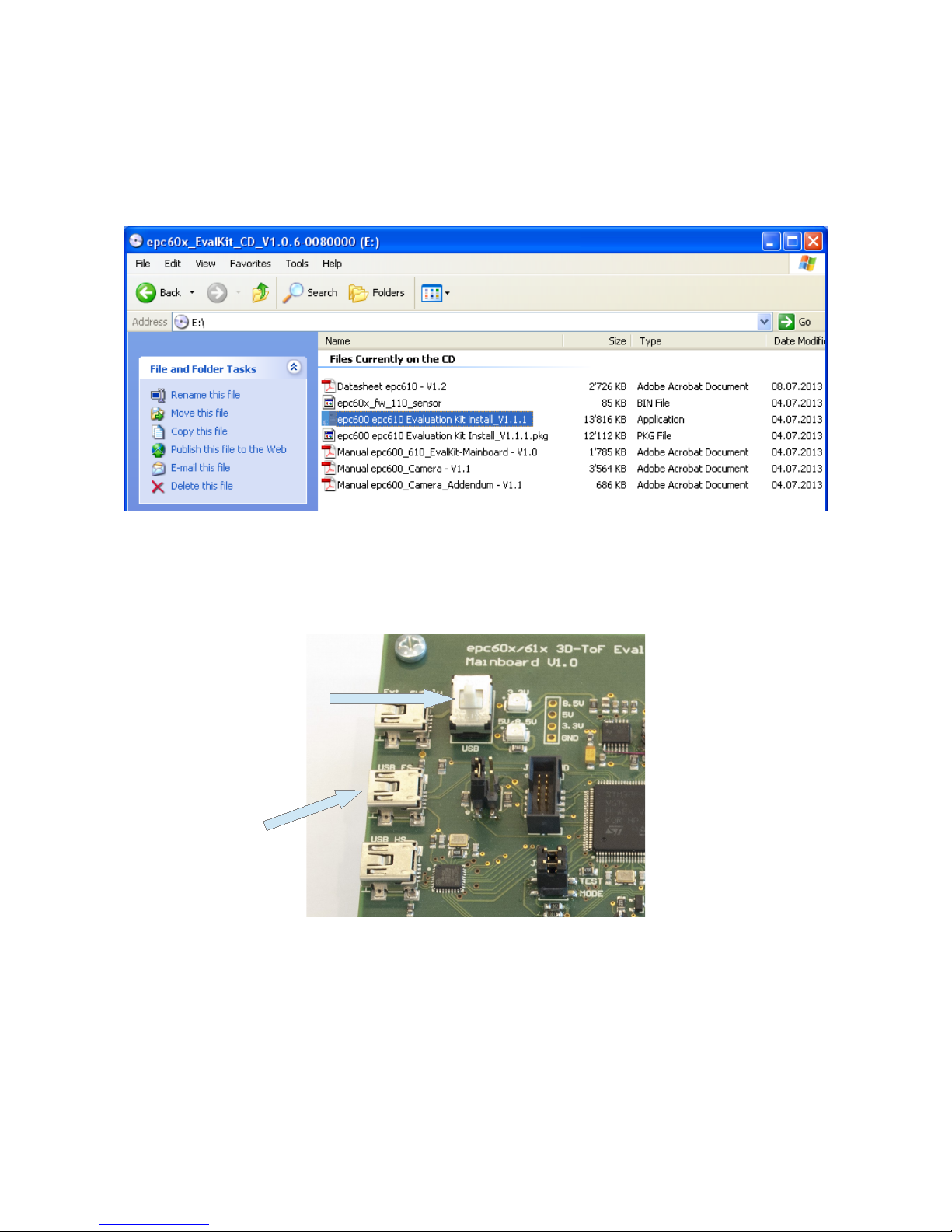
Figure 10: PC installation file on CD
Start the installation by executing the installer “epc600 epc610 Evaluation Kit Install_Vx.x.exe”.The installer routine will load the application
software as well as the necessary drivers on your system.
After completion of the software installation, connect the evaluation kit through the connector J6 USP FS to your PC with the enclosed
USB cable. Make sure that the power supply selection switch on the evaluation kit is switched to “USB” ( Figure 11).
Figure 11: PC USB power supply setting
The PC will detect the new hardware and start the Windows hardware installation assistant. Choose the default option “Install software automatically” to complete the installation.
Start the application with the link “epc600 epc610 Evaluation Kit” that has been added to your program shortcut menu.
Disconnect the USB cable before attaching a camera module and proceed with chapter 4.2. Running the epc610 application.
© 2014 ESPROS Photonics Corporation
Characteristics subject to change without notice
11 / 26 Manual epc610_Camera - V1.5
www.espros.ch
PC USB
Power Supply
Switch to
“USB”
Page 12
4.1.2. SW installation on Mac
System requirements (refer also to Table 2): Mac OS X 10.6 or higher
Before you start the installation process, close all running applications.
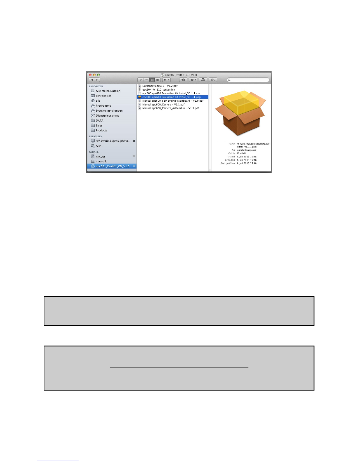
Copy the installer file “epc600 epc610 Evaluation Kit Install_Vx.x.pkg” from the CD to the desktop. Start the installation by executing the in staller “epc600 epc610 Evaluation Kit Install_Vx.x.pkg”. The installer routine will load the application software as well as the necessary
drivers on your system. Delete the installer file after successful installation.
Figure 12: Mac installation file on CD
After completion of the software installation, connect the evaluation kit through the connector J6 USP FS to your PC with the enclosed
USB cable. Make sure that the power supply selection switch on the evaluation kit is switched to “USB” ( Figure 11).
Start the application with the link “epc600 epc610 Evaluation Kit” that has been added to your program folder.
Notice:
The USB driver or the Evaluation Board can hang-up due to insufficient current driving capability. In this case, connect an external supply
for powering the Evaluation Board.
Disconnect the USB cable and proceed with chapter 4.2. Running the epc610 application.
4.2. Running the epc610 application
This mode is the actual developer mode which gives access to the full functionality of the epc610 camera module.
It requires a host PC that has the application software installed and running. Check if the application software is installed correctly on the
personal computer according to chapter 4.1.: Software installation. The software release must be the one delivered with the camera or
higher.
System requirements for the Evaluation Kit mainboard
■ epc600/610 Evaluation Kit mainboard V1.0: Use only with the extra add-on kit to extend the power supply of the board (see Figure 13).
■ Evaluation Kit mainboard V2.0 or higher
Caution:
The board must be in the unpowered state when the camera is connected to the mainboard and switch SW2 is changed!
Otherwise the board or camera may be damaged.
Connect the camera module to the cable and the other side of the cable to the mainboard.
Remark:
EACH CAMERA COMES WITH ITS OWN CALIBRATED FIRMWARE.
After a change of the camera, the upload of the corresponding firmware is necessary to operate it correctly.
The firmware is on the CD enclosed in the camera package. Refer to chapter 5.1.13. Firmware settings (Widget “Settings”).
Set the operation switch SW2 to “Evaluation”. (See Figure 13). This will set the evaluation system into the epc610 evaluation mode and allows for the operation through the application software on the computer.
© 2014 ESPROS Photonics Corporation
Characteristics subject to change without notice
12 / 26 Manual epc610_Camera - V1.5
www.espros.ch
Page 13
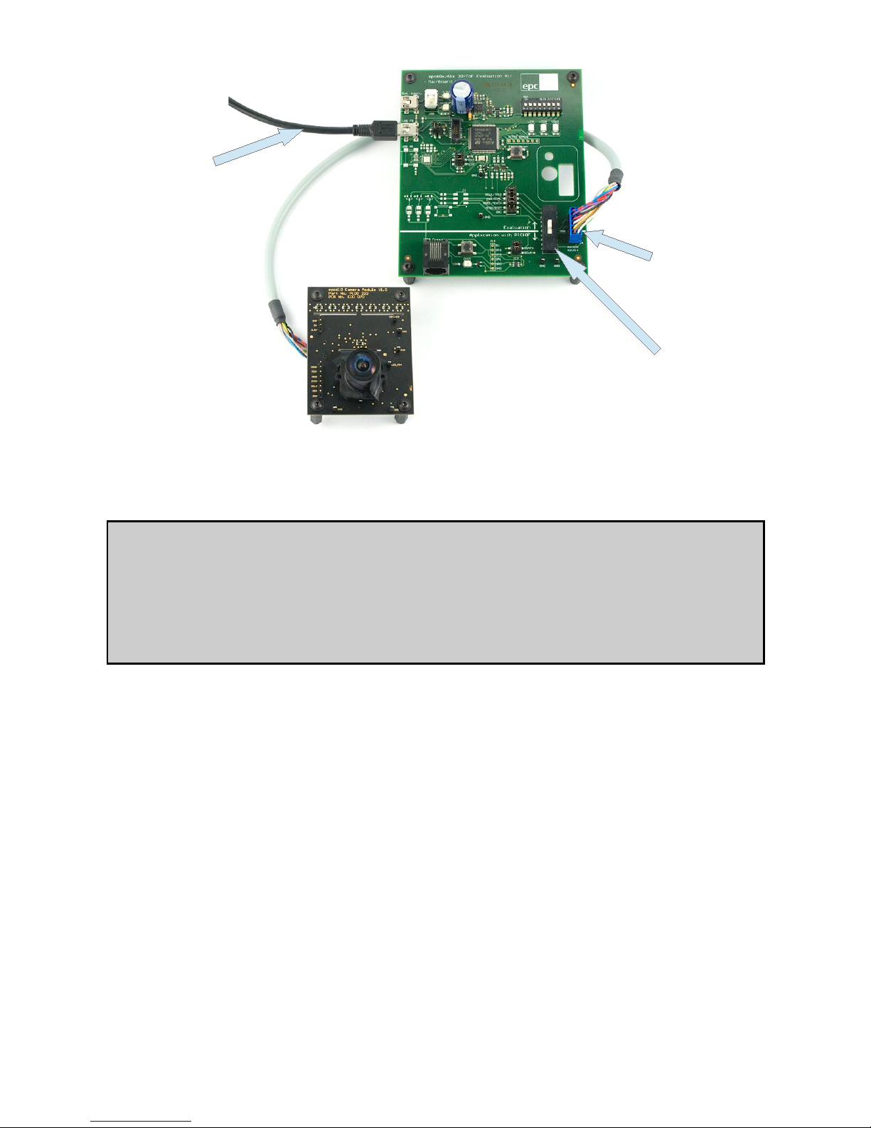
Figure 13: Hooking up USB connection and camera module
Connect with the USB cable the computer to the Evaluation Board. The board is now powered up by USB.
Advise:
For stable operation under any condition, we suggest to use an external USB power supply (1'000mA)
Notice:
The USB driver or the Evaluation Board can hang-up due to insufficient current driving capability.
In this case, connect an external supply for powering the Evaluation Board.
Please read the chapter “Board supply” of the mainboard manual if you are unfamiliar with the power supply options.
On power up, the system loads the microprocessor software and checks which type of camera module is connected. The system configures itself automatically according to the connected camera module.
Start the application software on your computer and press the “Connect” button on your main screen to connect the application software to
the evaluation system.
Press the button “Start” to start the evaluation software.
Refer to next chapter 5. Software “epc610 evaluation system” and user interface for detailed operating instructions.
© 2014 ESPROS Photonics Corporation
Characteristics subject to change without notice
13 / 26 Manual epc610_Camera - V1.5
www.espros.ch
Camera
connector
Switch needs
to be set to
“Evaluation”
PC USB
Power Supply
Page 14
5. Software “epc610 evaluation system” and user interface
5.1. Overview
This chapter describes the epc600/610 Evaluation Kit software (SW) and graphical user interface (GUI). The user interface is designed as
a dialog based application. The software operates the epc610 camera module, reads the data delivered by the module and allows for data
logging.
The 8x8 pixel array camera epc610 with the SPI interface works as a 3D TOF camera on-chip.
5.1.1. User Interface Overview
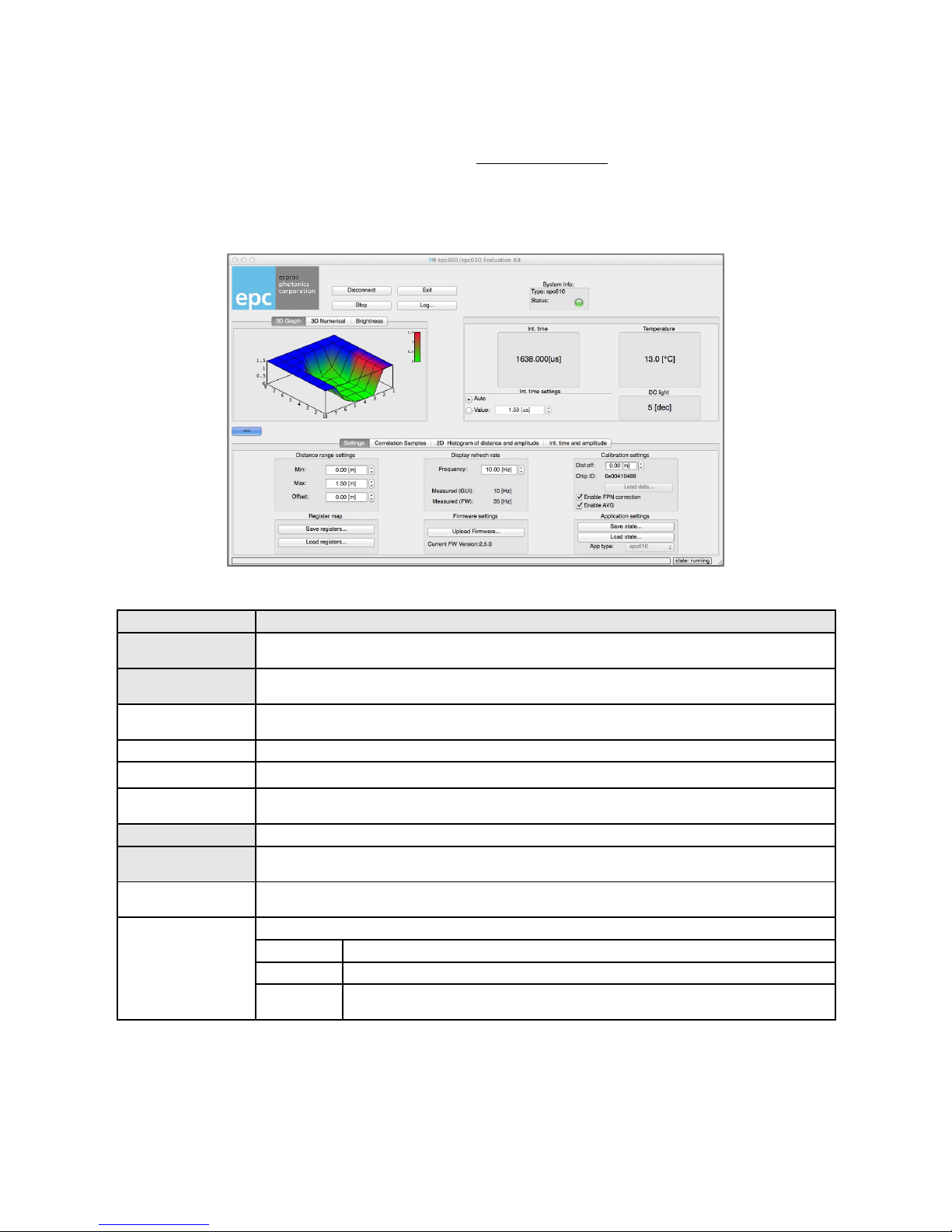
Figure 14 shows a snapshots of the user interface. All the windows are identical both for the Mac and PC. Table 6 provides a brief description of the different user interface elements.
Figure 14: User Interfaces epc610 application software
Area Description
Logo area epc logo, a double-click opens the “About” dialog”
Main button group Buttons for the basic handling of the system:
Connect / Disconnect Connects / disconnects the application to / from the Evaluation Kit hardware. Always use this first before you
start any other operation.
Start / Stop Starts or stops the data acquisition. Use after the Evaluation Kit hardware has been connected.
Exit Quits the application.
Log Data logging for offline analysis.
A dialog window allows the selection of log data and file type.
App. Type Shows the type of the connected camera module.
System info This group shows the camera system type and the status of the system with a LED symbol:
Type Shows the type of the connected camera system (epc600 or epc610). This information is read from the con -
nected camera module.
Status Signals the status of the connected camera system with a LED symbol:
● grey The system is not connected yet.
● green The system is connected. No warnings or errors are discovered.
● red The system has entered an error state.
The root-cause of the error is shown in a pop-up box.
Table 6: Functionality of the basic application layout
© 2014 ESPROS Photonics Corporation
Characteristics subject to change without notice
14 / 26 Manual epc610_Camera - V1.5
www.espros.ch
Page 15
Area Description
3D Graph This widget represents the 3D TOF measurement values in 3D look.
3D Numerical The 3D TOF pixel values as numbers and quality information as colored background in this widget.
Brightness Widget of the black & white picture with the ambient illumination only (no self-illumination).
Integration time dialog The dialog holds the switch that allows for either the setting of the integration time manually or to have the in -
ternal algorithm automatically set the integration time. The respective value for the integration time is dis played.
This dialog also holds the display fields for the temperature and DC light. This data, like the distance and am plitude values, is delivered from the TOF chip.
Button With this button, the visibility of extended user interface elements can be toggled.
Settings The widget for user interface parameter setting and firmware upload.
Distance range settings Used to set a fixed position offset and measurement range limit.
Register map Save and loading chip registers (for support purposes only).
Display refresh rate Settings for the refresh rate on the display.
Firmware settings Upload of new or corresponding firmware versions for the camera to the Evaluation Kit hardware.
Calibration settings Displays chip ID and additional distance offset.
Application settings Save and load user interface settings.
Correlation Samples The widget displays all the DCSx values.
2D Histogram of distance and amplitude
The widget shows the numbers and the histogram distributions for the 3D TOF distance values and the ampli tude values.
3D modes: readout amplitude
“Brightness” mode: normalized amplitude scaled to the integration time and the “Grayscale resolution”
Int. time and amplitude The widget shows per pixel the used integration time and the readout amplitude values as numbers and his -
togram distributions.
Table 6 cont: Functionality of the basic application layout
5.1.2. Basic operation
Before any measurements can be taken, the data link between the camera module and the mainboard needs to be established by pressing the “Connect” button. If the camera module is detected, the status indicator LED in the “System Info” section will be green and the type
of camera module is displayed in this section. The actual measurement can now be started with the “Start” button.
The measurement runs continuously and the values will be displayed in real-time. For offline data processing, there is a logging option
available. The “Log...” button will open a dialog window that allows setting of specific logging options and to start the logging.
Note:
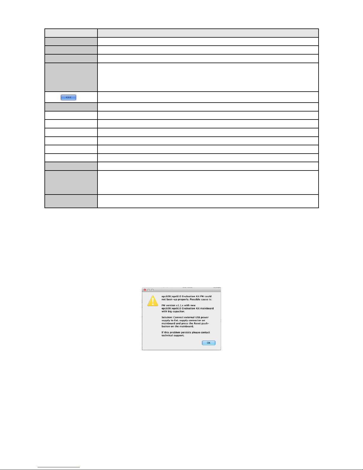
If the following pop-up window appears after “Connect”:
Figure 15: FW boot-up
Reason:
You are using a 1st series camera module with a V1.2 or V2.0 mainboard. The USB power supply is not compatible
Solution:
Use an external 1'000mA USB supply. Connect it to the appropriate plug on the mainboard and switch to „Ext.“ power supply. After pow er-up press the reset button on the mainboard.
© 2014 ESPROS Photonics Corporation
Characteristics subject to change without notice
15 / 26 Manual epc610_Camera - V1.5
www.espros.ch
Page 16
5.1.3. Control widgets
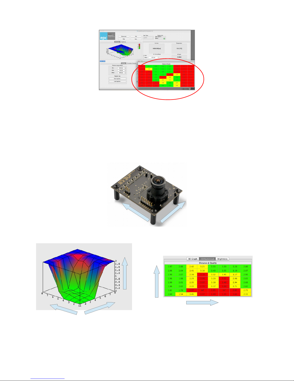
Figure 16: User Interfaces with a popped out widget
“3D Numerical”: Distance & Quality” (red marked area)
Control widgets are the basic units of the application for input and out dialogs.
They can be selected either inside the control area by pressing the corresponding button or popped out of the main dialog as a standalone
window by drag and drop of the tab button (press the tab and pull it out). This way the dialog is popped out with selected control widget.
Each control widget can be visible or accessible once. A closing of the external dialog puts back the control widget to the tabs of its control
area.
5.1.4. Pixel field orientation
The pixel field corresponds to the numeration of the graphical widget “3D Numerical” presentation. Pixel 1/1 is at the lower left corner of
the sensor with optics.
Sensor orientation
corresponding 3D graphic representation corresponding numeric representation
Figure 17: Pixel field orientation with optics: Pixel 1/1 is at the lower left corner
© 2014 ESPROS Photonics Corporation
Characteristics subject to change without notice
16 / 26 Manual epc610_Camera - V1.5
www.espros.ch
Rows
Rows
Rows
Columns
Distance
Columns
Columns
Pixel 1/1
Pixel 1/1
Pixel 1/1
Page 17
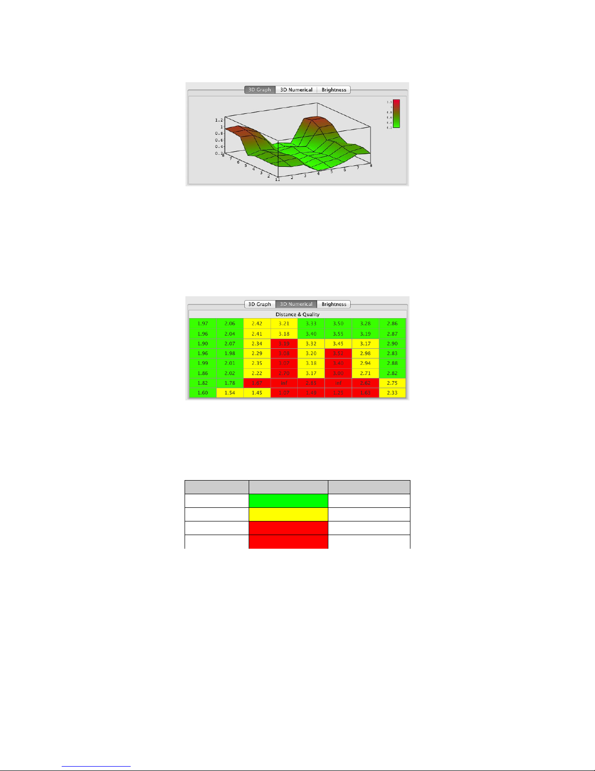
5.1.5. Widget “3D Graph”
This is a real-time 3D representation of the 3D TOF distance data. The basic scaling is given by the “Setting / Distance range setting”.
Figure 18: 3D TOF distance plot
The blue color (see Figure 17) indicates that the object is out of range: too far or too dark (no signal; corresponds to “inf” in “Distance and
Quality” widget).
Place the cursor in the widget area and press the left mouse button for turning and flipping the 3D view. The scroll wheel zooms up and
down the graph.
This widget works only if a distance measurement mode is selected: “3D Graph” or “3D Numerical”.
5.1.6. Widget “3D Numerical” (Distance and quality)
Figure 19: 3D Numerical: Distance and quality table
This 2D graph presents per pixel the 3D TOF distance value.
The value “inf” indicates, an object is out of range: too far or too dark (no signal).
The background color reflects the quality of the pixel signal:
Signal quality Background color Readout amplitude
excellent green 200 < value
good yello 100 < value < 200
bad red value < 100
infinity inf value < 50
Table 7: Signal quality
This widget works only if a distance measurement mode is selected: “3D Graph” or “3D Numerical”.
5.1.7. Integration time and temperature dialog (Widget “3D Graph” and “3D Numerical“)
This dialogue belongs to the widgets “3D Graph” and “ 3D Numerical”.
When set to automatic mode, the ec610 camera selects always the most reliable result out of an exposure sequence with the integration
times 1.6μs / 205μs / 1.6ms. The highest integration time corresponding to the selected values is displayed in real time and is continuously
adjusted to get the optimal measurement result. Refer to the epc610 datasheet for more information on integration time and how to adjust
it.
© 2014 ESPROS Photonics Corporation
Characteristics subject to change without notice
17 / 26 Manual epc610_Camera - V1.5
www.espros.ch
Page 18
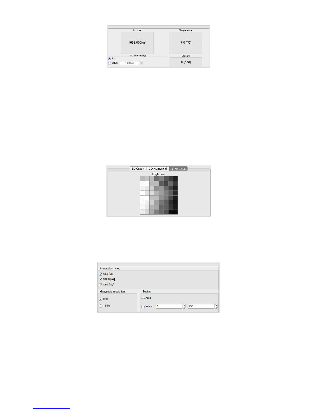
Figure 20: Integration time and Temperature dialog
For some test setups, it may be useful to set the integration time manually. This can easily be done by typing the desired time in the value
window or by using the scroll arrows. The integration time will remain at this value until manually changed again.
The temperature and DC light values (ambient-light values) are also continuously read from the epc610 chip and displayed as uncalibrated
data. These values are used for compensation of the distance data as explained in chapter 5.1.14: Calibration settings (Widget “Settings”).
An actual user application may require different read rates of these values.
5.1.8. Widget “Brightness” (Grayscale image)
The “Brightness” view actually allows to take a grayscale image of the scene. It is the black & white picture with the ambient illumination
only (no self-illumination) in the near infrared 860nm. The pixels reflect in the “Auto” mode the normalized amplitudes and in the “Value”
mode the regular grey-scale picture.
Note:
Be aware in the “Auto” mode, only sceneries with high contrast aspect ratios are shown as they are for viewer’s eye e.g. an edge between
a white and a black area. Uniform surfaces are magnified in contrast the way having minimum one pixel white and one black and look not
anymore evenly.
Refer for details to next chapter 5.1.9. Integration time and Greyscale resolution (Widget “Brightness“) .
Figure 21: Brightness picture
This widget works only if the “Brightness” mode is selected.
5.1.9. Integration time and Greyscale resolution (Widget “Brightness“)
This dialogue belongs to the widget “Brightness”.
Figure 22: Integration time, Grayscale resolution and Scaling
The algorithm is using the marked up integration times to find best quality of pixel values to build the picture.
The “Grayscale resolution” belongs in the brightness mode to the Widget “2D Histogram of distance and amplitude” and selects the repre sentation of the numerical values in an 8 or 16 bit way.
The scaling mode “Auto” spreads the black & white picture in the adaptive way that the lowest measured DC light value appears as a black
pixel and the highest as a white pixel e.g. for 8 bit scaling: lowest = 80 to black, highest = 180 to white.
Note:
Be aware in this mode, only sceneries with high contrast aspect ratios are shown as they are for viewer’s eye e.g. an edge between a
white and a black area. Uniform surfaces are magnified in contrast the way having minimum one pixel white and one black and look not
anymore evenly.
© 2014 ESPROS Photonics Corporation
Characteristics subject to change without notice
18 / 26 Manual epc610_Camera - V1.5
www.espros.ch
Page 19
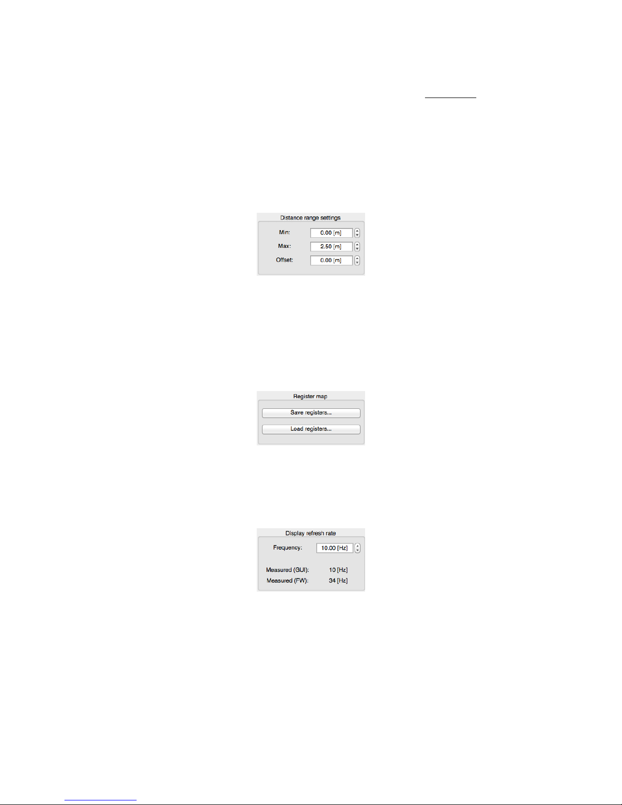
The scaling mode “Value” is a regular black & white picture representation. It spreads (like a zoom) only the selected segment of measure ment values in the way that the set low value appears as a black pixel and the high as a white pixel e.g. for 8 bit scaling: left value = 0 to
black, right value = 255 to white. He can choose his own fixed span and levels of representation.This mode might be helpful in combination
with the integration time selection to find special patterns in the picture.
The scaling uses the formula
scaled_amplitude = scale_span ⋅log2(readout_amplitude⋅
2
8
2
integration_time_index
)
Normalized amplitude: scaled_amplitude
Readout amplitude: readout_amplitude
Scaling value: scale_span (based on the factors “Scaling”
5.1.10. Distance range settings (Widget “Settings”)
The settings affect only the user interface and do not have any influence on the epc610 chip. They are intended to set a fixed offset value
and “zoom-in” on an operational point. The “zoom” effect will become visible in the “3D Graph”.
Figure 23: Integration time and temperature dialog
5.1.11. Register map (Widget “Setting”)
This is a service function for epc's customer support. It is not transparent to the user.
Save registers:
On request of epc's customer support, the user can read the set of the epc610 registers and store it on the computer in a coded file format.
For support, he can send later on this file together with the application settings per e-mail to epc. “Application settings” file (see below) and
chip registers can give epc's customer support a good insight to help the user debugging the system.
Load registers:
Register files from epc's customer support can be uploaded to the chip on it's request.
Figure 24: Register map
5.1.12. Display refresh rate (Widget “Setting”)
Just like the distance rate settings in the chapter before, the display refresh rate setting only affects the user interface on the host comput er. However, for informational purposes, the approximative data refresh rate is displayed as well. This provides information on the actual
“frame rate” delivered by the chip. Naturally, this value will strongly depend on the integration time.
Figure 25: Integration time and temperature dialog
© 2014 ESPROS Photonics Corporation
Characteristics subject to change without notice
19 / 26 Manual epc610_Camera - V1.5
www.espros.ch
Page 20
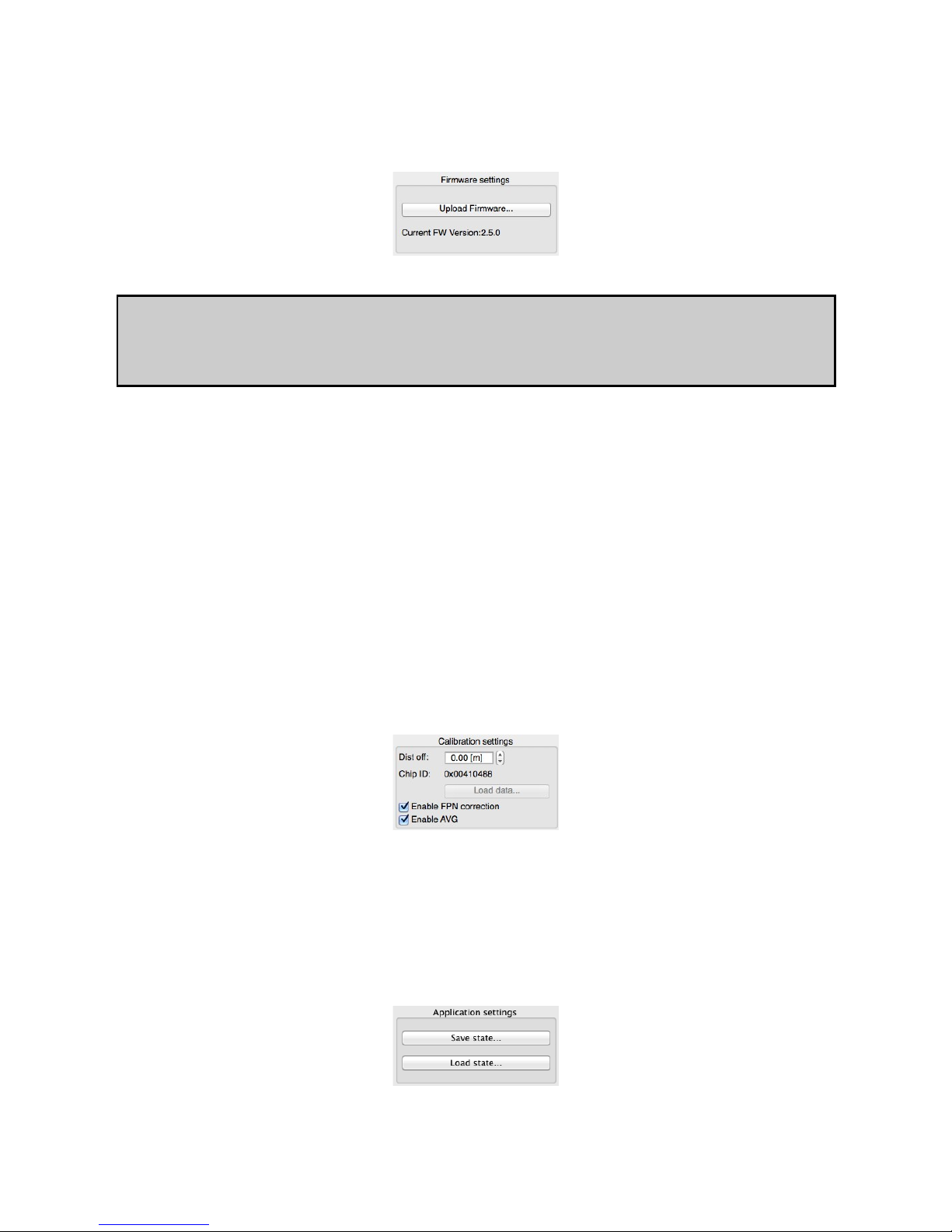
5.1.13. Firmware settings (Widget “Settings”)
The Evaluation Kit requires firmware that runs on the ARM controller. This firmware configures the chip, performs the measurements, cal culates the result values, interfaces to the computer software and much more. As the development around the epc TOF devices is ongoing, there will be regular updates of this software. By using the “Upload Firmware” button, it is possible to flash such updated versions on
the Evaluation Kit.
Figure 26: Firmware settings
Remark:
After a change of the camera, the upload of the corresponding firmware is necessary to operate it correctly.
Each camera has its own calibration parameters.
The firmware is on the CD enclosed in the camera package.
5.1.14. Calibration settings (Widget “Settings”)
3D TOF performance can be increased by calibration. There are several influencing factors on the 3D TOF performance. These factors
are:
• Fixed pattern noise
• Ambient-light (DC light)
• Temperature
• Target reflectivity
The epc TOF devices are designed to suppress ambient-light and to compensate for different target reflectivities internally. For many applications, the chip performance will be sufficient in these aspects. However, an additional external calibration will always improve accuracy.
Due to the extremely short timeframes that are relevant for TOF, there is an inherent temperature dependency that leads to a distance drift.
Therefore, the epc TOF chips have integrated temperature sensors whose readings can be used to offset this effect.
In order to deliver optimal performance, each epc610 camera module is calibrated in the factory. These calibration values can be loaded to
the Evaluation Kit with the “Upload Firmware...” button. Do this every time the camera module is changed. The absolute distance reference
can additionally be fine-tuned with the “Dist off” setting (distance offset).
Note:
The specific calibration data is provided by epc in the camera assigned firmware file and is specific to the respective chip whose ID is dis played in the Calibration Settings section.
Figure 27: Calibration settings
When set “Enable FPN correction”, the software applies a fix pattern noise correction per pixel to get a smoother 3D picture. It reduces de viations from pixel to pixel caused by manufacturing tolerances.
“Enable AVG” averages the distance data per pixel over several pictures to reduce noise.
5.1.15. Application settings (Widget “Settings”)
This dialogue allows the user, to save and reload user interface configurations. It simplifies the work with predefined user interface set tings.
Figure 28: Application settings
© 2014 ESPROS Photonics Corporation
Characteristics subject to change without notice
20 / 26 Manual epc610_Camera - V1.5
www.espros.ch
Page 21
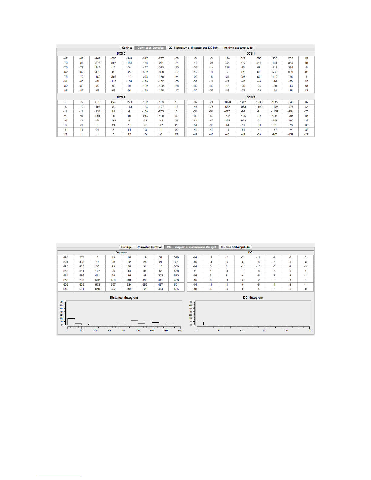
5.1.16. Widget “Correlation Samples”
Figure 29: The sample values of the 4 integration periods
3D modes:
This section lists online all the original DCSx sample values of the 4 integration periods belonging to 1 measurement cycle. They apply to
the distance and amplitude formula given in the Datasheet epc610, chapter “Distance measurement” and ”Quality of the measurement re sult”. For more details refer to the datasheet.
“Brightness” mode (Grayscale image):
The 4 datasets DCS0 - DCS3 are the amplitude values of the 4 sequential black & white pictures with ambient-light.
5.1.17. Widget “2D Histogram of distance and DC light”
3D modes:
The two tables list in digits the computed 3D TOF distance values and the readout DC light amplitude values.
The histograms below the tables indicate the distributions a certain values occurred in the pixel field.
Figure 30: Values and histograms of distances and DC light (3D modes)
© 2014 ESPROS Photonics Corporation
Characteristics subject to change without notice
21 / 26 Manual epc610_Camera - V1.5
www.espros.ch
Page 22
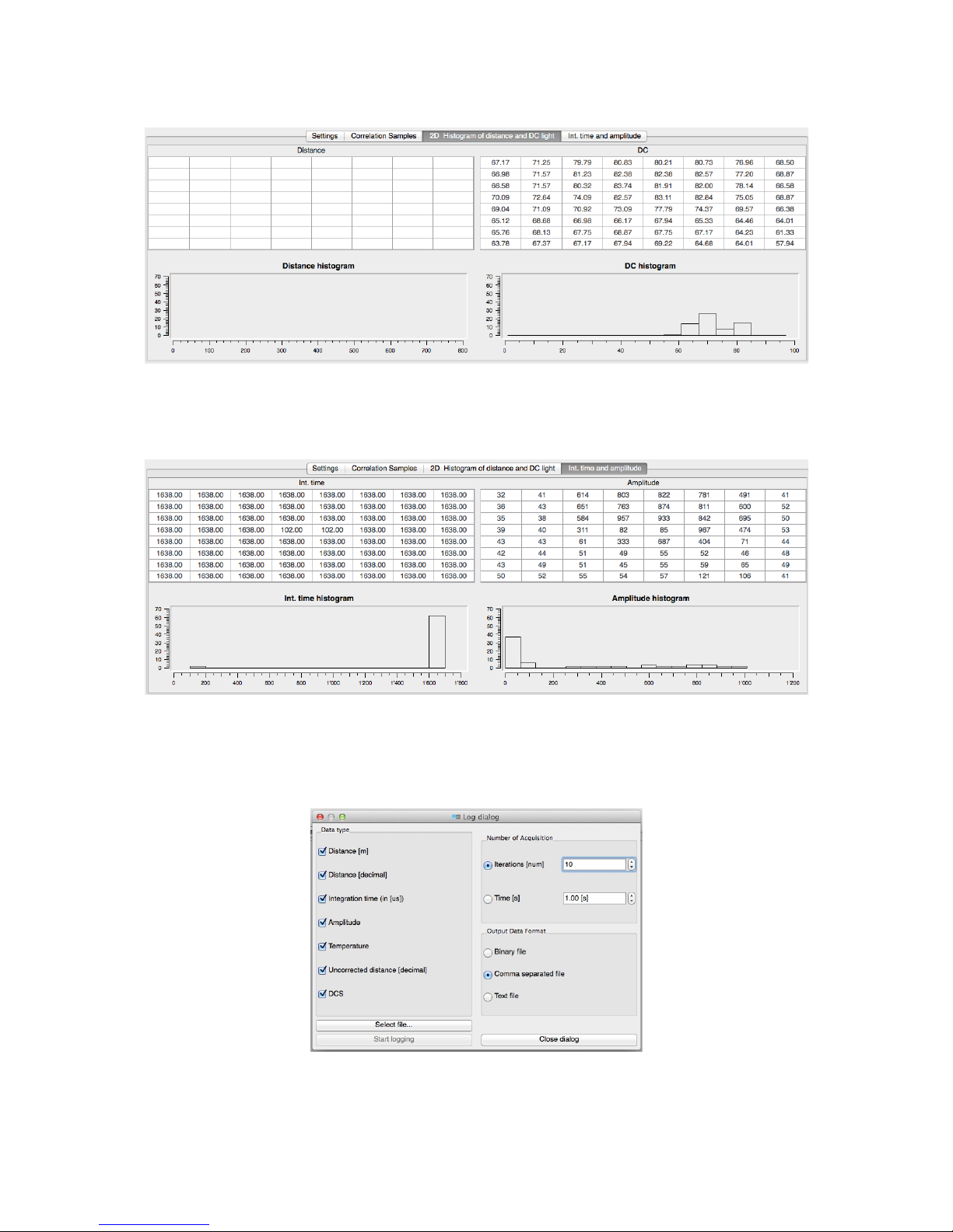
“Brightness” mode (Grayscale image):
The “Brightness” mode shows an empty distance table and the readout DC light amplitude values.
Figure 31: Values and histograms of distances and amplitudes (“Brightness” mode)
5.1.18. Widget “Int. time and amplitude”
The widget shows per pixel the used integration time and the calculated readout amplitude values as numbers and histogram distributions.
Figure 32: The sample values of the 4 integration periods
5.1.19. Log dialog
This function allows data logging for offline analysis of epc610 chip read-out data as well as corrected data. The data stream can be col lected either by number of measurement counts or by a logging time.
Figure 33: The log dialog
© 2014 ESPROS Photonics Corporation
Characteristics subject to change without notice
22 / 26 Manual epc610_Camera - V1.5
www.espros.ch
Page 23

5.2. Additional technical info and definitions
For the detailed technical description and specification of the epc610 chip, refer to the corresponding Datasheet epc610.
Below are some technical considerations to help better understand the working principles and boundary conditions:
Maximum AC input illumination power
This is the amount of the backscattered modulated light, that leads to a saturation of the signal processing path. The camera goes “blind”.
This value is also a function of the relative spectral sensitivity (e.g. refer in the datasheet to the table “Sensitivity and ambient-light sup pression vs. wavelength”).
Minimum AC input illumination power
This is the minimal amount of the backscattered modulated light to provide just enough signal. Below this level, the distance noise can in crease significantly. This value is also a function of the relative spectral sensitivity (e.g. refer in the datasheet to the table “Sensitivity and
ambient-light suppression vs. wavelength”).
Integration time
During this time, the sensor is sampling the light power. A longer integration time leads to a higher sensitivity of the camera. This means a
weaker illumination can be used. Use this to trade-off between achievable measurement range and illumination power.
Dynamic range at a fixed integration time
Is defined by the span between the maximum to minimum AC input illumination power limits.
Extended dynamic range
By an on-the-fly adaption of the integration time to the illumination conditions of the scenery, the dynamic range of the system can easily
expanded.
Unambiguity distance
epc TOF devices are operated with a periodically (e.g sinusoidal) modulated illumination. The unambiguity distance is the distance that
corresponds to the traveled distance of light within one modulation period. Light signals inside this time window can be allocated to a
unique distance. Reflected light with a longer travel time will cause false readings (because the sensor cannot distinguish between different modulation periods).
Illumination of the scenery
Is the light actively brought into the observation area by the camera's modulated light signal.
Remission (more commonly known as reflectivity)
The emitted light from the camera is backscattered by the object in the scenery. The surface conditions of this target define how much light
will be reflected. This loss of light power is defined by the remission factor (or reflectivity)
Examples: A sheet of white paper has a remission of 90%, whereas a dark carpet reflects only 5%.
Ambient-light suppression
In real world applications, there will always be ambient-light. The epc610 3D TOF Imager is designed to filter out such ambient-light from
the received signal (ambient-light suppression). This internal filtering capability works so well that the systems even operates in highly illuminated scenes such as outside applications in bright sunlight. However, there is a limit for this suppression. E.g. a measurement attempt ed directly towards the sun will fail because of saturation.
The ambient-light suppression also depends on the relative spectral sensitivity (e.g. refer in the datasheet to the table “Sensitivity and ambient-light suppression vs. wavelength”).
Distance offset
There is always a distance offset that is made up by the sum of all delays in the signal chain of the chip. Like any other camera system,
TOF systems need be offset-calibrated before they are put into use.
6. Further Application notes
6.1. Illumination
Good illumination is crucial, as is the design of the Rx and Tx lens system. epc provides several application notes on this topic. However,
an LED illumination subsystem and the matching Rx and Tx lens systems requires adequate experience.
6.2. Ambient-light & wavelength
Ambient-light is by nature a disturbing factor. There are several options to suppress such interferences in an application. One solution is
the use of modulated light, which can easier be separated from typical static (DC) ambient-light. Another widely used approach to increase
the ratio of the signal to the ambient-light is to work with specific wavelengths. Sunlight and artificial light sources typically have low in frared (IR) power. This is the reason why epc detectors have high sensitivities in the near infrared range (NIR). Sensor systems based on
epc detectors should therefore be designed to work in the NIR Range (e.g. 940nm).
6.3. Noise reduction
The accuracy of the distance readings depends on the signal amplitude in the receiver path. The higher this amplitude, the more accurate
the results, the less distance noise occurs. The signal amplitude is equal to the product of the received light energy multiplied by the inte gration time. The adaptation of the integration time to the highest possible signal values (including a certain safety margin to avoid channel
saturation) leads to noise reduced measurement values.
© 2014 ESPROS Photonics Corporation
Characteristics subject to change without notice
23 / 26 Manual epc610_Camera - V1.5
www.espros.ch
Page 24
6.4. Temperature compensation
The energy of light emitting devices and the sensitivity of photo-electric sensors both have a certain temperature dependency. If such sys tems are working under conditions with widely varying temperatures, a compensation of the measurement data as a function of temperature is necessary. The epc610 has internal temperature sensors that can be used for such compensations. For more details, refer to the
datasheet of the chip.
6.5. Linearity correction
The actual light modulation signal differs from the theoretical waveform. Therefore, the distance readings typically have some relative errors. The deviations depend on the distortion of the signal waveform by the hardware as well as on the signal amplitude in the receiver
path. Such non-linearities can be reduced by using a correction algorithm or look-up table as function of the distance and signal amplitude.
6.6. Special phenomena
Special phenomena can be created by time domain effects, reflections, surface behavior, etc. … Such phenomena mainly result from
changing conditions (illumination, reflectivity, fast movements..) during one measurement. Below are some examples.
6.7. Motion blurring (Fast moving objects)
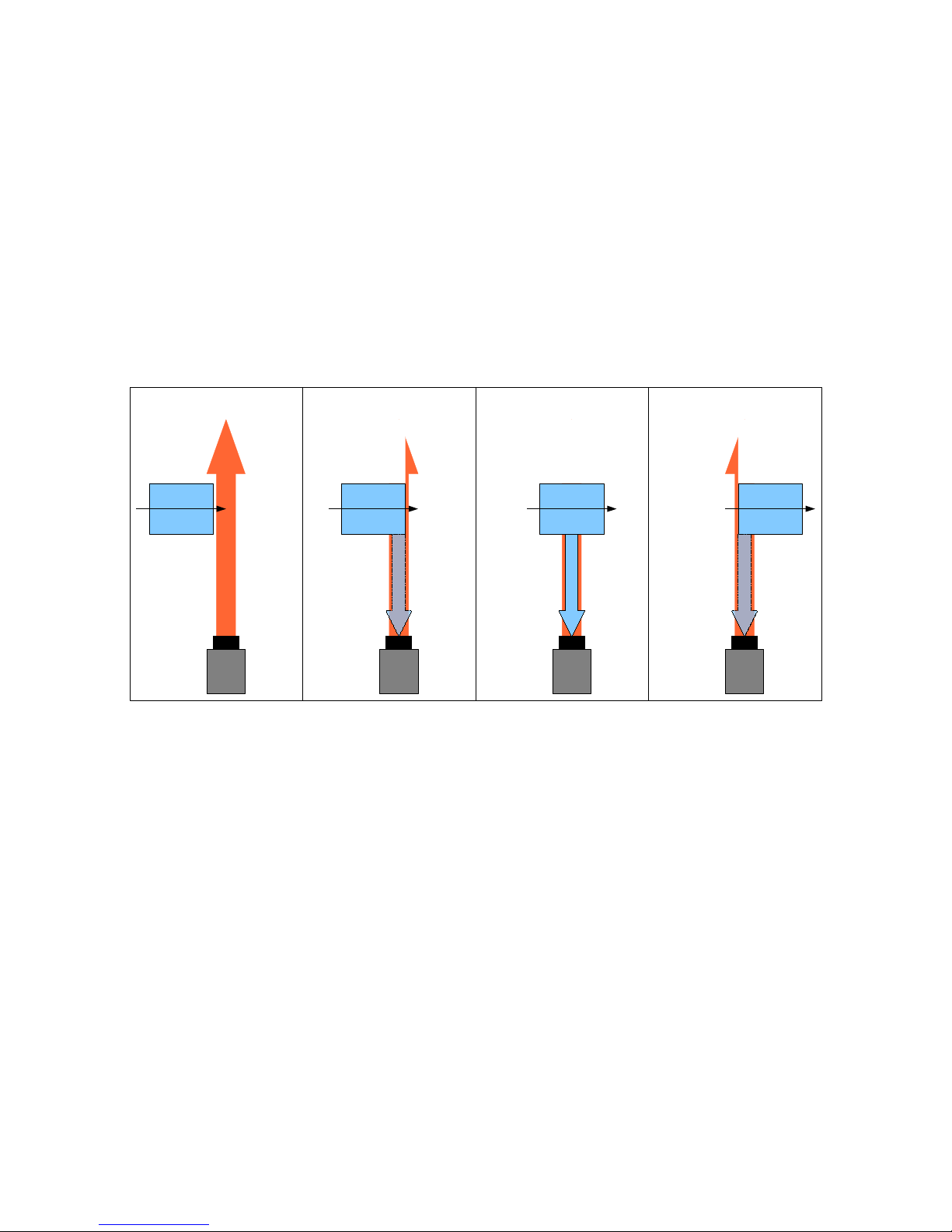
To get correct distance results, an object should not move in any direction faster than the camera needs to catch the 4 corresponding samples for one distance calculation. Faster movement leads to unstable or erroneous readings for a measurement sequence. Figure 34
shows an object crossing though the observation beam. At sample 1, any reflected light is missing due to the fact that the object does not
touch the light beam. Sample 2 and 4 see a reduced signal, because not all the light is reflected by the object. In fact, after the distance
calculation, the result is not reliable and needs to be scrapped.
CAMERA
MOVING OBJECT
EMITTED LIGHT
CAMERA
MOVING OBJECT
REFLECTED LIGHT
CAMERA
MOVING OBJECT
REFLECTED LIGHT
CAMERA
MOVING OBJECT
REFLECTED LIGHT
TIME T1
SAMPLE 1
TIME T2
SAMPLE 2
TIME T3
SAMPLE 3
TIME T4
SAMPLE 4
Figure 34: Measurement cycle with moving object
6.8. Transparent objects
Transparent objects may distort the distance reading as they partially separate the illumination. Some of the light is reflected directly and
another part may be reflected from objects after passing through the transparent surface. Depending on the ratio of these parts, the dis tance result may be inaccurate. Keep in mind that visually opaque targets can be transparent for infrared light.
6.9. Changing remission (reflectivity)
The measurement assumes that during a measurement cycle, the object does not change its reflectivity. Physically, this corresponds to 4
correlation samples with equal amplitude. If the remission of the object is changing during the sampling sequence, the amplitudes will mismatch and a distance error may occur.
6.10. Indirect light reflections
The measurement assumes that the emitted light is directly reflected back to the receiver. In real conditions, it may happen that the light
that comes back to the sensor returns by multi-point reflections (e.g. by mirroring objects in the background). The camera cannot distin guish between direct or indirect reflected light. Depending on the magnitude of such indirect reflections, such cases may lead to incorrect
distance readings.
6.11. Convex surfaces
If light is reflected from convex surfaces (e.g. a round pillar), the reflection magnitude strongly depends on the surface angle. At steeper
angles the reflected light is attenuated more .Therefore, such objects look smaller than they actually are.
6.12. Highly reflective background objects
Highly reflective objects in the background of a scene may mask an object in the foreground. While being farther away than the actual object of interest, they may return a higher amplitude signal due to their higher reflectivity. One option to tackle such situations is the reduction of the illumination power.
© 2014 ESPROS Photonics Corporation
Characteristics subject to change without notice
24 / 26 Manual epc610_Camera - V1.5
www.espros.ch
Page 25

6.13. Light scattering
This phenomenon happens if light is reflected multiple times between the sensor surface and the receiving lens system. It leads to blurry
and diffuse pictures of the object. Therefore, lens systems of industrial sensor systems typically have an anti-reflex coating. It is highly recommended to deploy such anti-reflex coatings for TOF based sensor systems as well.
7. Maintenance and disposal
7.1. Maintenance
The components of the evaluation kit do not need regular maintenance. A functional check is recommended each time the kit is taken into
operation:
■ Check the mounting position and the detection area of the sensor with respect to the operational conditions. Also check that there is no
hazardous situation.
■ From time to time, clean the sensor with a soft towel and with a little soapy water to remove dust or dirt.
7.2. Disposal
Disposal should be done using the most up-to-date recycling technologies for electronic components according to the local regulations and
laws. The design and manufacture of the kit's components are done in compliance with the RoHS legal regulations. Traces of dangerous
materials may be found in the electronic components, but not in harmful quantities.
8. Addendum
8.1. Related documents
■ Manual – epc600/610 Evaluation Kit – mainboard, ESPROS photonics corp., 2014
■ epc610 datasheet, ESPROS photonics corp., 2014
■ STM32F205xx, STM32F207xx, STM32F215xx and STM32F217xx advanced ARM-based 32-bit MCUs, Reference manual, ST Micro -
electronics corp., 2011
8.2. Links
www.espros.ch
http://infocenter.arm.com
8.3. Licenses
We appreciate the use of the following open source or free software in our tools and respect the large amount of work the owners have
done:
libusb-1.0: Copyright (C) 2007-2008 Daniel Drake & Copyright (C) 2001 Johannes Erdfelt
under LGPL License: http://www.gnu.org/licenses/lgpl.html
Qt-4.8 toolkit: Copyright (C) 2012 Nokia Corporation
under Lesser GPL (LGPL) License: http://qt.nokia.com/products/licensing/
Qwt-6.0: Copyright (C) 1997 Josef Wilgen & Copyright (C) 2002 Uwe Rathmann
under Qwt License, Version 1.0.: http://qwt.sourceforge.net/qwtlicense.html
QwtPlot3D: Copyright (C) 2003-2005 Michael Bieber
under wtPlot3D License: http://qwtplot3d.sourceforge.net/web/navigation/license.txt
libxml2: Copyright (C) 1998-2003 Daniel Veillard.
under MIT License: http://opensource.org/licenses/mit-license.html
libiconv: Copyright (C) 2005-2006 Rich Felker.
under LGPL License: http://www.gnu.org/licenses/lgpl.html
zlib: Copyright (C) 1995-2004 Jean-loup Gailly and Mark Adler
under zlib License: http://zlib.net/zlib_license.html
All rights reserved by the owners.
THIS SOFTWARE IS PROVIDED BY THE COPYRIGHT HOLDERS AND CONTRIBUTORS "AS IS" AND ANY EXPRESS OR IMPLIED
WARRANTIES, INCLUDING, BUT NOT LIMITED TO, THE IMPLIED WARRANTIES OF MERCHANTABILITY AND FITNESS FOR A PAR TICULAR PURPOSE ARE DISCLAIMED. IN NO EVENT SHALL THE COPYRIGHT HOLDER OR CONTRIBUTORS BE LIABLE FOR ANY
DIRECT, INDIRECT, INCIDENTAL, SPECIAL, EXEMPLARY, OR CONSEQUENTIAL DAMAGES (INCLUDING, BUT NOT LIMITED TO,
PROCUREMENT OF SUBSTITUTE GOODS OR SERVICES; LOSS OF USE, DATA, OR PROFITS; OR BUSINESS INTERRUPTION)
HOWEVER CAUSED AND ON ANY THEORY OF LIABILITY, WHETHER IN CONTRACT, STRICT LIABILITY, OR TORT (INCLUDING
NEGLIGENCE OR OTHERWISE) ARISING IN ANY WAY OUT OF THE USE OF THIS SOFTWARE, EVEN IF ADVISED OF THE POSSI BILITY OF SUCH DAMAGE.
© 2014 ESPROS Photonics Corporation
Characteristics subject to change without notice
25 / 26 Manual epc610_Camera - V1.5
www.espros.ch
Page 26

IMPORTANT NOTICE
Information furnished by ESPROS Photonics AG (epc) is believed to be accurate and reliable. However, no responsibility is assumed for its
use.
ESPROS Photonics AG and its subsidiaries (epc) reserve the right to make corrections, modifications, enhancements, improvements, and
other changes to its products and services at any time and to discontinue any product or service without notice. Customers should obtain
the latest relevant information before placing orders and should verify that such information is the latest and is complete. All products are
sold subject to epc’s terms and conditions of sale supplied at the time of order acknowledgment.
epc warrants performance of its hardware products to the specifications applicable at the time of sale in accordance with epc’s standard
warranty. Testing and other quality control techniques are used to the extent epc deems necessary to support this warranty. Except where
mandated by government requirements, testing of all parameters of each product is not necessarily performed.
epc assumes no liability for applications assistance or customer product design. Customers are responsible for their products and applica tions using epc components. To minimize the risks associated with customer products and applications, customers should provide adequate design and operating safeguards.
epc does not warrant or represent that any license, either express or implied, is granted under any epc patent right, copyright, mask work
right, or other epc intellectual property right relating to any combination, machine, or process in which epc products or services are used.
Information published by epc regarding third-party products or services does not constitute a license from epc to use such products or ser vices or a warranty or endorsement thereof. Use of such information may require a license from a third party under the patents or other in tellectual property of the third party, or a license from epc under the patents or other intellectual property of epc.
Resale of epc products or services with statements different from or beyond the parameters stated by epc for that product or service voids
all express and any implied warranties for the associated epc product or service. epc is not responsible or liable for any such statements.
epc products are not authorized for use in safety-critical applications (such as life support) where a failure of the epc product would reason ably be expected to cause severe personal injury or death, unless officers of the parties have executed an agreement specifically governing such use. Buyers represent that they have all necessary expertise in the safety and regulatory ramifications of their applications, and
acknowledge and agree that they are solely responsible for all legal, regulatory and safety-related requirements concerning their products
and any use of epc products in such safety-critical applications, notwithstanding any applications-related information or support that may
be provided by epc. Further, Buyers must fully indemnify epc and its representatives against any damages arising out of the use of epc
products in such safety-critical applications.
epc products are neither designed nor intended for use in military/aerospace applications or environments unless the epc products are
specifically designated by epc as military-grade or "enhanced plastic." Only products designated by epc as military-grade meet military
specifications. Buyers acknowledge and agree that any such use of epc products which epc has not designated as military-grade is solely
at the Buyer's risk, and that they are solely responsible for compliance with all legal and regulatory requirements in connection with such
use.
epc products are neither designed nor intended for use in automotive applications or environments unless the specific epc products are
designated by epc as compliant with ISO/TS 16949 requirements. Buyers acknowledge and agree that, if they use any non-designated
products in automotive applications, epc will not be responsible for any failure to meet such requirements.
© 2014 ESPROS Photonics Corporation
Characteristics subject to change without notice
26 / 26 Manual epc610_Camera - V1.5
www.espros.ch
 Loading...