

ESPRIT X6 Owner's Manual
PLEASE CAREFULLY READ THIS ENTIRE MANUAL BEFORE
OPERATING YOUR ELLIPTICAL!
OWNER’S MANUAL
Esprit X6 Cross Trainer
-ESP0034-

1
WARNING
-
Read all instructions before using this appliance.
■
Do not operate elliptical on deeply padded, plush or shag carpet. Damage
to both carpet and elliptical may result.
■
Keep children away from the elliptical. There are obvious pinch points and
other caution areas that can cause harm.
■
Keep hands away from all moving parts.
■
Never operate the elliptical if it has a damaged cord or plug. If the elliptical
is not working properly, call your dealer.
■
Keep the cord away from heated surfaces.
■
Do not operate where aerosol spray products are being used or where
oxygen is being administered. Sparks from the motor may ignite a highly
gaseous environment.
■
Never drop or insert any object into any openings.
■
Do not use outdoors.
■
To disconnect, turn all controls to the off position, then remove the plug
from the outlet.
■
Do not attempt to use your elliptical for any purpose other than for the
purpose it is intended.
■
The pulse sensors are not medical devices. Various factors, including the
user’s movement, may affect the accuracy of heart rate readings. The
pulse sensors are intended only as exercise aids in determining heart rate
trends in general.
■
Wear proper shoes. High heels, dress shoes, sandals or bare feet are not
suitable for use on your elliptical. Quality athletic shoes are recommended
to avoid leg fatigue.
SAVE THESE INSTRUCTIONS - THINK SAFETY!
CAUTION!! Please be careful when un-packing the carton.
ESP0034/ X6_ver. B
Safety Hints
2
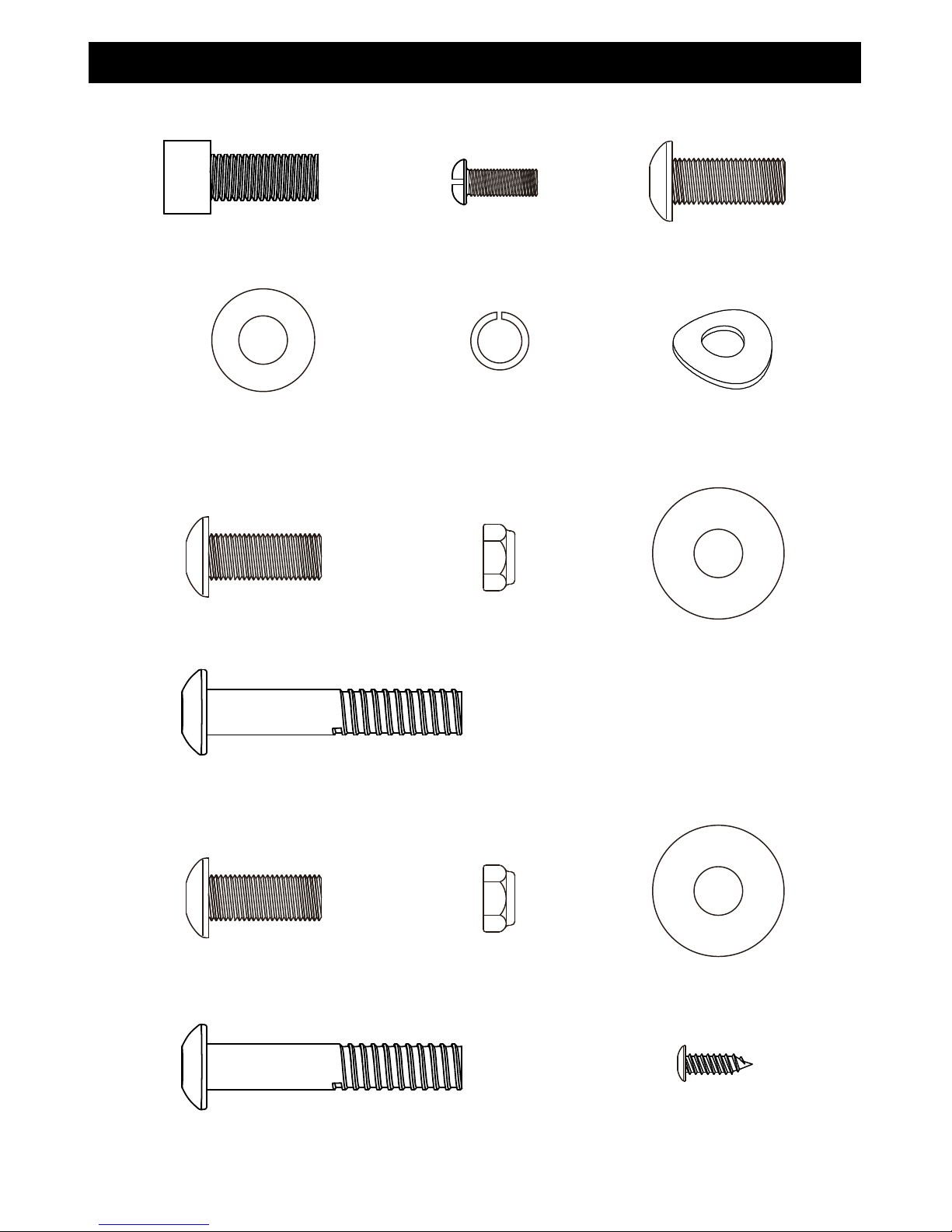
Assembly Pack Check List
STEP
2.
STEP
3.
STEP 1.
#44- 5/16” Flat
Washer (8pcs)
#45- 5/16" Curved
Washer (1pc)
#102- 5/16" × 3/4" Socket
Head Cap Bolt (9 pcs)
#53- M5 × 12 mm Phillips
Head Screw (4pcs)
#46- 5/16" ×1.5T
Split Washer (9pcs)
#43- 5/16" × 3/4" Button
Head Socket Bolt (1pc)
#100- 8.5x23x1.5T
Flat Washer (1pc)
#55- 5/16" Nyloc
Nut (2pcs)
#56- 5/16" ×1-3/4" Button
Head Socket Bolt (2pcs)
#43- 5/16" × 3/4" Button
Head Socket Bolt (1pc)
#55- 5/16" Nyloc
Nut (2pcs)
#56- 5/16" ×1-3/4" Button
Head Socket Bolt (2pcs)
#52- 5 × 12mm Sheet
Metal Screw (4pcs)
#100- 8.5x23x1.5T
Flat Washer (1pc)
#43- 5/16" × 3/4" Button
Head Socket Bolt (4pcs)
3
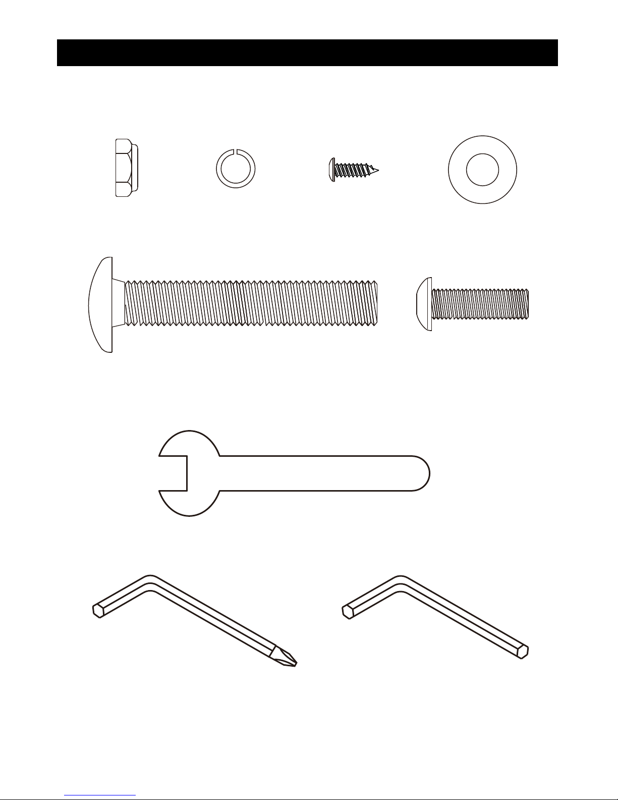
Assembly Pack Check List
STEP
4.
#68- Combination M5 Allen Wrench &
Phillips Head Screw Driver (2pcs)
#69- 19m/m Wrench (1pc)
# 98- 5/16" × 1"
Button Head Socket Bolt
(2pcs)
#44- 5/16” Flat
Washer (2pcs)
#30- 1/2" Nyloc
Nut (2pcs)
#29- 1/2" × 70mm
Carriage Bolt (2pcs)
#52- 5 × 12mm
Sheet Metal Screw
(2pcs)
#46- 5/16" Split
Washer (2pcs)
#103- 6 mm Allen Wrench (1pcs)

4
STEP 1:
1. Locate the Console Mast (9) and slide on Console Mast Cover (82) Make sure the
cover is facing the correct direction, as shown below, before sliding onto mast. Install
the wiring harness (94) into the bottom of the mast and out the top. Be careful when
installing the console mast to the mainframe so as not to pinch or cut the wiring
harness; damage to the console may occur.
2.
Install the console mast on the mainframe using the 6mm Allen Wrench (103) to
tighten 5pcs of 5/16” Socket Head Cap Bolts (102) , 4pcs of 5/16” Flat Washers (44) ,
5pcs of 5/16" Split Washers (46) and 1pcs of 5/16" Curved Washer (45).
Snap the
Console Mast Cover (82) in place on the body of the bike.
3. Route the hand pulse wires (96) from the stationary handle bars (10, 11) through
Console Mast (9) as shown below. Use M5 Allen Wrench (68) to tighten 4pcs of 5/16”
Button Head Socket Bolts (43) to secure both handles on the Console Mast (9).
4. Connect the cables (94 & 96) to the Console (58) and install console onto the Mast (9)
with 4pcs of M5 × 12L Phillips head screws (53) by using the Phillips Head Screw
Driver (68).
5. Secure Front Stabilizer (12) and Rear Stabilizer (13) with 4pcs of 5/16” Socket Head
Cap Bolts (102), 4pcs of 5/16" Split Washers (46) and 4pcs of 5/16” Flat Washers (44)
by using 6mm Allen Wrench (103).
Assembly Instructions

5
6
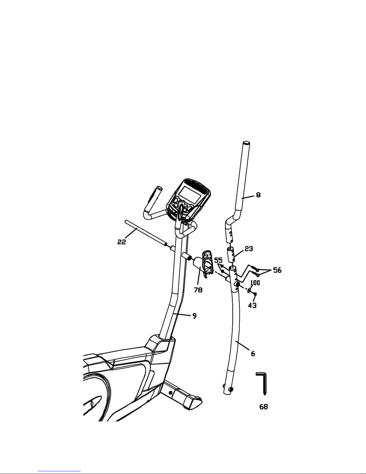
STEP 2:
1. Locate the Right Swing Arm (Upper) (8) and install it through the Swing Arm Bushing
(23) and secure to the Lower swing arm (6). Use M5 Allen Wrench (68) to tighten 2pcs
of 5/16” Button Head Socket Bolts (56) and 2pcs of 5/16" Nyloc Nuts (55) to the swing
arm assembly.
2. Locate the Swing Arm Axle (22) and slide it through the console mast bushings, then
through the Handle Bar Cover (78) and Lower swing arm (6). Use the M5 Allen Wrench
(68) to tighten the 5/16” Button Head Socket Bolt (43) and 8.5mm x 23 Flat Washer
(100) to secure to the Swing Arm Axle (22).
7
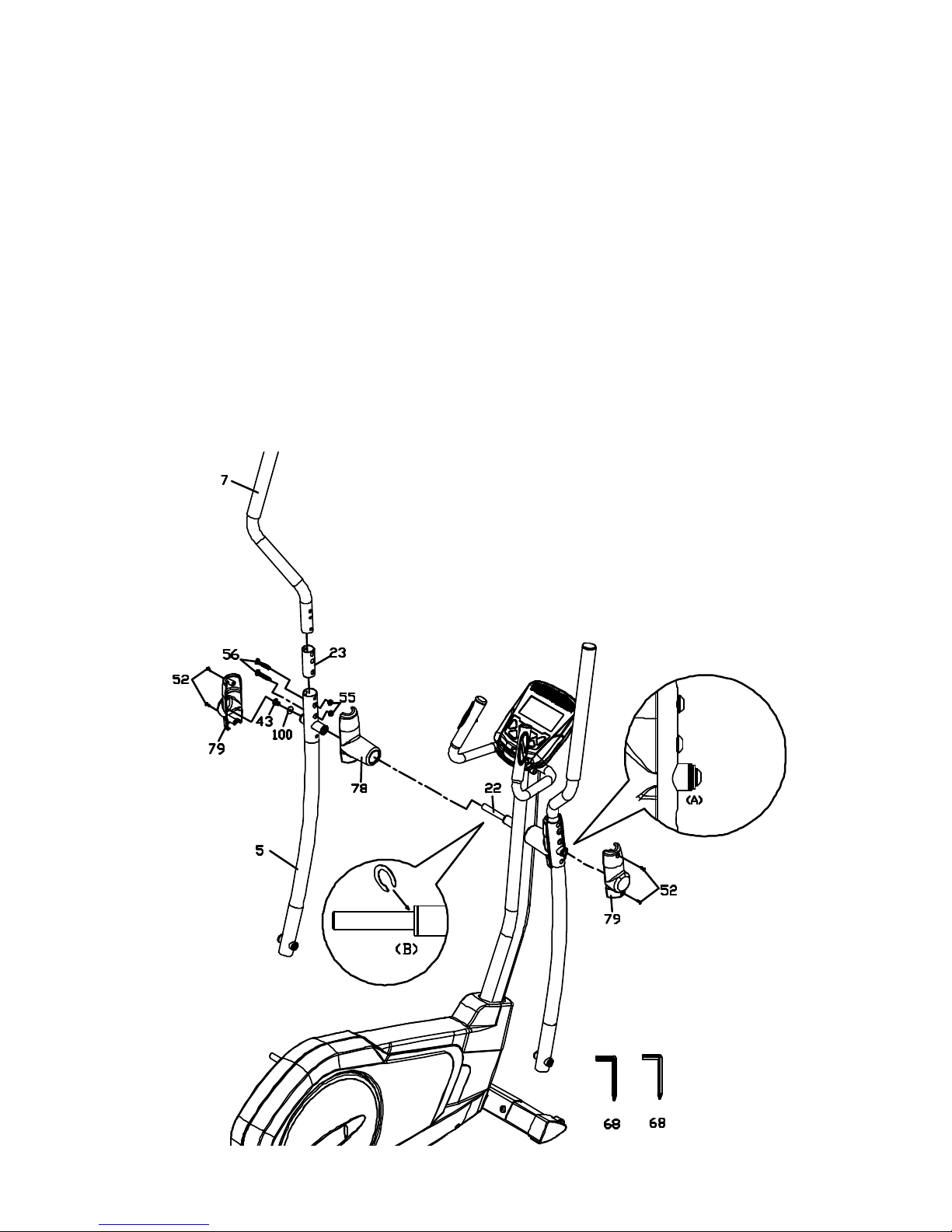
STEP 3:
1. Locate the Left Swing Arm (Upper) (7) and install it through the Swing Arm Bushing
(23) and secure to the Lower swing arm (5). Use M5 Allen Wrench (68) to tighten 2pcs
of 5/16” Button Head Socket Bolts (56) and 2pcs of 5/16" Nyloc Nuts (55) to the swing
arm assembly.
2. Locate the Inner Handle Bar Cover (78) and install on the Lower swing arm and slide
the swing arm with cover onto the axle (22). Secure the swing arm to the axle using
the M5 Allen Wrench (68) to tighten the 5/16” Button Head Socket Bolt (43) and
8.5mm x23 Flat Washer (100) on the Swing Arm Axle (22).
3. If there is seam at area A, please install C-ring at area B. Use Combination M5 Allen
Wrench & Phillips Head Screw Driver (68) to unscrew and release 5/16" × 3/4" Button
Head Socket Bolt (43) and 8.5 × 23 × 1.5T Flat Washer(100) and take apart left Lower
Handle Bar (5) together with Handle Bar Cover-A (78) to install plastic C-ring at area B,
then follow step 2 to install Handle Bar Cover-A(78) and left Lower Handle Bar (5).
Finally, install two Handle Bar Covers-B (79) and use Combination M5 Allen Wrench &
Phillips Head Screw Driver (68) to tighten 5 × 12mm Sheet Metal Screws (52).
 Loading...