

Page 1
INSTALLER:
Leave this manual with the appliance.
CONSUMER:
Retain this manual for future reference.
WARNING: If the information in these
instructions are not followed exactly, a fire
or explosion may result causing property
damage, personal injury or loss of life.
FOR YOUR SAFETY
Installation and service must be
performed by a qualified installer, service
agency or the gas supplier
WHAT TO DO IF YOU SMELL GAS
• Do not try to light any appliance.
• Do not touch any electrical Switch.
• Do not use any phone in your building.
• Immediately call your gas supplier
• from a neighbour’s phone. Follow the
gas supplier’s instructions.
• If you cannot reach your gas supplier
call the fire department.
SERIAL #
ESPRIT
INSTALLATION AND
OPERATING INSTRUCTIONS
Do not store or use petrol or other
flammable vapours and liquids in the
vicinity of this or any other appliance.
This appliance is suitable for installation in a
bedroom or bed sitting room.
This appliance is only for use with the type
of gas indicated on the rating plate. This
appliance is not convertible for use with
other gases unless a certified kit is used.
This appliance is certified for
use in Australia with Natural
Gas and Liquid Propane Gas.
Gas Safety
Cered
AS/NZS 5263.1.3
SAI-400322
This appliance is certified
for use in New Zealand with
Natural Gas only.
MODEL: ESPR.BODYB
SERIES: B
ESPRIT ZERO CLEARANCE
BALANCED FLUE
FIREPLACE
ESPRIT 250418-56
100000393-50
Page 2

Table of Contents
Caution ................................................................... 3
Safety ......................................................................4
Warnings and Cautions ...........................................5
First Fire ...................................................................7
Operating Instructions ............................................. 7
Remote Control Operation ..................................... 8
System Description .............................................. 8
Transmitter (Remote Control with LCD Display) . 8
IFC Module ........................................................... 9
Operating Procedure ............................................ 9
Initializing the System for the rst time ................ 9
Temperature indication Display .......................... 10
Turn on the Fireplace .......................................... 10
Turn off the Fireplace .......................................... 10
Manual Bypass of the Remote System .............. 10
Key Lock............................................................. 10
Remote Flame Control .......................................11
Room Thermostat (Transmitter Operation) .......... 11
Smart Thermostat (Transmitter Operation) ......... 11
Comfort Fan Speed Control ...............................12
Continuous Pilot/Intermittent Pilot
(CPI/IPI) selection ................................................12
Remote dimmer control (Light) ............................12
Key Lock............................................................. 13
Low Battery Power Detection ............................ 13
Transmitter .......................................................... 13
Receiver.............................................................. 13
Note regarding Power Failure ............................. 13
Lighting Instructions ..............................................14
Installing the Esprit ................................................15
Installation Checklist ...........................................15
Esprit Dimensions ................................................ 16
Locating the Fireplace ...........................................17
Non combustible Facing Material Installation ...... 18
Clearances to Combustibles ................................ 19
Minimum Clearance to Combustible Materials .. 19
Mantel Clearances ................................................ 20
Framing and Finishing ........................................... 21
Floor Installation .................................................. 21
Mounting Brackets .............................................. 21
Vent Terminal Minimum Clearances ......................24
Venting Chart .........................................................25
Venting ..........................................................................
.................26
Installing Standoffs ................................................ 26
Maneuver the Esprit into place ............................. 26
Install Venting ....................................................... 26
Gas Connection .....................................................27
Gas connection ..................................................27
Gas Suppy ............................................................ 28
Gas Pressure Check ............................................. 28
Gas Pressure Testing Procedure .......................... 29
Intake Air Damper Installation .............................. 30
Glass Burner Tray Installation ................................31
Rock Set Installation ..............................................34
Log Set Installation ................................................35
Kit Contents.........................................................35
Log set installation ............................................. 36
Door Removal / Installation .................................. 39
Surround Installation Instructions ......................... 40
LED Light Replacement .........................................41
Pilot Assembly Replacement ................................42
Accessing the Gas Injector ...................................44
Blower Fan Replacement ......................................45
Propane Conversion ..............................................47
Maintenance ......................................................... 48
Glass Door ......................................................... 48
Annual Inspection .............................................. 48
Periodically ......................................................... 48
Replacement Parts ............................................... 49
Wiring Diagram ..................................................... 50
Notes ..................................................................... 51
LISTINGS AND CODE APPROVALS
These gas appliances have been tested in accordance with AS/NZS 5263.0:2017 and have
been certified by the Australian Gas Association for installation and operation as described in
these Installation and Operating Instructions. Must be installed as per AS/NZS 5601. Your unit
should be serviced annually by an authorized service person.
AS/NZS 5263.0:2017 contains the requirements and methods of compliance for the “design,
installation and commissioning of gas installations that are associated with the use or
intended use of fuel gases such as natural gas, LP gas or biogas.”
100000393-50
2
250418-56
ESPRIT
Page 3
Caution
FOR YOUR SAFETY - Do not install or operate your Pacic Energy replace without rst reading
and understanding this manual. Any installation or operational deviation from the following
instructions voids the Pacic Energy Warranty and may prove hazardous.
This appliance and its individual shut off valve must be disconnected from gas supply piping system
during any pressure testing of that system at test pressures in excess of 3.5 kPa.
This appliance must be isolated from the gas supply piping system by closing its individual manual
shut off valve during any pressure testing of the gas supply piping system at test pressures equal to
or less than 3.5 kPa.
Do not use the replace if any part has been under water. Immediately call a qualied service
technician to inspect the replace and to replace any part of the control system and any gas control
which has been under water.
This fireplace is equipped with a micro mesh safety screen for your protection and
must be installed with the unit. Removal of the safety screen will cause the fireplace
to become a burn and fire hazard.
ESPRIT
250418-56
3
100000393-50
Page 4

Safety
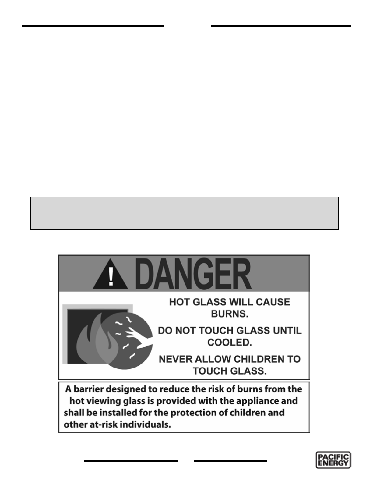
• A barrier designed to reduce the risk of burns from the hot viewing glass is provided with the
Surround Kit component and shall be installed.
• If the barrier becomes damaged, the barrier shall be replaced with the manufacturers barrier
for this appliance.
Any grill, panel or door removed for servicing the unit must be replaced prior to operating.
• It is our policy that no responsibility is assumed by the Company or by any of its employees or
representatives for any damages caused by an inoperable, inadequate, or unsafe condition which
is the result, either directly or indirectly, of any improper operation or installation procedures.
WHAT TO DO IF YOU SMELL GAS
• Do not try to light any appliance.
• Do not touch any electrical Switch.
• Do not use any phone in your building.
• Immediately call your gas supplier from a neighbor’s phone. Follow the gas supplier’s instructions.
• If you cannot reach your gas supplier call the re department.
• Installation and service must be performed by a qualied installer, service agency or the gas
supplier.
100000393-50
4
250418-56
ESPRIT
Page 5

Warnings and Cautions
• DO NOT SPRAY AEROSOLS IN THE VICINITY OF THIS APPLIANCE WHILE IT’S IN
OPERATION.
• DO NOT USE OR STORE FLAMMABLE MATERIALS IN OR NEAR THIS
APPLIANCE.
• DO NOT PLACE ARTICLES ON OR AGAINST THIS APPLIANCE.
• DO NOT MODIFY THIS APPLIANCE.
WARNING
SHOCK HAZARD. CAN CAUSE SEVERE INJURY OR DEATH. THIS DEVICE IS POWERED
BY LINE VOLTAGE. DO NOT TRY TO REPAIR THIS DEVICE. IN NO WAY IS THE
ENCLOSURE TO BE TAMPERED WITH OR OPENED. DISCONNECT FROM LINE VOLTAGE
BEFORE PERFORMING ANY MAINTENANCE.
DUE TO HIGH TEMPERATURES, THIS GAS APPLIANCE SHOULD BE LOCATED OUT OF
TRAFFIC AND AWAY FROM FURNITURE AND DRAPERIES.
CHILDREN AND ADULTS SHOULD BE ALERTED TO THE HAZARDS OF HIGH SURFACE
TEMPERATURES AND SHOULD STAY AWAY TO AVOID BURNS OR CLOTHING IGNITION.
YOUNG CHILDREN SHOULD BE CAREFULLY SUPERVISED WHEN THEY ARE IN THE
SAME ROOM AS THE APPLIANCE. TODDLERS, YOUNG CHILDREN AND OTHERS
MAY BE SUSCEPTIBLE TO ACCIDENTAL CONTACT BURNS. A PHYSICAL BARRIER IS
RECOMMENDED IF THERE ARE AT RISK INDIVIDUALS IN THE HOUSE. TO RESTRICT
ACCESS TO A FIREPLACE OR STOVE, INSTALL AN ADJUSTABLE SAFETY GATE TO
KEEP TODDLERS, YOUNG CHILDREN AND OTHER AT RISK INDIVIDUALS OUT OF THE
ROOM AND AWAY FROM HOT SURFACES.
CLOTHING OR OTHER FLAMMABLE MATERIAL SHOULD NOT BE PLACED ON OR NEAR
THE APPLIANCE.
THE GUARD IS FITTED TO THIS APPLIANCE TO REDUCE THE RISK OF FIRE OR
INJURY FROM BURNS AND NO PART OF IT SHOULD BE PERMANENTLY REMOVED.
FOR PROTECTION OF YOUNG CHILDREN OR THE INFIRM, A SECONDARY GUARD IS
DO NO INSTALL IN A FIREPLACE.
ESPRIT
250418-56
5
100000393-50
Page 6

WARNING
FIRE HAZARD. CAN CAUSE SEVERE INJURY OR DEATH. THE RECEIVER CAUSES
IGNITION OF THE APPLIANCE. THE APPLIANCE CAN TURN ON SUDDENLY. KEEP
AWAY FROM THE APPLIANCE BURNER WHEN OPERATING THE REMOTE SYSTEM OR
ACTIVATING MANUAL BYPASS OF THE REMOTE SYSTEM.
INSTALLATION AND REPAIR SHOULD BE DONE BY A QUALIFIED SERVICE PERSON.
THE APPLIANCE SHOULD BE INSPECTED BEFORE USE AND AT LEAST ANNUALLY
BY A PROFESSIONAL SERVICE PERSON. MORE FREQUENT CLEANING MAY BE
REQUIRED DUE TO EXCESSIVE LINT FROM CARPETING, BEDDING MATERIAL, ETC. IT
IS IMPERATIVE THAT CONTROL COMPARTMENTS, BURNERS AND CIRCULATING AIR
PASSAGEWAYS OF THE APPLIANCE BE KEPT CLEAN.
THIS APPLIANCE MUST NOT BE CONNECTED TO A CHIMNEY FLUE SERVING A
SEPARATE SOLID FUEL BURNING APPLIANCE.
WARNING: FAILURE TO INSTALL THIS APPLIANCE CORRECTLY WILL VOID YOUR
WARRANTY AND MAY CAUSE A SERIOUS HOUSE FIRE.
Congratulations on your purchase of a Pacific Energy Gas Appliance.
Your replace has been professionally installed by:
Dealer name: ___________________________________________________
Phone Number:___________________________________________________
If you discover any problems with your gas appliance contact your dealer immediately to have the
unit repaired.
Caution: Do not attempt to repair the replace because you may cause injury to yourself or others,
and risk causing damage to the unit.
Before operating your appliance carefully read this manual and pay close attention to all Safety
Warnings.
The manual contains important information on the unit’s safe operation and maintenance.
100000393-50
6
250418-56
ESPRIT
Page 7

First Fire
When lit for the rst time, the replace will emit a slight odour for a couple of hours. This is due
to the curing of paints, sealants, gaskets, and lubricants used in the manufacturing process. This
condition is temporary. Open doors and windows to ventilate the area. Odour caused by the
curing process may cause discomfort to some individuals.
It is normal for replaces fabricated from steel to give off some expansion and/or contraction
noises during the start up or cool down cycle. Similar noises are found with your furnace heat
exchanger or cook stove oven.
Operating Instructions
Warning: The home owner must not make any adjustments to the Esprit
other than what can be achieved by using the remote handset (Figure 1) and
the settings control / battery holder located at the bottom of the surround
backing plate (Figure 4). Any other adjustments must be performed by a
qualified service technician.
Before operating this appliance, proceed through the following checklist.
1. Read and understand these instructions before operating this appliance.
2. Check to see that all wiring is correct and enclosed to prevent possible shock.
3. Check to ensure that there are no gas leaks.
4. Make sure that the glass door is in place. Never operate the appliance with the glass door
removed.
5. Verify that all ueing and the termination cap is unobstructed.
6. Verify log placement.
7. When lighting the appliance, the inside of the glass may fog up. This will burn off after a few
minutes of operation.
NOTE: After 3 failed
NOTE: Fireplace may take
attempts to ignite, the
fireplace will enter a 1
minute hibernation period
before attempting to ignite
again.
ESPRIT
250418-56
up to 30 seconds to ignite
each time the “ON” button
has been selected.
7
100000393-50
Page 8
Remote Control Operation
System Description
The Proame 2 Remote Control System consists of two elements:
1. Proame2 Transmitter.
2. Proame2 Integrated Fireplace Control (IFC) board and a wiring harness to connect the IFC to
the gas valve and stepper motor.
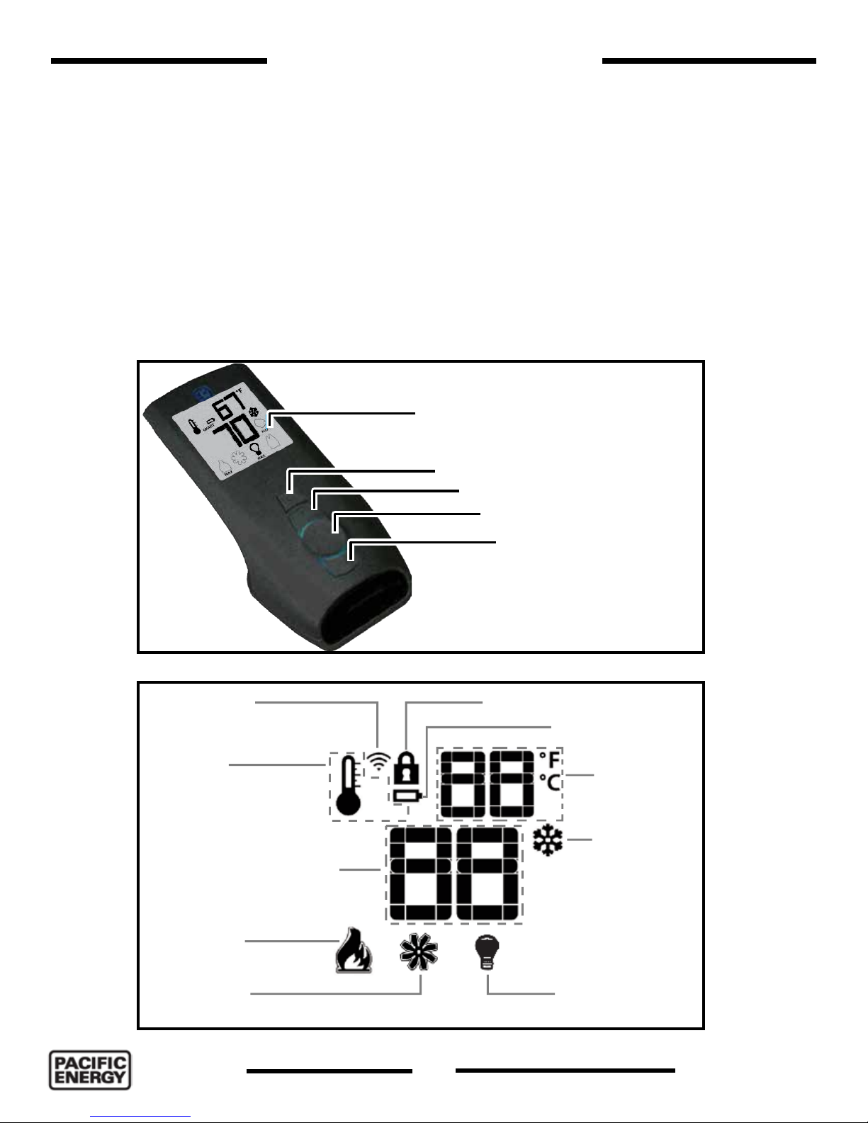
Transmitter (Remote Control with LCD Display)
The Proame 2 Transmitter uses a streamline design with a simple button layout and informative
LCD display Figure 1. The transmitter is powered by 3 AAA type batteries. A Mode key is provided
to Index between the features and a Thermostat key is used to turn on/off or index through
thermostat functions (Figure 1 and Figure 2).
Blue back lit LCD display
ON/OFF Key
THERMOSTAT Key
UP/DOWN Arrow Key
Figure 1: Proame 2 handset.
TRANSMISSION
THERMOSTAT OFF/
ON/SMART
SET POINT:
TEMPERATURE/LEVEL/STATE
FLAME LEVEL
OFF
ON
SMART
MODE Key
KEY LOCK
LOW BATTERY ALARM
ROOM
TEMPERATURE
CPI MODE
COMFORT FAN DIMMER
Figure 2: Proame 2 LCD display.
100000393-50
MAX
8
250418-56
ESPRIT
Page 9
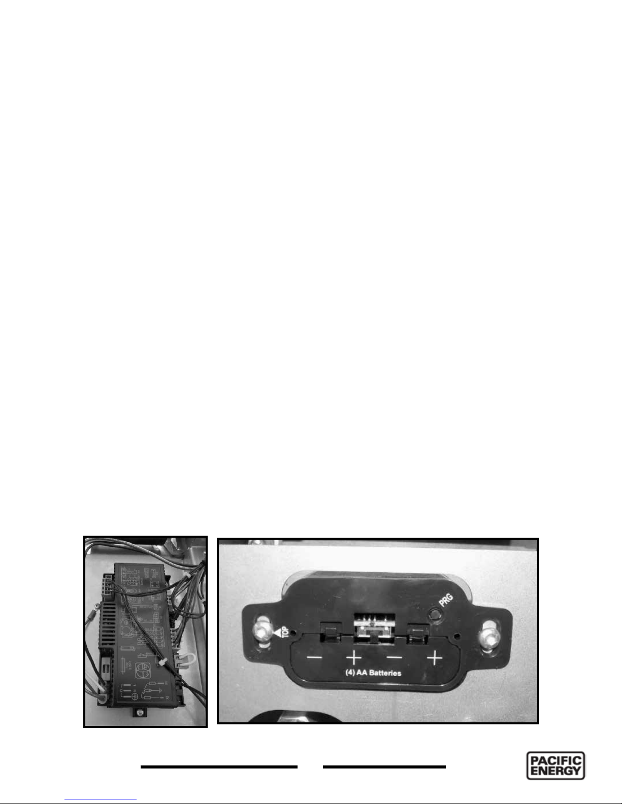
IFC Module
The Proflame 2 Integrated Fireplace Control (IFC) module (Figure 3) is a device that allows automatic
ignition and pilot flame supervision, and commands the functions of the hearth Fireplace. It’s
configured to control the ON/OFF main burner operation, giving the choice of both IPI (intermittent
pilot ignition), and CPI (continuous pilot ignition) modes. The Proflame2 IFC module controls and
connects directly to the pilot assembly and the automatic valve using low electric power.
The IFC module can be powered by both an AC power supply, and battery pack for back up. The
Proflame 2 offers the added ability to control the comfort fan speed from OFF through six (6)
speeds. The external batteries can provide DC power to the IFC allowing the batteries to be used
only when line power is interrupted or lost.
Operating Procedure
Initializing the System for the first time
1. Remove the Front panel if not already removed. Remove the battery cover and install 4 AA
batteries into the battery holder (Figure 4). Install the ON/OFF switch cover over top of the battery
holder. Make sure that the selection switch is on the “Remote” (middle) setting.
2. Install 3 AAA batteries into the Proame2 Remote Transmitter (Figure 1).
3. Energize the electrical power to the replace and open the gas supply line.
4. Insert a straightened paper clip into the opening marked “PRG” of the ON/OFF battery holder
cover (Figure 4) and press the program button once. The module will beep 3 times indicating that
it is ready to synchronize with a remote transmitter.
5. On the remote transmitter, push the power on button once. The remote transmitter will beep
4 times to indicate that the remote transmitter and the control module are now synchronized.
The remote transmitter is now ready to use.
Figure 3: IFC module.
ESPRIT
250418-56
Figure 4: Battery holder - manual controls.
9
100000393-50
Page 10
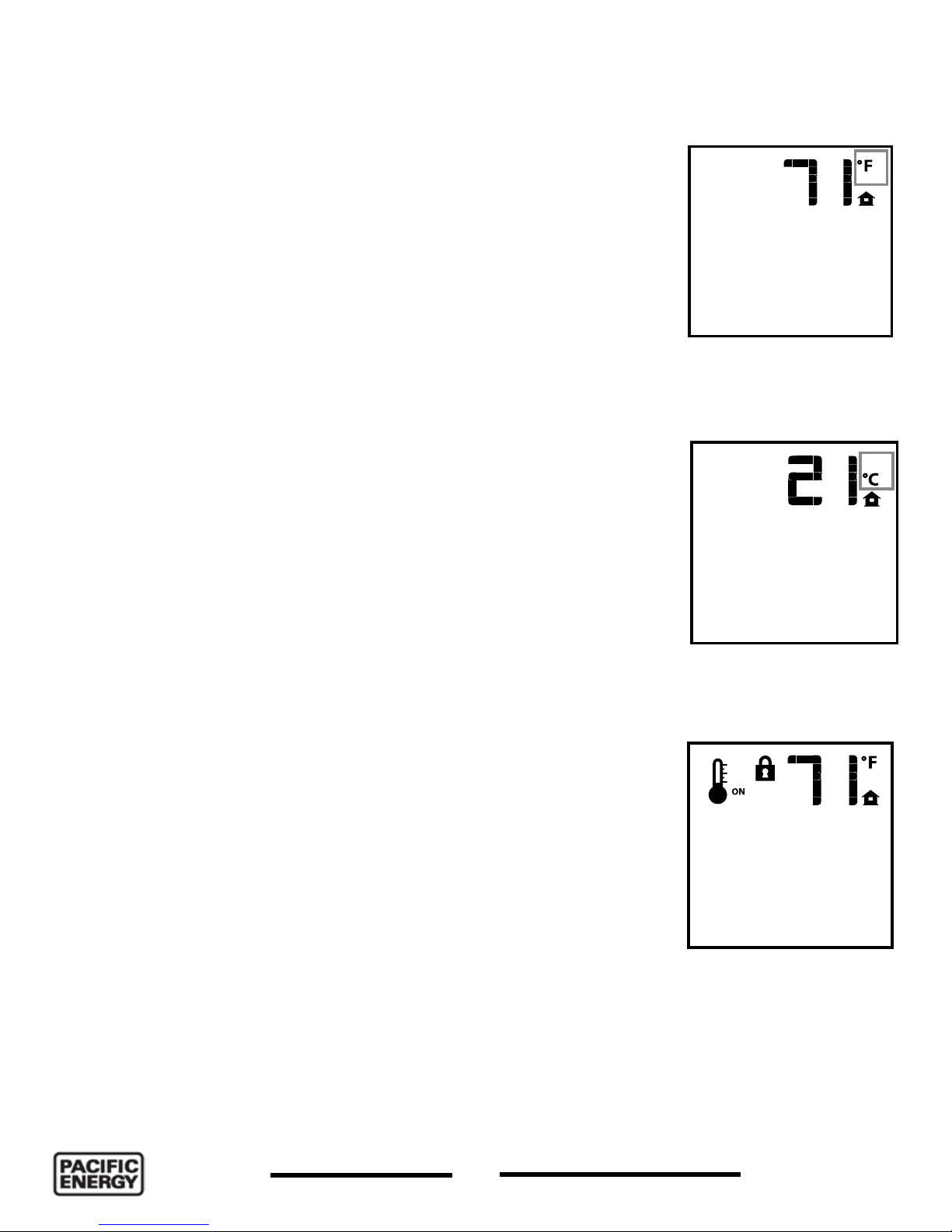
Temperature indication Display
With the system in the “OFF” position, press the Thermostat Key
and the Mode Key at the same time. Look at the LCD screen on the
transmitter to verify that a C or F is visible to the right of the Room
Temperature display (Figure 5 or Figure 6).
Turn on the Fireplace
With the system OFF, press the ON/OFF Key on the remote
transmitter. The remote transmitter display will show some other
active Icons on the screen. At the same time the Receiver will
activate the Heater. A single “beep” from the Receiver (module) will
conrm reception of the command.
Turn off the Fireplace
With the system ON, press the ON/OFF Key on the Remote
transmitter. The Remote transmitter LCD display will only show
the room temperature (Figure 5 or Figure 6). At the same time the
Receiver (module) will turn off the Heater. A single “beep” from the
Receiver conrms reception of the command.
Manual Bypass of the Remote System
If the batteries of the receiver or remote transmitter are low
or depleted, the Heater can be turned off manually using ON/
OFF switch located on battery box. This will bypass the remote
transmitter.
Key Lock
Figure 5: Display in Fahrenheit.
Figure 6: Display in Celsius.
This function will lock the keys to avoid unsupervised operation.
To activate this function, press the MODE and UP keys at the
same time. The lock icon will appear (Figure 7). To de-activate this
function, press the MODE and UP keys at the same time.
100000393-50
10
Figure 7: Key lock.
250418-56
ESPRIT
Page 11
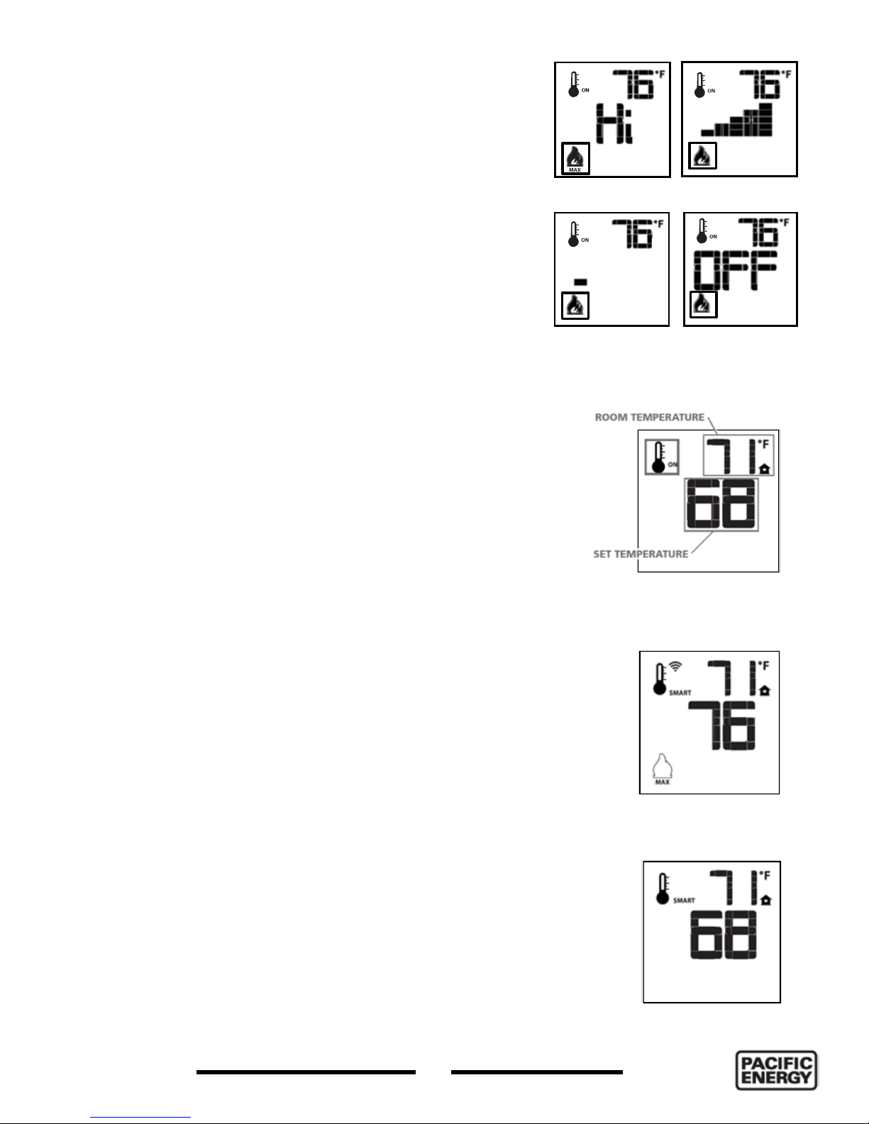
Remote Flame Control
The Proame 2 has six (6) ame levels. With the system turned
on, and the ame level at maximum in the Fireplace, press
the down arrow key once to reduce the ame height by one
step until the ame is turned off.
The up arrow key will increase the ame height each time it
is pressed. If the up arrow key is pressed while the system
is on but the ame is off, the ame will come on in the high
position (Figure 8). A single “beep” will conrm reception of
the command.
Flame level Max
Flame level 5
Room Thermostat (Transmitter Operation)
The remote control can operate as a room thermostat. The
thermostat can be set to a desired temperature to control the
comfort level in a room.
To activate this function, press the thermostat key (Figure 1).
The LCD display on the remote transmitter will change to show
that the room thermostat is “ON” and the set temperature is
now displayed (Figure 9). To adjust the set point, press the up
or down arrow keys until the desired set point temperature is
displayed on the LCD screen of the remote transmitter.
Smart Thermostat (Transmitter Operation)
The Smart Thermostat function adjusts the ame height in
accordance to the difference between the set point and the
room temperatures. As the room temperature gets closer
to the set point, the Smart Function will modulate the ame
down. If the room temperature is cool the Smart function will
modulate the ame up.
To activate this function, press the THERMOSTAT key
(Figure 1) until the word “SMART” appears to the right of the
temperature bulb graphic (Figure 10). To adjust the set point,
press the up or down arrow keys until the desired set point
temperature is displayed on the LCD screen of the remote
transmitter (Figure 11).
Flame level 1
Figure 8: Flame level control.
Figure 9:
Room temperature
control.
Figure 10: Smart ame
control.
Flame Off
ESPRIT
250418-56
11
Figure 11: Smart
ame function set low.
100000393-50
Page 12
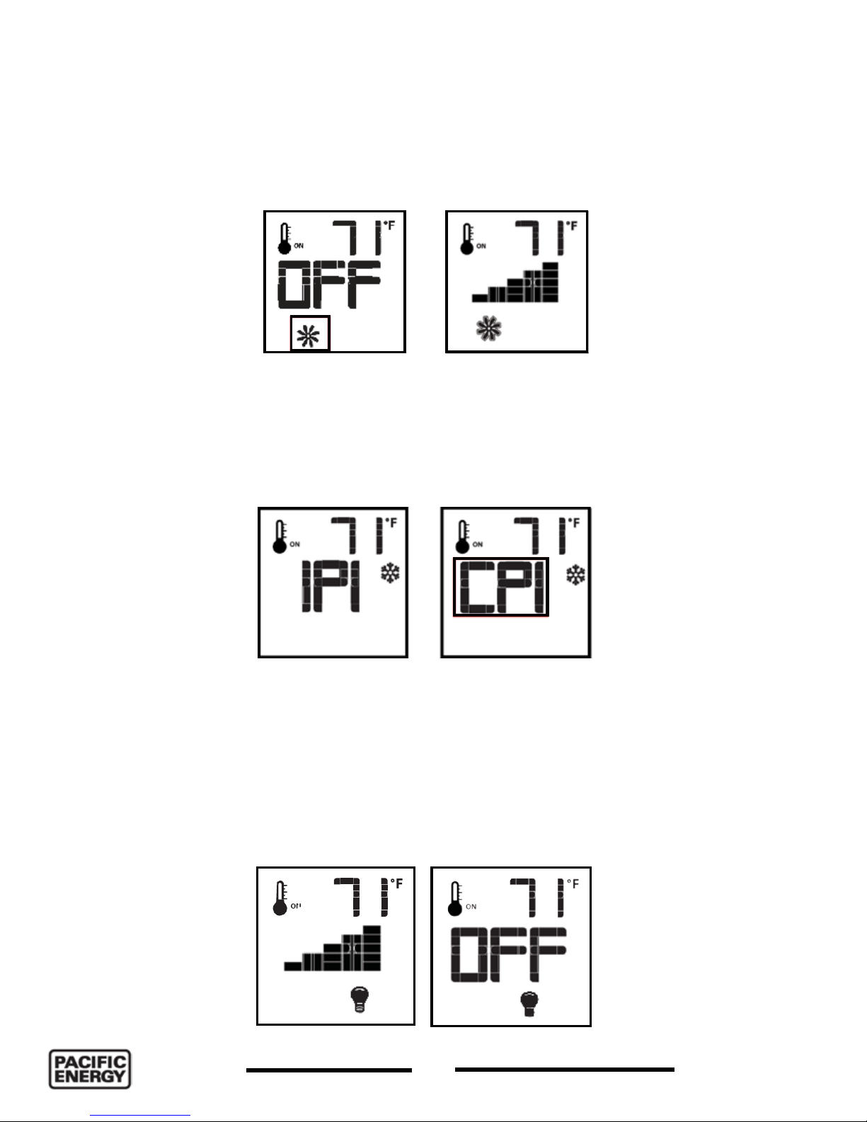
Comfort Fan Speed Control
If the replace is equipped with a hot air circulating fan, the speed of the fan can be controlled by
the Proame system. The fan speed can be adjusted through six (6) speeds. To activate this function
use the Mode Key (Figure 1) to index to the fan control icon (Figure 12). Use the Up/Down Arrow
Keys to turn on, off or adjust the fan speed. A single “beep” will conrm reception of the command.
Figure 12: Comfort fan control.
Continuous Pilot/Intermittent Pilot (CPI/IPI) selection
With the system in “OFF” position press the Mode Key (Figure 1) to index to the CPI mode icon
(Figure 13). Pressing the Up Arrow Key will activate the Continuous Pilot Ignition mode (CPI).
Pressing the Down Arrow Key will return to IPI. A single “beep” will conrm the reception of the
command.
Figure 13: IPI CPI Selection.
Remote dimmer control (Light)
The auxiliary function controls the AUX power outlet by the dimmable light control. To activate this
function use the Mode Key (Figure 1) to index to the light bulb icon (Figure 14). The intensity of
the output can be adjusted through six (6) levels. Use the Up/Down Arrow Keys adjust the output
level. A single “beep” will conrm reception of the command.
Figure 14: Dimmer light control.
100000393-50
12
250418-56
ESPRIT
Page 13

Key Lock
This function will lock the keys to avoid unsupervised operation. To activate
this function, press the MODE and UP keys at the same time (Figure 1).
The lock icon will appear (Figure 15). To de-activate this function, press the
MODE and UP key at the same time.
Low Battery Power Detection
Transmitter
The life span of the remote control batteries depends on various factors:
quality of the batteries used, the number of ignitions of the appliance,
the number of changes to the room thermostat set point, etc. When
the Transmitter batteries are low, a Battery Icon will appear on the LCD
display of the Transmitter (Figure 16) before all battery power is lost.
When the batteries are replaced this Icon will disappear.
Receiver
The life span of the IFC batteries depends on various factors: quality of the
batteries used, the number of ignitions of the appliance and the number of
changes to the room thermostat set point, etc. When the IFC batteries are
low, a “double-beep” will be emitted from the IFC board when it receives a
command from the transmitter. This is an alert for a low battery condition for
the IFC board. When the batteries are replaced the “beep” will be emitted
from the IFC board when a key is pressed. See “Initializing the System for
the rst time” on page 9.
Figure 15: Lock icon.
Figure 16: Low battery
icon.
Note regarding Power Failure
This replace has a battery backup in case of a power outage. In the event of a power outage, the
Esprit will continue to operate for as long as the batteries last, usually up to a couple of weeks. The
batteries will not operate the blower fan or the lights while the power outage lasts. A tip for helping
the batteries to last longer is to not continually adjust the hight of the ame as the valve motor will
be activated each time a new ame level is selected and thus draw power from the batteries.
ESPRIT
250418-56
13
100000393-50
Page 14
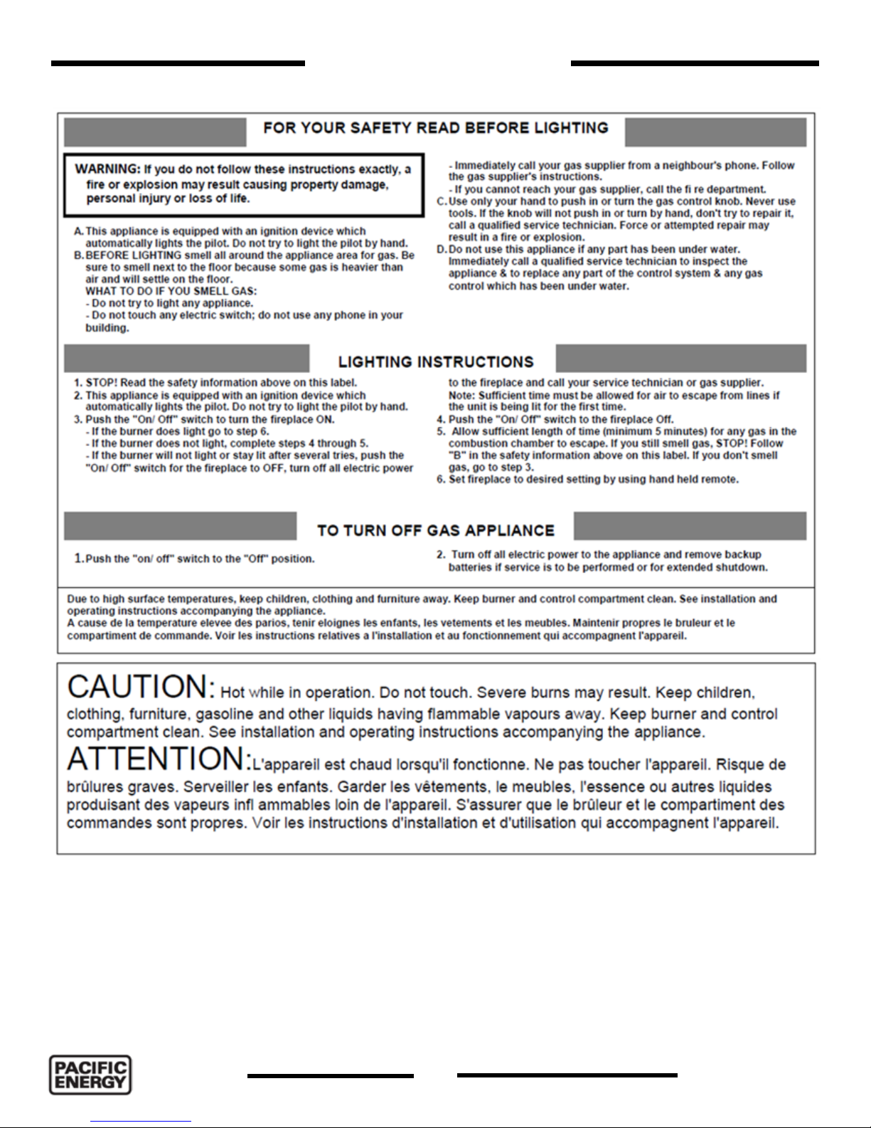
Lighting Instructions
100000393-50
14
250418-56
ESPRIT
Page 15

Installing the Esprit
Installation Checklist
1. Uncrate the Esprit. Examine for shipping damage and that the shipping list is complete.
2. Review the following:
• Esprit dimensions (page 16).
• “Locating the Fireplace” (page 17).
• “Clearances to combustibles” (page 19).
• Mantel clearance (page 20).
• Framing and nishing requirements (page 21).
• Vent Terminal Minimum Clearances (page 24).
• Venting chart (page 25).
3. Maneuver the Esprit into place (page 26).
4. Install venting (page 26).
5. Make gas connections (page 27).
6. Plug electrical connection into receptacle.
7. Gas pressure check (page 28).
8. Gas pressure testing procedure (page 29).
9. Complete nishing. See “Non combustible Facing Material Installation” on page 18
10. Panel set installation (page 31).
11. Vent Damper installation (page 30).
12. Glass or log set installation (page 31 and page 35).
13. Door installation (page 39).
14. Install surround and front covers (page 40).
15. Install backup batteries and link the hand transmitter to the Esprit (page 9).
16. Final check
Before leaving this unit with the customer, the installer must ensure that the appliance is ring
correctly and operation fully explained to the customer.
This includes:
• If required, adjusting the primary air to ensure that the ame does not carbon. First allow the unit
to burn for 15 - 20 minutes to stabilize.
• Installing the Vent Dampers if ame is too hectic.
Caution: Any alteration to the product that causes sooting or carboning that results in damage is not
the responsibility of the manufacturer.
ESPRIT
250418-56
15
100000393-50
Page 16
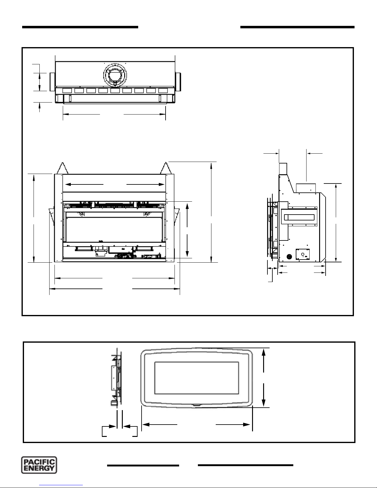
304mm
172mm
Esprit Dimensions
876mm
Top view
230mm
876mm
742mm
Figure 17: Esprit dimensions.
842mm
485.5mm
398mm
1020mm
1108mm
Front view Side view
Contemporary Surround
Adjustable
55 - 70mm
572 mm
415mm
666mm
41 mm
Figure 18: Surround dimensions.
100000393-50
1073 mm
16
250418-56
ESPRIT
Page 17

Locating the Fireplace
In planning the installation for the replace, it is necessary to determine where the unit is to
be installed, location of vent system and where gas supply piping may be plumbed. Various
installations are possible, such as, into an existing wall, a corner, a built in wall or a wall projection.
Due to high temperatures, do not locate this replace in areas of high trafc or near furniture or
draperies. For places where a second side wall is specied, replace should be accessible for
service
Figure 19: Common installation options.
ESPRIT
250418-56
17
100000393-50
Page 18

Non combustible Facing Material Installation
Important Note:
Prior to installation of non-combustible materials by others, check and inspect carefully for
any hairline cracks and / or damage to board.
The non-combustible board must be a minimum of 12 mm thick and comply with AS1530-1
and AS1530-3.
Material which is thinner may crack as a result due to the high temperatures this appliance
emits.
1. Use screws for use with non-combustible boards: Secure non-combustible material around unit
and framing.
Important Note: To avoid cracking the board, pre-drill holes prior to securing to
unit or framing.
2. Wipe any debris/dust from the non-combustible material and dry wall.
3. Prior to securing, it is mandatory to prime the facing and edges using a quality primer. This will
ensure proper adhesion of the tape, ller and paint. Failure to follow this procedure will result in
cracked seams.
4. Tape the seams using a mesh type tape.
5. Fill seams as normal. Avoid using ller which shrinks excessively. Filler must be cured as per
manufacturers’ recommendations.
6. Prime wall for a second time for proper adhesion of paint.
7. Paint walls using a high quality paint which will withstand the high temperatures of 200°C being
emitted from this appliance.
Note:
• When applying 12mm minimum non-combustible board to framework, it is advisable to use the
same 12mm minimum non-combustible board on the whole front face of the wall.
• When using a standard fascia, cut out the clean edge trim opening plus a further 10mm border.
• When using a 15mm nishing trim, cut out the clean edge trim opening plus a further 4mm
border.
• When using painted 12mm minimum non-combustible board as nished wall surface, use 15mm
nishing trim.
• When using clean edge trim, do not seal replace to nished wall material.
The above will allow for possible expansion and contraction.
100000393-50
18
250418-56
ESPRIT
Page 19

610mm
Min.
Top of glass
(Reference point)
12mm min. thick non
combustible material in this
zone only
Contemporary
Surround
915 mm
minimum
915 mm
Min.
Floor
Clearances to Combustibles
Figure 20: Minimum distance from top of the glass to top.
Figure 21: Side view clearances.
Front of the appliance is an open side of the combustion chamber covered with the glass.
Minimum Clearance to Combustible Materials
ENCLOSED SIDE WALL 0 mm From side standoffs
ENCLOSED BACK WALL 0 mm
ENCLOSED TOP 0 mm From top standoffs
EXPOSED SIDE WALL 203 mm From edge of glass
EXPOSED CORNER WALL 50 mm
FLUE 2.54 mm
MANTEL 915 mm min. From top edge of glass.
BOTTOM OF UNIT 0 mm
ESPRIT
250418-56
19
100000393-50
Page 20

Mantel Clearances
Combustible
material
305mm
Mantel
915 mm min. from
edge of glass
12mm thick
non-combustible
board
100000393-50
20
250418-56
ESPRIT
Page 21

Framing and Finishing
Installation of the Esprit Fireplace and electrical and gas connections must conform to the
requirements of The joint Australian/New Zealand standards AS/NZS 5601 and to local codes.
Floor Installation
It is permissible to install the Esprit directly on a oor provided it is a solid surface. There is no
requirement for a hearth to be installed in front of the replace.
Mounting Brackets
Four mounting brackets are included with the Esprit. Loosen the screws indicated in Figure 22 and
Figure 23. The mounting brackets will secure the Esprit to the framing.
The Esprit must be installed so that the oor of the replace is elevated a minimum of 29mm from
the room oor. Minimum 12mm thick non-combustible board or material must cover the front of the
Esprit a minimum of 610mm above the glass door. A mantel (or ceiling) must be a minimum of 915
mm above the glass door. A mantel should extend no more than 305mm from the front wall.
Figure 22: Top mounting bracket location.
Loosen these
screws
Loosen these
screws
Figure 23: Bottom mounting bracket location.
Figure 24: Mounting bracket - side view.
ESPRIT
250418-56
Figure 25: Mounting brackets in place.
21
100000393-50
Page 22

842mm
1108mm
Figure 26: Framing dimensions.
1108 mm
610 mm
Minimum
842 mm
12mm min. thick
non-combustible board
Combustible
Figure 27: Framing and nishing dimensions.
100000393-50
22
250418-56
ESPRIT
Page 23

610 mm
Minimum
Combustible
12mm min. thick
non-combustible board
842 mm
915mm min width
non-combustible board
Figure 28: Framing at the corner.
530mm
1385mm
Figure 29: Minimum clearance corner framing.
ESPRIT
250418-56
23
50mm
Minimum clearance
100000393-50
Page 24

Vent Terminal Minimum Clearances
f
c
n
I
openable
window
j
jj
door
h
h
h
T
ee
P
T
g
k
k
d
b
d
M
a
c
g
See note 2
See note 3
T
T = Flue terminal M = Gas meter Shading indicates prohibited
a - Below eaves, balconies or other projections: MIN. CLEARANCE (mm)
Appliances up to 50 MJ/h input ......................................................................................... 300
Appliances over 50 MJ/h input .......................................................................................... 500
b - From the ground or above a balcony .................................................................................... 300
c - From a return wall or external corner .................................................................................... 500
d - From a gas meter (M) ......................................................................................................... 1000
e - From an electricity meter or fuse box (P) .............................................................................. 500
f - From a drain or soil pipe ....................................................................................................... 150
g - Horizontally from any building structure (unless appliance approved
for closer installation) or obstruction facing a terminal .......................................................... 500
h - From any other fl ue terminal, cowl, or combustion air intake ................................................ 500
j - Horizontally from an openable window, door, non-mechanical air
inlet, or any other opening into a building, with the exception of sub-fl oor ventilation:
Appliances up to 150 MJ/h input ....................................................................................... 500
Appliances over 150 MJ/h input ...................................................................................... 1500
k - From a mechanical air inlet, including a spa blower .......................................................... 1500
n - Vertically below an openable window, non-mechanical air
inlet or any other opening into a building, with the exception of .................................. See table
sub-fl oor ventilation ............................................................................................................ below
NOTES: 1. All distances are measured vertically or horizontally along the wall to a point in line with the nearest
part of the terminal.
2. Prohibited area below electricity meter or fuse box extends to ground level.
3. See clause 5.13.6.6 for restrictions on a fl ue terminal under a roofed area.
4. See Appendix J, Figure J1(a) and J2(a) for clearances required from a fl ue terminal to a LP Gas
cylinder. A fl ue terminal is considered to be a source of ignition.
MINIMUM CLEARANCES REQUIRED FOR BALANCED FLUE TERMINALS
OR THE FLUE TERMINALS OF OUTDOOR APPLIANCES
CLEARANCE ‘n’ (mm)
Space Heaters All other appliances
Up to 50 MJ/h input Up to 50 MJ/h input Over 50 MJ/h & up to 150 MJ/h Over 150 MJ/h input
150 500 1000 1500
Figure 3.4
100000393-50
24
250418-56
ESPRIT
Page 25

10980 mm
10675 mm
10370 mm
10065 mm
9760 mm
9455 mm
9150 mm
8845 mm
8540 mm
8235 mm
7930 mm
7625 mm
7320 mm
7015 mm
6710 mm
6405 m m
Venting Chart
No venting options
equaling 90° can be used without reducing horizontal run. For each additional 90° elbow, or an equal combination of elbows, reduce
to the boundaries of this chart. A Maximum of three 90° elbows may be used. Only one (1) 90° elbow or combination of other elbows
horizontal vent run by 610 mm. Ensure vent pipe is properly supported.
guideline for installations. Every venting conguration is different, and the damper setting may need slight adjustment from this chart.
Note: The vent must not exceed a total length of 10675 mm. Any combination of rise and run may be used but must be constrained
Note: The intake damper positions specied in this chart were set in a controlled testing environment, and serve as a general
Install Damper Do Not Install Damper
Exhaust Damper Position To Vertical Run Chart
6100 mm
5795 mm
5490 mm
5185 mm
4880 mm
4575 mm
4270 mm
3965 mm
3660 mm
3355 mm
3050 mm
2745 mm
2440 mm
2135 mm
1830 mm
1525 mm
1220 mm
915 mm
610 mm
305 mm
0
Venting envelope
Venting envelope
No venting options
1830 mm
1525 mm
1220 mm
915 mm
610 mm
305 mm
0’
2135 mm
Do not use an unlined masonry chimney as the flue for this appliance
ESPRIT
250418-56
2440 mm
2745 mm
3050 mm
3355 mm
3660 mm
3965 mm
25
4270 mm
4575 mm
4880 mm
5185 mm
5490 mm
5795 mm
6100 mm
6405 mm
100000393-50
Page 26

Venting
46DVA-HSC
Horizontal
Terminal
This replace is certied for use with 101.6mm x 168.275mm coaxial venting components only. It is
permitted to only use Duravent certied venting for this appliance.
46DVA-VCH
Vertical
Terminal
Standoffs
Figure 30: Standoff.
Figure 31: Standoff on replace top.
This unit comes with two standoffs (Figure 30,31) on the top of the replace.
Maneuver the Esprit into place
The appliance must be installed on a at, solid, continuous surface. For example, a wood, metal or
concrete oor or in a raised (on the wall) application. The appliance must be installed on concrete or
a metal or wood panel extending the full width and depth of the appliance.
Install Venting
This gas replace and venting system must be vented directly to the outside of the building and
never be attached to a chimney serving a separate solid fuel or gas burning appliance. Each direct
vent gas appliance must use its own separate venting system.
100000393-50
26
250418-56
ESPRIT
Page 27

Gas Connection
Open
Shut
Figure 32: Connecting gas line.
Figure 33: Gas ow tap.
Gas connection
To make the required electrical and gas connections, start by positioning the gas replace. Connect
the gas supply line to the 3/8” BSPT tting that located on a shut off valve bracket as seen in
Figure 32. A gas shut off tap is located inside the replace and may be accessed by removing the
surround, screen and front. Please see the gas supply section for requirements of the gas supply.
Servicing of the appliance can be performed from the front of the unit.
Caution: The gas line should be installed by a qualied service person in accordance with all
building codes. This section is intended as a guide for qualied technicians installing this appliance.
Consult local and/or national building codes before proceeding.
• Gas supply line connection is located on the right side of the replace. Gas connection accepts a
3/8” BSPT tting. Correct gas line diameter must be used to assure proper operation and pressure.
• The replace input rating is shown in the chart on page 28.
• A drip leg must be installed in the gas supply line going to the gas control valve to minimize the
possibility of any loose scale or dirt within the gas supply line from entering the control valve.
Check local codes for additional requirements.
Turn on the gas supply and check that all connections are tight and leak free.
ESPRIT
250418-56
27
100000393-50
Page 28

Gas Suppy
Servicing of the appliance can be performed from the front of the unit by removing the door and the gas tray
from the unit.
Caution: The gas line should be installed by a qualied service person in accordance with all building codes.
This section is intended as a guide for qualied technicians installing this appliance. Consult local and/or
national building codes before proceeding.
• Gas supply line connection is located on the side of the replace. Gas connection accepts a ½” NPT
tting. Correct gas line diameter must be used to assure proper operation and pressure.
• The replace input rating is shown in the chart below.
• A drip leg must be installed in the gas supply line going to the gas control valve to minimize the possibility
of any loose scale or dirt within the gas supply line from entering the control valve.
Check local codes for additional requirements.
Turn on the gas supply and check that all connections are tight and leak free.
Gas Pressure Check
Please refer to “Gas Pressure Testing Procedure” on page 29 for gas pressure testing procedure.
Esprit: 240 Vac, 0.72 amp, 0.0751 kW
Gas Type Injector
(mm)
Natural Gas 2.55 21.10 /31.65 0.87 1.13
Propane 1.52 21.10 / 27.43 2.48 2.75
Min / Max
(MJ/hr)
Manifold Pressure
(kPa)
Inlet Pressure
(kPa)
100000393-50
28
250418-56
ESPRIT
Page 29

Gas Pressure Testing Procedure
Note: To test the gas pressure, turn off the gas supply to the appliance before loosening test
point screws.
Verify gas pressures with the fireplace lit and at the highest setting.
1. Remove window surround and locate the valve.
2. Locate the inlet and outlet test ports on the valve which can be seen in Figure 34. After locating
test ports loosen the screws within the ports using a at-tip screwdriver.
3. Attach pressure gauge to the test ports
4. Turn gas supply back on and test pressures.
5. After testing is nished turn off gas supply, remove the pressure gauges and tighten up the
screws in the test points.
PILOT ADJUSTMENT
SCREW
PRESSURE
MODULATOR
DEVICE
MAIN GAS
SOLENOID
MANIFOLD PRESSURE
TEST POINT
PILOT
SOLENOID
INLET
PRESSURE
TEST POINT
Figure 34: Gas control valve.
ESPRIT
250418-56
29
100000393-50
Page 30

Damper
Damper
Intake Air Damper Installation
The Esprit replaces come with the damper that can limit the ow of intake air. This damper is
located behind the air bafe at the top of the rebox. Sometimes on installations that involve vertical
venting congurations over 701 cm in height, the intake air tends to accelerate down the vent
causing hectic ame action. This damper has to be closed to reduce the speed of the intake air
and thus calm the ames for a more natural look. See (page 25) to check if damper required for
installation.
Figure 35: Air damper location.
100000393-50
Figure 36: Damper detail.
30
250418-56
ESPRIT
Page 31

Glass Burner Tray Installation
Figure 37: Glass burner tray.
Installation
1. Insert the glass burner tray (Figure 38) into the rebox. Take note of the cut out for the pilot
assembly and orient the tray so that the air ow ports are facing up. The edges of these ports will
prevent the glass media from falling down into the rebox. Secure the tray to the ledges on all
four sides of the rebox with the supplied screws (Figure 39).
Figure 38: Inserting glass media tray.
ESPRIT
250418-56
Figure 39: Securing glass media tray to rebox oor.
31
100000393-50
Page 32

2. Insert the burner into the glass media tray and secure with 6 supplied screws (Figure 40 and
Figure 41).
3. Once the burner is seated and secured, adjust the venturi air shutter, located under the rebox
oor, as follows: for natural gas, keep the setting on the right side of the adjustment slot (Figure
42). For propane gas, keep the setting on the left side of the slot (Figure 43). Further venturi
adjustment can be easily made later once the Esprit is lit.
4. Place the pilot shield over the pilot assembly and into the cut out of the glass media tray (Figure
45). Be sure to push the shield down far enough so that the pilot ame is able to reach the burner
without being impeded by the shield wall itself.
Figure 40: Insertion of burner. Figure 41: Securing burner to burner tray.
Figure 42: Initial venturi setting for natural gas. Figure 43: Initial venturi setting for propane gas.
100000393-50
32
250418-56
ESPRIT
Page 33

5. Spread glass media evenly over the surface of the burner tray. Use as much glass media as is
needed to fully cover the burner tray but not so much that the glass media spills over into the air
ow ports (Figure 46).
Figure 44: Pilot assembly shield. Figure 45: Pilot assembly shield installed.
Figure 46: Glass media installation.
ESPRIT
250418-56
33
100000393-50
Page 34

Rock Installation
To install the optional rock set, simply place desired number of rocks into the replace pan as
seen in Figure 48 making sure no rocks are in the ame when the unit is operating.
Figure 47: Glass media.
Figure 48: Rock set installation.
100000393-50
34
250418-56
ESPRIT
Page 35

Kit Contents
Optional Log Set Installation
Log number 1 Log number 2
Log number 4
Log number 6
Figure 49: Esprit log set.
Log number 3
Log number 5
Log numbers 7 & 8
ESPRIT
250418-56
Figure 50: Ember material.
35
100000393-50
Page 36

Log set installation
Figure 51: Ember material spread evenly over burner tray.
1. Spread ember material evenly over the surface of the burner tray. Use as much ember material as
is needed to fully cover the burner tray but not so much that the ember material spills over into
the air ow ports (Figure 51).
Figure 52: Log number 1 position.
1. Place log number one into the left hand corner of the rebox. The back of the log should be up
against the rear panel and positioned in such a way so that it is stable and so that it does not
cover the air vent port (Figure 52).
2. Position log number two so that its left side is supported by log number one and so that the post
on the right side is vertical (Figure 53).
100000393-50
Figure 53: Log number 2 position.
36
250418-56
ESPRIT
Page 37

Figure 54: Log number 3 position. Figure 55: Log number 4 position.
3. Log number three has a hole which is to t over the post in log number two. The right end of this
log is to point toward the right hand side panel (Figure 54).
4. Position log number four so that its thicker end is touching the left side panel (Figure 55). Make
sure that this log is forward enough so that none of the air vent ports behind it are being blocked.
5. Log number ve is to be positioned as shown in Figure 56 . As with log number four, make sure
that this log is forward enough so that the air vent ports located behind it are not blocked.
6. Place log number six so that its pointed end rests on top of log number four while its other end
extends back towards log number two (Figure 57). Be sure that this log does not cover any of the
air vent ports.
7. Logs number seven and eight are identical. Place one at either end of the rebox as desired
(Figure 58 and Figure 59).
Figure 56: Log number 5 position.
ESPRIT
250418-56
Figure 57: Log number 6 position.
37
100000393-50
Page 38

Figure 58: Log number 7 position.
Figure 59: Log number 8 position.
Figure 60: Completed log placement.
100000393-50
38
250418-56
ESPRIT
Page 39

Door levers
Door Removal / Installation
Removal
1. Hold the door. Pull 3 levers to release the door.
2. Lift the door up to release it from the slot on the bottom of the rebox.
Installation
3. Place the door in the slot at the bottom of the rebox opening. Push 3 levers at the top of the
door to secure the door.
Figure 61: Door handles.
ESPRIT
250418-56
39
100000393-50
Page 40

Surround Installation Instructions
Installation
1. Remove front and screen from surround.
2. Position the surround so that the battery pack is at the bottom (Figure 62). Plug the battery pack
connector into the back of the battery pack (Figure 64).
3. Fasten the surround base to the replace using supplied screws and mounting holes located
along the inner edge of the base (Figure 65).
4. Install screen panel in slots on inner side of the surround base (Figure 66).
5. Install the surround front (Figure 67) by positioning it so as to clear the notches and secure by
applying downward pressure in order to engage the locking tabs.
Figure 62: Surround with battery pack. Figure 63: Battery pack and manual controls.
Figure 64: Connecting the battery pack. Figure 65: One of 4 attaching points on the
surround.
Figure 66: Screen panel. Figure 67: Front cover with protective lm.
100000393-50
40
250418-56
ESPRIT
Page 41

LED Light Replacement
The LED lights assembly can be replaced by removing the glass door. It is not necessary to remove
the surround and front and screen but the extra room that will become available once the surround
and front is removed will make accessing the assembly easier (Figure 69).
To Remove:
1. Two screws hold the assembly to the ceiling of the rebox (Figure 68), once the screws are
removed, the shield will separate from the rest of the assembly.
2. Gently pull the assembly down from the ceiling. There will be some resistance when pulling the
assembly because the light assembly is surrounded by insulation. The connector may become
hung up in the insulation while trying to maneuver the assembly out but with a little effort, the
assembly will come out.
3. Disconnect the LED assembly and plug the replacement assembly in to the connector.
4. Gently return the assembly to its place inside the rebox ceiling. Reattach the assembly and the
shield using the previously removed screws.
Figure 68: View of LED light from
inside of the rebox.
LED Lights
Figure 69: LED lights location.
Insulating
gasket
Shield
Figure 70: LED light assembly.
ESPRIT
250418-56
41
100000393-50
Page 42

Pilot Assembly Replacement
1. Remove the front, screen panel and the surround backing. Disconnect the connector from the
battery holder/receiver from the surround backing. This will expose the area beneath the rebox
oor. See “Surround Installation Instructions” on page 40 and follow the directions in reverse
order to remove.
2. Close the electrical supply. Shut the gas valve, see “Figure 33: Gas ow tap.” on page 27.
3. Remove the glass door. See “Door Removal / Installation” on page 39.
4. Remove the log set and ember material or the glass media - whichever is installed.
5. Remove 2 screws that attaches the control module caddy from its bracket (Figure 71). Remove
the control module along with its’ caddy.
6. Rotate the control module and caddy so that the igniter and rectier connectors (X2 & X3) are
able to be disconnected (Figure 72). Disconnect red and black leads.
Figure 71: Remove control module caddy.
X2 (Black)X3 (Red)
Figure 72: Disconnect leads to pilot assembly.
Figure 73: Pilot gas supply line connector.
100000393-50
Figure 74: Releasing pilot gas line from gas valve.
42
250418-56
ESPRIT
Page 43

7. Locate the pilot assembly (Figure 73).
8. Unscrew the pilot gas supply line using a 7/16” (11 or 12 mm) wrench (Figure 74).
9. Remove two screws from holding the Pilot Assembly to the rebox oor (Figure 75).
10. Extract the old pilot assembly and install replacement assembly (Figure 76).
11. When reinstalling the igniter and rectier leads, be sure to refer to
the wiring diagram printed on the control module (Figure 77) before
connecting the leads.
Figure 75: Pilot assembly screws.
X2 (Black)
X3 (Red)
Figure 76: Pilot.
Figure 77: Igniter and rectier wiring.
ESPRIT
250418-56
43
100000393-50
Page 44

Accessing the Gas Injector
To expose the gas injector:
1. Remove the front, screen panel and surround to expose the display media, electronics and gas
components. Be sure to unplug the connector to the back of the battery pack on the surround.
2. If already installed, remove the log set, ember material and burner, or glass media, glass tray and
burner.
3. Locate the venturi adjustment screw under the rebox oor (Figure 94). Loosen it and move it to
the right to allow for access to the injector using a 1/2” (or 13 mm) socket and extension.
4. Using the 1/2” (or 13 mm) socket, remove the injector.
5. Spread a small amount of thread sealant onto the threads of the replacement injector and install
using the 1/2” (or 13 mm) socket (Figure 80).
6. Return the venturi to the desired setting.
Figure 78: Access to injector.
LP
NG
Figure 79: Venturi air shutter adjustment screw.
Figure 80: Inserting replacement injector.
100000393-50
44
250418-56
ESPRIT
Page 45

Blower Fan Replacement
Blower Fan Removal
To access and remove the blower fans, the rebox oor must be removed:
1. Remove the front, screen panel and the surround backing. Disconnect the connector from the
battery holder from the surround backing. This will expose the area beneath the rebox oor. See
“Surround Installation Instructions” on page 40 and follow the directions in reverse order to
remove.
2. Close the electrical supply. Shut the gas valve, see “Figure 33: Gas ow tap.” on page 27.
3. Disconnect the lights wiring leads (Figure 81). This will allow the rebox oor to be completely
removed .
Figure 81: Disconnect leads to lights.
4. Remove the glass door.
5. Remove the log set and ember material or the glass media - whichever is installed.
6. Remove the upper bafe (page 32).
7. Remove the porcelain panels.
8. Remove the rebox oor screws from the perimeter of the rebox oor (Figure 82).
ESPRIT
250418-56
45
100000393-50
Page 46

Figure 82: Firebox oor with panels removed.
Securing nuts
Figure 83: Firebox oor partially removed.
9. Lift the oor part way out of the replace until the electrical connectors for the blower fans can
be accessed (Figure 83). Disconnect the blower wiring leads and completely remove the rebox
oor from the replace.
10. Each blower fan is afxed to the rear wall by two 7/16” nuts. Completely remove the two inside
nuts and loosen the two outside nuts (Figure 84).
11. Remove the blower fan(s).
Figure 84: Blower fans securing nut location. Figure 85: Blower fans released from rear wall.
100000393-50
46
250418-56
ESPRIT
Page 47

Propane Conversion
Before starting the conversion make sure to shut off
the gas supply to the unit and allow fireplace to cool
to room temperature.
To convert the gas replace from natural gas to propane,
a kit is required. This kit comes with new pilot and
burner orices as well as a new pressure modulator for
the valve.
To switch the pressure modulator, follow the instructions
that are provided with the conversion kit. To change the
orices you are required to remove the door, media set,
and burner. Please refer to the appropriate sections of
this manual and follow instructions on how to correctly
remove the components.
After removing the burner you will have access to the
burner orice which is located on the bottom of the
burner tray (Figure 86). The orice can be removed
using a ½ inch socket. Before installing the new orice,
thread sealant needs to be applied to the threads of the
new orice to ensure a proper seal when installed.
Venturi air shutter
Pilot assembly
Figure 86: Pilot, orice and air shutter.
Orice
To replace the pilot orice you will need to remove
the pilot hood which is held in place by a spring. First
remove the spring, and then remove the hood by pulling
it up from the pilot bracket (Figure 87). To remove the
existing orice insert a 4mm Allen wrench into the
hexagonal key-way of the orice and rotate counterclockwise until free. Insert the new orice using the same
Allen wrench and tighten it until a torque of 12.20 Nm (9
lbf) is achieved. Replace the pilot hood by aligning the
tab on the base of the hood with the slot in the side of
the pilot journal, and push the hood down onto the pilot
bracket. Replace the spring by pushing it onto its seat.
Before returning the burner into position, the venturi
shutter will have to be adjusted to the correct opening.
The correct venturi settings are shown in Figure 88.
Loosen the screw and slide the shutter. Tighten the
screw, and return the burner into position. Further
adjustment may be necessary.
Figure 87: Pilot hood removal.
LP
NG
Figure 88: Venturi air shutter adjustment.
ESPRIT
250418-56
47
100000393-50
Page 48

Ignitor
Hood
Maintenance
Turn off gas and electrical power supply (if applicable) and allow ample time for unit to cool before
servicing appliance. It is recommended that the replace and its venting should be inspected at
least once a year by a qualied service person.
Glass Door:
Warning: Do not operate replace with glass door removed, cracked or broken. Replacement of
the glass door should be done by a licensed or qualied service person. Check glass panel gasket,
replace if necessary. It is important that the glass seal be maintained in good condition.
Do not strike or otherwise impact the glass in any way that may cause it to break. If the glass
becomes cracked or broken it must be replaced before using the replace. Replacement door
can be obtained from your nearest Pacic Energy dealer. Do not substitute with any other type. To
remove broken glass, remove Door as noted in “Door Removal” section.
Annual Inspection:
a) Remove glass door and decorative media (such as logs and rocks). Inspect decorative media
and burner assemblies for soot buildup. If excessive buildup of soot is present, have a
qualied service person inspect and adjust unit for proper combustion. Clean burners with a
brush or vacuum cleaner, paying close attention to burner ports.
b) Check the pilot system for proper ame size and operation. Clean pilot free (Figure 89) of soot,
dust or any other deposits.
c) Check that the vent pipe and vent terminal are open and free from blockage or debris. If the
venting is disassembled for cleaning, it must be
properly assembled and re-sealed.
d) Check and replace batteries as needed.
Note: The appliance area must be kept clear and
free from combustible materials, gasoline and other
ammable vapors and liquids.
Periodically:
a) Viewing glass may be cleaned as necessary with
replace glass cleaner.
b) Exterior nish may be cleaned with mild soap and
water.
Figure 89: Esprit pilot assembly.
CAUTION: Do not use abrasive cleaners on glass or any other part of the replace.
Do not clean glass when hot.
100000393-50
48
250418-56
ESPRIT
Page 49

Replacement Parts
ESPRIT LINEAR GAS FIREPLACE SALES CODES
UNIT SKU
ESPRIT LINEAR GAS FIREPLACE ............................................. 12030011
REPLACEMENT PARTS
ESPRIT REPLACEMENT DOOR WITH GLASS .......................... 80000867
ESPRIT REPLACEMENT SCREEN .............................................80000164
COMPLETE REPLACEMENT GAS TRAY ................................... 80002080
REPLACEMENT GAS VALVE ..................................................... 80000194
REPLACEMENT CONTROL MODULE ....................................... 80002043
REPLACEMENT PILOT ASSEMBLY........................................... 80000193
REPLACEMENT REMOTE CONTROL .......................................80002044
REPLACEMENT BLOWER ......................................................... 80002045
BURNER OPTIONS
LOG BURNER SET ..................................................................... 12150007
GLASS BURNER SET ................................................................12150006
GLASS 5LB BLACK ..................................................................12160014
PANEL SETS
PORCELAIN PANEL SET BLACK ............................................... 12200026
SURROUND AND TRIM OPTIONS
CONTEMPORARY BACKING PLATE BLACK ............................12120019
CONTEMPORARY BACKING PLATE GREY. .............................. 12120018
CONTEMPORARY FRONT TRIM PLATE GREY ......................... 12210021
CONTEMPORARY FRONT TRIM PLATE - BLACK .................... 12210023
CONTEMPORARY FRONT TRIM PLATE - STAINLESS .............12210025
STRAIGHT EDGE FRONT TRIP PLATE - BLACK ...................... 12210081
DESIGN OPTIONS
TRANQUILITY ROCK SET .......................................................... 12160017
METRO ROCK SET - BLACK ..................................................... 12160018
METRO ROCK SET - GREY ....................................................... 12160019
PERFORMANCE OPTIONS
LP CONVERSION KIT ................................................................ 12180002
ESPRIT
250418-56
49
100000393-50
Page 50

Wiring Diagram
LED
LED
PILOT
COMFORT
BURNER
LAMP
FAN
(4) AA Batteries
100000393-50
50
Caution: Label all wires
prior to disconnection
when servicing controls.
Wiring errors can
cause improper and
dangerous operation.
Verify proper operation
after servicing.
250418-56
ESPRIT
Page 51

Notes
ESPRIT
250418-56
51
100000393-50
Page 52

© 2018 Copyright Pacic Energy Fireplace Products LTD
Reproduction, adaptation, or translation without prior written permission
is prohibited, except as allowed under the copyright laws.
For technical support, please contact your retailer
Pacific Energy Australia PTY LTD.
Web site: www.pacificenergy.net
120 Victoria Street, North Geelong,
Victoria
 Loading...