

Page 1

ESP-WROOM-5C
U
ser Manual
www.espressif.com
Version 0.1
Espressif Systems
Copyright © 2019
Page 2

This document provides introduction to the specifications of ESP-WROOM-5C hardware.
Release Notes
Date Version Release notes
2019.01 V0.1 For certification only.
Documentation Change Notification
Espressif provides email notifications to keep customers updated on changes to
technical documentation. Please subscribe at https://www.espressif.com/en/subscribe.
Certification
Download certificates for Espressif products from https://www.espressif.com/en/
certificates.
About This Guide
Page 3

Table of Contents
1. Overview 1................................................................................................................................
2. Pin Description 5......................................................................................................................
3. Functional Description 7..........................................................................................................
3.1. CPU
3.2.
Memory
3.2
.1. Internal SRAM and ROM
3.2.2. SPI Flash
3.3. Crystal Oscillator
3.4. Interface Description
4.
Electrical Characteristics ......................................................................................................9
4.1. Electrical Characteristics
4.2. Wi-Fi Radio
4.3. Power Consumption
4.4. Reflow Profile!
4.5. Electrostatic Discharge!
5.
Dimensions ..........................................................................................................................
! 7"..........................................................................................................................
.................................................................................................................................
"...........................................................................................7 "
" ....................................................................................................................7"
! 8"......................................................................................................................
! 8"................................................................................................................
" ..........................................................................................................9"
" ..............................................................................................................................9"
" .................................................................................................................10
...........................................................................................................................11"
..........................................................................................................12"
6. Recommended PCB Land Pattern .....................................................................................1
7"
13
4
Page 4
1. Overview
!
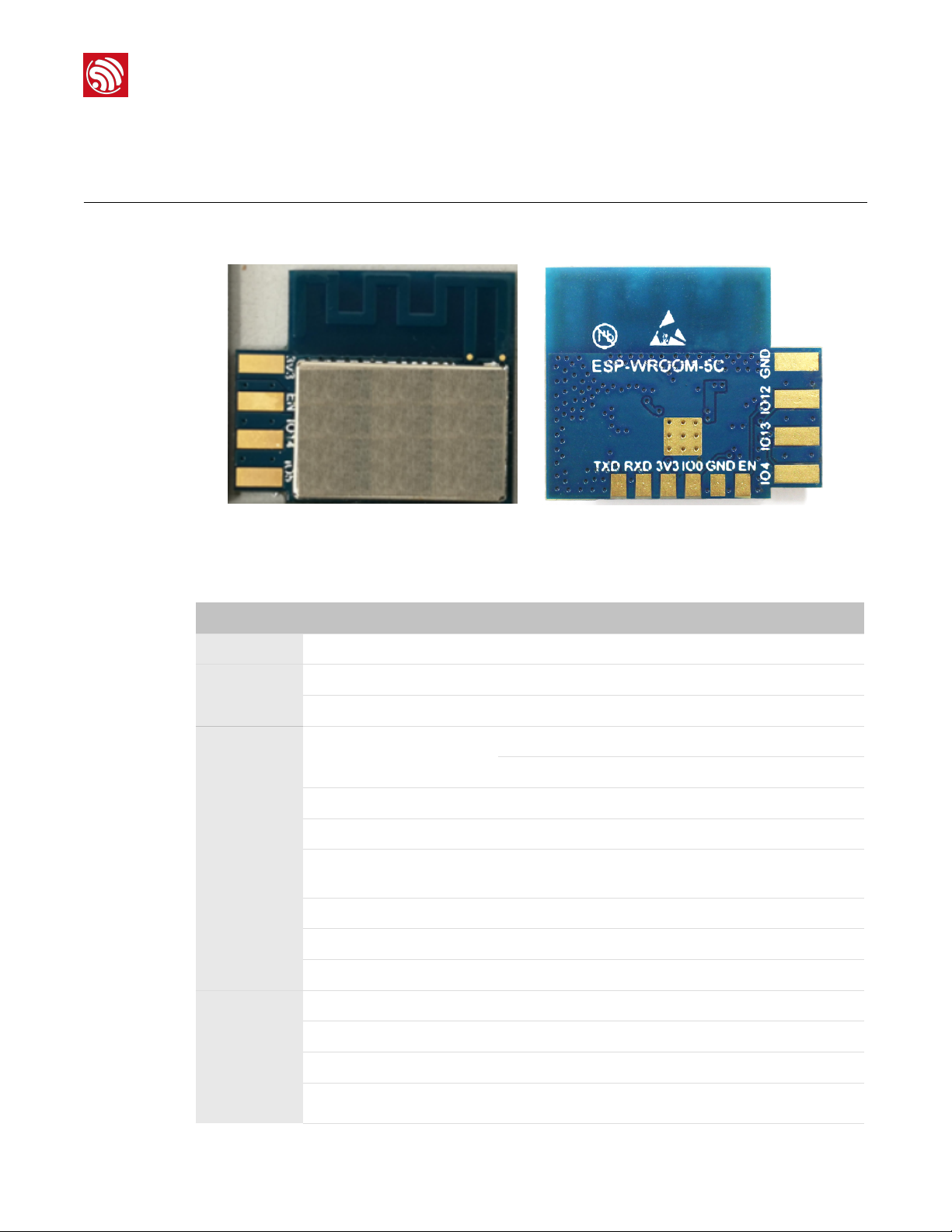
1. Overview
Espressif now offers a side-mounted module ESP-WROOM-5C based on ESP8285.
! !
Figure 1-1. ESP-WROOM-5C Module
Table 1-1. ESP-WROOM-5C Specifications
Categories Items Specifications
T
est Reliablity HTOL/HTSL/uHAST/TCT/ESD
Wi-Fi
Hardware
Wi-Fi protocols
Frequency range 2412 MHz ~ 2462MHz
Peripheral interface
Operating voltage 2.7V ~ 3.6V
Operating current Average: 80 mA
Minimum current delivered by
power supply
Operating temperature range -40°C ~ 105°C
Storage temperature -40°C ~ 105°C
External interface -
802.11 b/g/n20
I2C/IR Remote Control
GPIO/PWM
500 mA
Espressif
Software
Wi-Fi mode Station/SoftAP/SoftAP + Station
Security WPA/WPA2
Encryption WEP/TKIP/AES
Firmware upgrade UART Download/OTA (via network)
2019.01
1
Page 5
1. Overview
Software
!
Categories Items Specifications
Software development
Network protocols IPv4, TCP/UDP/HTTP
User configuration Cloud Server, Android/iOS app
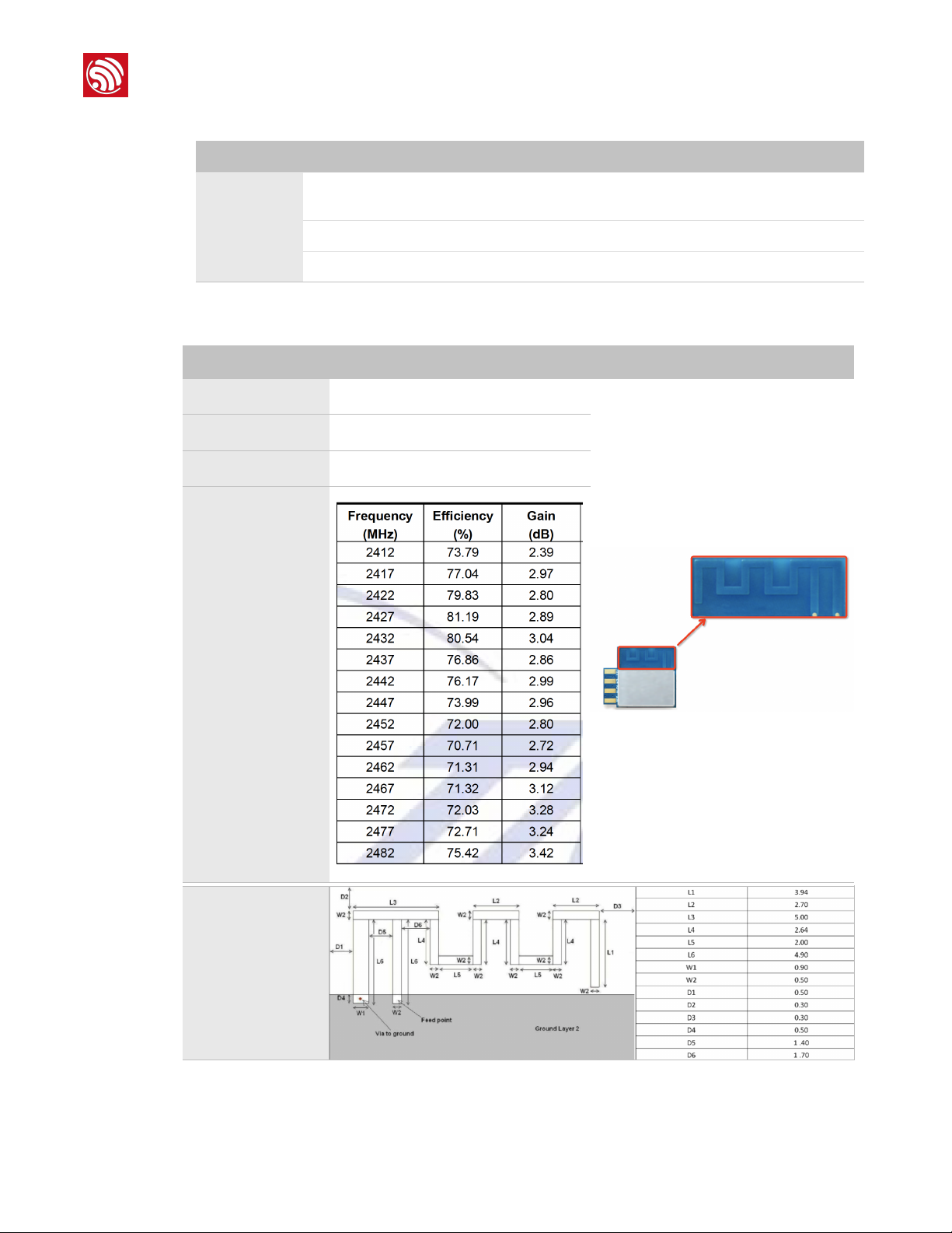
Table 1-2. Antenna Specifications
Parameter Description Image
Model ESP ANT B
Type
Assembly PTH
PCB
Supports Cloud Server Development/SDK for custom
firmware development
Gain
Dimensions
unit:mm
Espressif !2 !
2019.01
Page 6
1. Overview
!
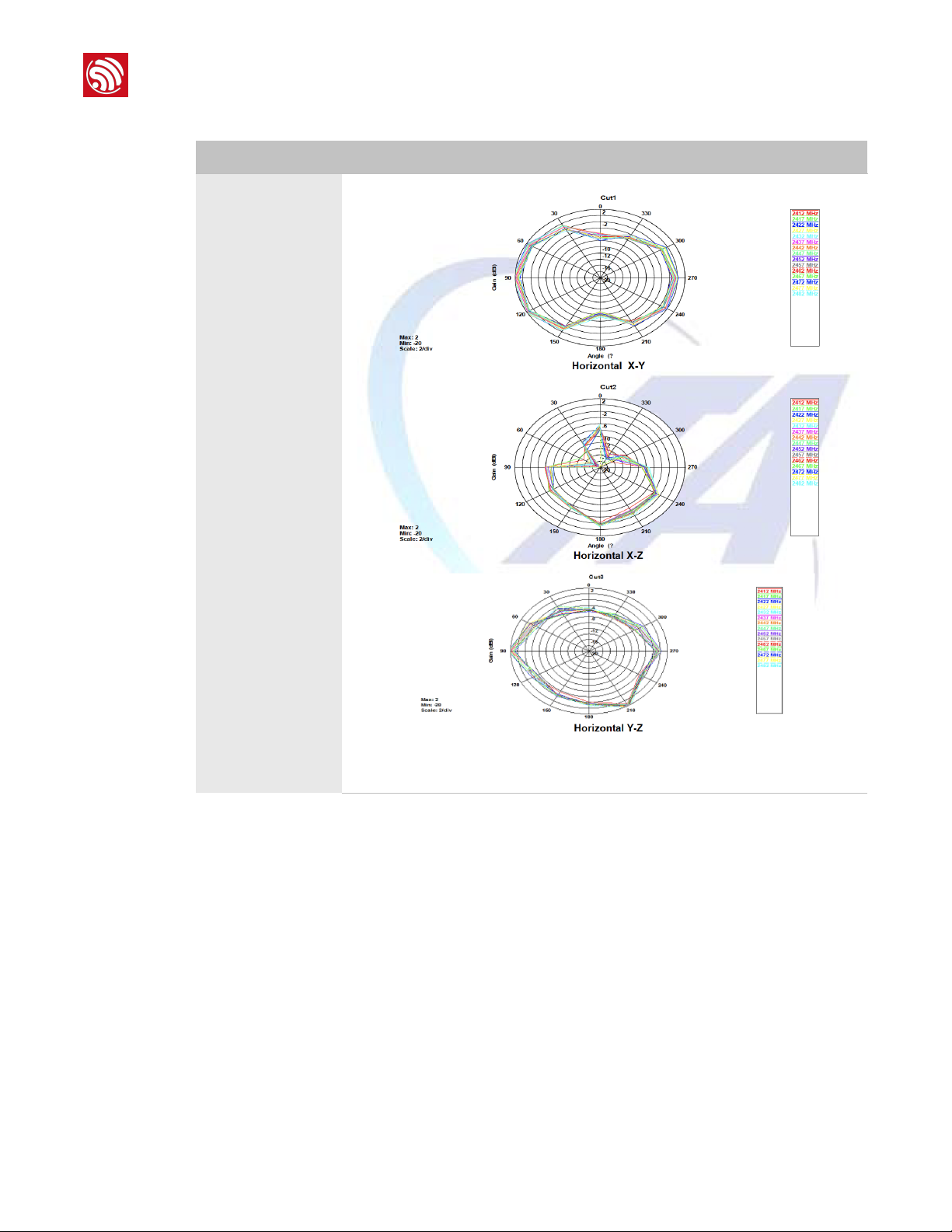
Parameter Description Image
Pattern Plots"
Espressif ! !3
2019.03
Page 7

CONFIDENTIAL
1. Overview
!
Parameter Description Image
Pattern Plots"
Espressif ! !4
2019.03
Page 8

CONFIDENTIAL
2. Pin Description
!
2. Pin Description
Figure 2-1 and Figure 2-2 show the pin distribution of the ESP-WROOM-5C.
!
Figure 2-1. ESP-WROOM-5C Pin Layout (Top View)
!
Figure 2-2. ESP-WROOM-5C Pin Layout (Bottom View)!
Espressif ! !5
2019.01
Page 9

CONFIDENTIAL
2. Pin Description
!
ESP-WROOM-5C has 15 pins. Please see the pin definitions in Table 2-1.
Table 2-1. ESP-WROOM-5C Pin Definitions
No. Pin Name Functional Description
3.3V power supply (VDD)
1 3V3
2 EN Chip enable pin. Active high.
3 IO14 GPIO14
4 IO5 GPIO5
5 GND GND
6 IO12 GPIO12
7 IO13 GPIO13
8 IO4 GPIO4
9 EN Chip enable pin. Active high.
10 GND GND
11 IO0
📖 Note:
It is recommended the maximum output current a power supply
provides be of 500 mA or above.
GPIO0
•
UART download: pull down.
Flash boot: floating or pull up.
•
3.3V power supply (VDD)
12 3V3
13 RXD
14 TXD
15 GND GND
📖 Note:
Pins 1 ~ 8 are pluggable pads that can be welded to your own development board, while pins 9 ~ 15 are
reserved for testing and cannot be welded to the development board.
📖 Note:
It is recommended the maximum output current a power supply
provides be of 500 mA or above.
UART0_RXD, receive end in UART download;
GPIO3
UART0_TXD, transmit end in UART download, floating or pull up;
GPIO1
Espressif ! !6
2019.01
Page 10

3. Functional Description
!
3. Functional Description
3.1. CPU
The ESP8285 integrates a Tensilica L106 32-bit RISC processor, which achieves extra- low
power consumption and reaches a maximum clock speed of 160 MHz. The Real-Time
Operating System (RTOS) and Wi-Fi stack allow 80% of the processing power to be
available for user application programming and development. The CPU includes the
interfaces as below:
Programmable RAM/ROM interfaces (iBus), which can be connected with memory
•
controller, and can also be used to visit flash;
•
Data RAM interface (dBus), which can connected with memory controller;
AHB interface which can be used to visit the register.
•
3.2. Memory
3.2.1. Internal SRAM and ROM
ESP8285 SoC integrates the memory controller including ROM and SRAM. MCU can
access the memory controller through iBus, dBus, and AHB interfaces. All memory units
can be accessed upon request. A memory arbiter determines the running sequence in the
!
arrival order of requests.
3.2.2. SPI Flash
ESP8285 has a built-in SPI flash to store user programs.
Memory size: 1 MB
•
SPI mode: Dual SPI
•
3.3. Crystal Oscillator
ESP-WROOM-5C uses a 26-MHz crystal oscillator. The accuracy of the crystal oscillator
should be ±10 PPM.
When using the download tool, please select the right type of crystal oscillator. In circuit
CONFIDENTIAL
Espressif !
design, capacitors C1 and C2 which connect to the earth are added to the input and
output terminals of the crystal oscillator respectively. The values of the two capacitors can
be flexible, ranging from 6 pF to 22 pF, however, the specific capacitive values depend on
further testing of, and adjustment to, the overall performance of the whole circuit. Normally,
the capacitive values of C1 and C2 are within 10 pF for the 26-MHz crystal oscillator.
2019.01
7
Page 11

!
3.4. Interface Description
Interface Pin Functional Description
3. Functional Description
Table 3-1. Interface Description
PWM
IR
I2C IO14 (SCL), IO5 (SDA)
Interface Pin Functional Description
UART
IO12 (R), IO15 (G),
IO13 (B)
IO14 (IR_T), IO5
(IR_R)
UART0: IO15
(U0TXD), IO13
(U0RXD)
Currently the PWM interface has four channels, but users can extend it
to five channels. PWM interface can realize the control of LED lights,
buzzers, relays, electronic machines, etc.
The functionality of the infrared remote control interface can be realized
via software programming. The interface uses NEC coding, modulation,
and demodulation. The frequency of the modulated carrier signal is 38
kHz. (You can configure this interface to other GPIO)
Connects to external sensors and display screens, etc. (You can
configure this interface to other GPIO)
Communicates with the UART device.
Downloading: U0TXD + U0RXD or GPIO2 + U0RXD
Communicating (UART0): You need to exchange the inner pins of UART
in the software before use IO15 (U0TXD) and IO13 (U0RXD).
CONFIDENTIAL
Espressif ! !8
2019.01
Page 12

4. Electrical Characteristics
!
4. Electrical Characteristics
📖 Note:
Unless otherwise specified, measurements are based on VDD = 3.3V, TA = 25°C.
4.1. Electrical Characteristics
Table 4-1. Electrical Characteristics
Parameter Symbol Min Typ Max Unit
Storage temperatue - –40 Normal 105 ℃
Operating temperature -
Maximum soldering temperature
(Condition: IPC/JEDEC J-STD-020)
Supply voltage VDD 2.7 3.3 3.6 V
Input logic level low V
Input logic level high V
Output logic level low V
Output logic level high V
4.2. Wi-Fi Radio
Description Min Typ Max Unit
Input frequency 2412 -
Input reflection - - –10 dB
Output Impedance -
–
40 20 105 ℃
- - - 260 ℃
IL
IH
OL
OH
Table 4-2. Wi-Fi Radio Characteristics
–0.3 - 0.25 VDD V
0.75 VDD - VDD + 0.3 V
- - 0.1 VDD V
0.8 VDD - - V
2462
50
- Ω
MHz
Espressif
Output Power
802.11b:18.09dBm
RF output power
DSSS, 1 Mbps - –96 - dBm
802.11g:22.84dBm
802.11n20:
22.68dBm
Sensitivity
9
!
2019.01
Page 13

CONFIDENTIAL
!
CCK, 11 Mbps - –87 - dBm
6 Mbps (1/2 BPSK) - –90 - dBm
54 Mbps (3/4 64-QAM) - –73 - dBm
HT20, MCS7 (65 Mbps, 72.2 Mbps) - –69 - dBm
OFDM, 6 Mbps - 37 - dB
OFDM, 54 Mbps - 21 - dB
HT20, MCS0 - 37 - dB
HT20, MCS7 - 20 - dB
4.3. Power Consumption
The following power consumption data were obtained from the tests with a 3.3V power
supply and a voltage stabilizer, in 25°C ambient temperature. All data are based on 50%
duty cycle in continuous transmission mode.
4. Electrical Characteristics
Adjacent channel rejection
Table 4-3. Power Consumption
Modes Min Typ Max Unit
Tx 802.11b, CCK 11 Mbps, P
Tx 802.11g, OFDM 54 Mbps, P
OUT
Tx 802.11n, MCS7, P
Rx 802.11b, 1024 bytes packet length ,
Rx 802.11g, 1024 bytes packet length , –70 dBm - 56 - mA
Rx 802.11n, 1024 bytes packet length , –65 dBm - 56 - mA
Modem-sleep① - 15 - mA
Light-sleep②
Deep-sleep③ - 20 - μA
Power Off - 0.5 - μA
= +13 dBm - 120 - mA
= +17 dBm - 170 - mA
OUT
OUT
= +15 dBm - 140 - mA
–
80 dBm - 50 - mA
- 0.9 - mA
Espressif !
10
2019.01
Page 14

CONFIDENTIAL
!
📖 Notes:
① Modem-sleep mode is used in the applications that require the CPU to be working, as in PWM or I2S
applications. According to 802.11 standards (like U-APSD), it shuts down the Wi-Fi Modem circuit while
maintaining a Wi-Fi connection with no data transmission to optimize power consumption. E.g. in DTIM3,
maintaining a sleep of 300 ms with a wakeup of 3 ms cycle to receive AP’s Beacon packages at interval
requires about 15 mA current.
② During Light-sleep mode, the CPU may be suspended in applications like Wi-Fi switch. Without data
transmission, the Wi-Fi Modem circuit can be turned off and CPU suspended to save power
consumption according to the 802.11 standards (U-APSD). E.g. in DTIM3, maintaining a sleep of 300 ms
with a wakeup of 3 ms to receive AP’s Beacon packages at interval requires about 0.9 mA current.
③ During Deep-sleep mode,Wi-Fi is turned off. For applications with long time lags between data
transmission, e.g. a temperature sensor that detects the temperature every 100s, sleeps for 300s and
wakes up to connect to the AP (taking about 0.3 ~ 1s), the overall average current is less than 1 mA. The
current of 20 μA is acquired at the voltage of 2.5V.
4.4. Reflow Profile
4. Electrical Characteristics
Temperature (℃)
250
217
200
Ramp-up zone
1 ~ 3℃/s
100
50
25
0
0
Ramp-up zone — Temp.: <150℃ Time: 60 ~ 90s Ramp-up rate: 1 ~ 3℃/s
Preheating zone — Temp.: 150 ~ 200℃ Time: 60 ~ 120s Ramp-up rate: 0.3 ~ 0.8℃/s
Reflow zone — Temp.: >217℃ 7LPH60 ~ 90s; Peak Temp.: 235 ~ 250℃ (<245℃ recommended) Time: 30 ~ 70s
Cooling zone — Peak Temp. ~ 180℃ Ramp-down rate: -1 ~ -5℃/s
Solder — Sn&Ag&Cu Lead-free solder (SAC305)
50
Preheating zone
150 ~ 200℃ 60 ~ 120s
100 250
150
200
Peak Temp.
235 ~ 250℃
Reflow zone
!217℃ 60 ~ 90s
Soldering time
> 30s
Figure 4-1. ESP-WROOM-5C Reflow Profile
Cooling zone
-1 ~ -5℃/s
Time (sec.)
Espressif !
11
2019.01
Page 15

CONFIDENTIAL
!
4.5. Electrostatic Discharge
Table 4-4. Electrostatic Discharge Parameters
Name Symbol Reference Level Max Unit
4. Electrical Characteristics
Electrostatic Discharge
(Human - Body Model)
Electrostatic Discharge
(Charged - Device
Model)
ESD
V
(HBM)
ESD
V
(CDM)
Temperature: 23 ± 5℃
Based%on ANSI/ESDA/JEDEC JS - 001 - 2014
Temperature: 23 ± 5℃
Based%on JEDEC EIA/JESD22 - C101F
2 2000
V
C2 500
Espressif
12
2019.01
Page 16

CONFIDENTIAL
7. Dimensions
Unit: mm
T= ± 0.10
ESP-WROOM-5C DIMENSIONS
Antenna Area
Module Length
Module Width
14.00
9.00
0.76
1.18
2.38
3.72
10.41
16.00
3.30
4.34
19.00
Top View
Side View
0.30
3.50
0.50
4.50
5.50
6.20
19.00
8.20
10.61
0.25
1.75
3.11
5.52
10.41
16.00
Antenna Area
Bottom View
15.50
1.18
2.38
3.72
Module Thickness
0.76
PCB Thickness
3.20
0.80
!
5
.
Dimensions
!
Figure 7-1. ESP-WROOM-5C Dimensions!
Espressif !
13
2019.01
Page 17

CONFIDENTIAL
8. Recommended PCB Land Pattern
ESP-WROOM-5C PCB Footprint Dimensions
Unit: mm
T= ±0.1mm
0.47
1.75
3.01
9.37
9.85
3.00
3.15
4.05
4.20
7.20
!
6.
Recommended PCB Land
Pattern
!
Figure 8-1. Recommended PCB Land Pattern of ESP-WROOM-5C!
Espressif !
14
2019.01
Page 18

FCC Statement
Any Changes or modifications not expressly approved by the party responsible for compliance could void
the user’s authority to operate the equipment.
This device complies with part 15 of the FCC Rules. Operation is subject to the following two conditions:
(1) This device may not cause harmful interference, and
(2) This device must accept any interference received, including interference that may cause undesired
operation.
FCC Radiation Exposure Statement:
This equipment complies with FCC radiation exposure limits set forth for an uncontrolled
environment .This equipment should be installed and operated with minimum distance 20cm between the
radiator& your body.
FCC Label Instructions:
The outside of final products that contains this module device must display a label referring to the enclosed
module. This exterior label can use wording such as: “Contains Transmitter Module
FCC ID: 2AC7Z-ESPWROOM5C”,or “Contains
FCC ID: 2AC7Z-ESPWROOM5C”, Any similar wording that expresses the same meaning may be used.
Regulatory Module Integration Instructions
This device complies with part 15.247 of the FCC Rules.
The OEM integrator has to be aware not to provide information to the end user regarding how to install or
remove this RF module in the user’s manual of the end product which integrates this module.
The antenna is integral PCB Antenna and maximum gain is 3.42dBi .
This Wi-Fi module has been granted modular approval for mobile applications. OEM integrators
for host products may use the module in their final products without additional FCC certification if they
meet the following conditions. Otherwise, additional FCC approvals must be obtained.
The host product with the module installed must be evaluated for simultaneous
transmission requirements.
The user’s manual for the host product must clearly indicate the operating requirements
and conditions that must be observed to ensure compliance with current FCC RF exposure guidelines.
To comply with FCC regulations limiting both maximum RF output power and human
exposure to RF radiation, use this module only with the included onboard antenna.
The final host / module combination may also need to be evaluated against the FCC Part 15B
criteria for unintentional radiators in order to be properly authorized for operation as a Part 15
digital device.
Disclaimer and Copyright Notice
Information in this document, including URL references, is subject to change without
notice.
THIS DOCUMENT IS PROVIDED AS IS WITH NO WARRANTIES WHATSOEVER,
INCLUDING ANY WARRANTY OF MERCHANTABILITY, NON-INFRINGEMENT, FITNESS
FOR ANY PARTICULAR PURPOSE, OR ANY WARRANTY OTHERWISE ARISING OUT
OF ANY PROPOSAL, SPECIFICATION OR SAMPLE.
All liability, including liability for infringement of any proprietary rights, relating to use of
information in this document is disclaimed. No licenses express or implied, by estoppel or
otherwise, to any intellectual property rights are granted herein.
The Wi-Fi Alliance Member logo is a trademark of the Wi-Fi Alliance. The Bluetooth logo is
a registered trademark of Bluetooth SIG.
Espressif IoT Team"
www.espressif.com
All trade names, trademarks and registered trademarks mentioned in this document are
property of their respective owners, and are hereby acknowledged.
Copyright © 2019 Espressif Inc. All rights reserved.
 Loading...