

Page 1

!
Version 2.1.0
Copyright © 2017
ESP8266 AT Instruction Set
Page 2

About This Guide
This document provides AT commands list based on ESP8266_NONOS_SDK.
The document is structured as follows:
Release Notes
Chapter
Title
Content
Chapter 1
Overview
Provides instructions on user-defined AT commands
and downloading of AT firmware.
Chapter 2
Command Description
Gives a basic description of AT commands.
Chapter 3
Basic AT Commands
Lists AT commands of basic functions.
Chapter 4
Wi-Fi AT Commands
Lists Wi-Fi-related AT commands.
Chapter 5
TCP/IP-Related AT Commands
Lists TCP/IP-related AT commands.
Chapter 6
Appendix
Lists the AT commands of which the configuration is
saved in the flash.
Chapter 7
Q & A
Provides information on where and how to consult
questions about ESP8266 AT commands.
Date
Version
Release notes
2016.04
V1.5.3
First Release.
2016.05
V1.5.4
Updated Section 5.2.16 and Section 5.2.19
2016.07
V2.0.0
Added Section 3.2.11, updated Section 1.2
2017.05
V2.1.0
Updated Section 3.2, Section 4.1 and Section 5.2.
Page 3

录
1. Overview 1 ................................................................................................................................................
1.1. User-Defined AT Commands! 1"......................................................................................................................
1.2. Downloading AT Firmware into the Flash! 2"...................................................................................................
1.2.1. 4 Mbit Flash! 2"...................................................................................................................................
1.2.2. 8 Mbit Flash! 2"...................................................................................................................................
1.2.3. 16 Mbit Flash, Map: 512 KB + 512 KB! 3"..........................................................................................
1.2.4. 16 Mbit Flash, Map: 1024 KB + 1024 KB! 3"......................................................................................
1.2.5. 32 Mbit Flash, Map: 512 KB + 512 KB! 4"..........................................................................................
1.2.6. 32 Mbit Flash, Map: 1024 KB + 1024 KB! 4"......................................................................................
2. Command Description 6 ..........................................................................................................................
3. Basic AT Commands 7 .............................................................................................................................
3.1. Overview! 7".....................................................................................................................................................
3.2. Commands! 8".................................................................................................................................................
3.2.1. AT—Tests AT Startup! 8".....................................................................................................................
3.2.2. AT+RST—Restarts the Module! 8".....................................................................................................
3.2.3. AT+GMR—Checks Version Information! 8"........................................................................................
3.2.4. AT+GSLP—Enters Deep-sleep Mode! 8"...........................................................................................
3.2.5. ATE—AT Commands Echoing! 9".......................................................................................................
3.2.6. AT+RESTORE—Restores the Factory Default Settings! 9"................................................................
3.2.7. AT+UART—UART Configuration! 9"...................................................................................................
3.2.8. AT+UART_CUR—Current UART Configuration; Not Saved in the Flash! 11"....................................
3.2.9. AT+UART_DEF—Default UART Configuration; Saved in the Flash! 12".............................................
3.2.10. AT+SLEEP—Configures the Sleep Modes! 13"..................................................................................
3.2.11. AT+WAKEUPGPIO—Configures a GPIO to Wake ESP8266 up from Light-sleep Mode! 13"............
3.2.12. AT+RFPOWER—Sets the Maximum Value of RF TX Power! 14".......................................................
3.2.13. AT+RFVDD—Sets RF TX Power According to VDD33! 14"................................................................
3.2.14. AT+RFAUTOTRACE—Sets RF Frequency Offset Trace! 15"..............................................................
3.2.15. AT+SYSRAM—Checks the Remaining Space of RAM! 15"...............................................................
3.2.16. AT+SYSADC—Checks the Value of ADC! 15"....................................................................................
3.2.17. AT+SYSIOSETCFG—Configures IO Working Mode! 16"....................................................................
Page 4

3.2.18. AT+SYSIOGETCFG—Checks the Working Modes of IO Pins! 16".....................................................
3.2.19. AT+SYSGPIODIR—Configures the Direction of a GPIO! 16".............................................................
3.2.20. AT+SYSGPIOWRITE—Configures the Output Level of a GPIO! 17"..................................................
3.2.21. AT+SYSGPIOREAD—Reads the GPIO Input Level! 17".....................................................................
4. Wi-Fi AT Commands 19 ...........................................................................................................................
4.1. Overview! 19"...................................................................................................................................................
4.2. Commands! 21"...............................................................................................................................................
4.2.1. AT+CWMODE—Sets the Wi-Fi Mode (Station/SoftAP/Station+SoftAP)! 21".....................................
4.2.2. AT+CWMODE_CUR—Sets the Current Wi-Fi mode; Configuration Not Saved in the Flash! 21"......
4.2.3. AT+CWMODE_DEF—Sets the Default Wi-Fi mode; Configuration Saved in the Flash! 21"..............
4.2.4. AT+CWJAP—Connects to an AP! 22"................................................................................................
4.2.5. AT+CWJAP_CUR—Connects to an AP; Configuration Not Saved in the Flash! 23"..........................
4.2.6. AT+CWJAP_DEF—Connects to an AP; Configuration Saved in the Flash! 23".................................
4.2.7. AT+CWLAPOPT—Sets the Configuration for the Command AT+CWLAP! 25"..................................
4.2.8. AT+CWLAP—Lists Available APs! 26"................................................................................................
4.2.9. AT+CWQAP—Disconnects from the AP! 26".....................................................................................
4.2.10. AT+CWSAP—Configures the ESP8266 SoftAP! 27"..........................................................................
4.2.11. AT+CWSAP_CUR—Configures the ESP8266 SoftAP; Configuration Not Saved in the Flash! 27"....
4.2.12. AT+CWSAP_DEF—Configures the ESP8266 SoftAP; Configuration Saved in the Flash! 28"...........
4.2.13. AT+CWLIF—IP of Stations to Which the ESP8266 SoftAP is Connected! 29"...................................
4.2.14. AT+CWDHCP—Enables/Disables DHCP! 29"....................................................................................
4.2.15. AT+CWDHCP_CUR—Enables/Disables DHCP; Configuration Not Saved in the Flash! 29".............
4.2.16. AT+CWDHCP_DEF—Enables/Disables DHCP; Configuration Saved in the Flash! 30".....................
4.2.17. AT+CWDHCPS_CUR—Sets the IP Address Allocated by ESP8266 SoftAP DHCP;
Configuration Not Saved in Flash! 31"...............................................................................................................
4.2.18. AT+CWDHCPS_DEF—Sets the IP Address Allocated by ESP8266 SoftAP DHCP; Configuration
Saved in Flash! 31".............................................................................................................................................
4.2.19. AT+CWAUTOCONN—Auto-Connects to the AP or Not! 32".............................................................
4.2.20. AT+CIPSTAMAC—Sets the MAC Address of the ESP8266 Station! 32"...........................................
4.2.21. AT+CIPSTAMAC_CUR—Sets the MAC Address of the ESP8266 Station; Configuration Not
Saved in the Flash! 32".......................................................................................................................................
4.2.22. AT+CIPSTAMAC_DEF—Sets the MAC Address of the ESP8266 Station; Configuration Saved in
the Flash! 33"......................................................................................................................................................
4.2.23. AT+CIPAPMAC—Sets the MAC Address of the ESP8266 SoftAP! 33"..............................................
Page 5

4.2.24. AT+CIPAPMAC_CUR—Sets the MAC Address of the ESP8266 SoftAP; Configuration Not
Saved in the Flash! 34".......................................................................................................................................
4.2.25. AT+CIPAPMAC_DEF—Sets the MAC Address of the ESP8266 SoftAP; Configuration Saved in
Flash! 34"............................................................................................................................................................
4.2.26. AT+CIPSTA—Sets the IP Address of the ESP8266 Station! 35"........................................................
4.2.27. AT+CIPSTA_CUR—Sets the IP Address of the ESP8266 Station; Configuration Not Saved in
the Flash! 35"......................................................................................................................................................
4.2.28. AT+CIPSTA_DEF—Sets the IP Address of the ESP8266 Station; Configuration Saved in the
Flash! 36"............................................................................................................................................................
4.2.29. AT+CIPAP—Sets the IP Address of the ESP8266 SoftAP! 36"..........................................................
4.2.30. AT+CIPAP_CUR—Sets the IP Address of the ESP8266 SoftAP; Configuration Not Saved in the
Flash! 37"............................................................................................................................................................
4.2.31. AT+CIPAP_DEF—Sets the IP Address of the ESP8266 SoftAP; Configuration Saved in the Flash
! 37"....................................................................................................................................................................
4.2.32. AT+CWSTARTSMART—Starts SmartConfig! 38"...............................................................................
4.2.33. AT+CWSTOPSMART—Stops SmartConfig! 38"................................................................................
4.2.34. AT+CWSTARTDISCOVER—Enables the Mode that ESP8266 can be Found by WeChat! 39"..........
4.2.35. AT+CWSTOPDISCOVER—Disables the Mode that ESP8266 can be Found by WeChat! 39"..........
4.2.36. AT+WPS—Enables the WPS Function! 39"........................................................................................
4.2.37. AT+MDNS—Configures the MDNS Function! 40"..............................................................................
4.2.38. AT+CWHOSTNAME—Configures the Name of ESP8266 Station! 40"..............................................
5. TCP/IP-Related AT Commands 41 ..........................................................................................................
5.1. Overview! 41"...................................................................................................................................................
5.2. Commands! 42"...............................................................................................................................................
5.2.1. AT+CIPSTATUS—Gets the Connection Status! 42"...........................................................................
5.2.2. AT+CIPDOMAIN—DNS Function! 42"................................................................................................
5.2.3. AT+CIPSTART—Establishes TCP Connection, UDP Transmission or SSL Connection! 43".............
5.2.4. AT+CIPSSLSIZE—Sets the Size of SSL Buffer! 45"...........................................................................
5.2.5. AT+CIPSEND—Sends Data! 45".........................................................................................................
5.2.6. AT+CIPSENDEX—Sends Data! 46"....................................................................................................
5.2.7. AT+CIPSENDBUF—Writes Data into the TCP-Send-Buffer! 46"........................................................
5.2.8. AT+CIPBUFRESET—Resets the Segment ID Count! 47"...................................................................
5.2.9. AT+CIPBUFSTATUS—Checks the Status of the TCP-Send-Buffer! 48"............................................
5.2.10. AT+CIPCHECKSEQ—Checks If a Specific Segment Was Successfully Sent! 48"............................
5.2.11. AT+CIPCLOSE—Closes the TCP/UDP/SSL Connection! 49"............................................................
5.2.12. AT+CIFSR—Gets the Local IP Address! 49"......................................................................................
Page 6

5.2.13. AT+CIPMUX—Enable or Disable Multiple Connections! 49"..............................................................
5.2.14. AT+CIPSERVER—Deletes/Creates TCP Server! 50"..........................................................................
5.2.15. AT+CIPMODE—Sets Transmission Mode! 50"...................................................................................
5.2.16. AT+SAVETRANSLINK—Saves the Transparent Transmission Link in Flash! 51"...............................
5.2.17. AT+CIPSTO—Sets the TCP Server Timeout! 52"...............................................................................
5.2.18. AT+PING—Ping Packets! 52".............................................................................................................
5.2.19. AT+CIUPDATE—Updates the Software Through Wi-Fi! 53"...............................................................
5.2.20. AT+CIPDINFO—Shows the Remote IP and Port with +IPD! 53"........................................................
5.2.21. +IPD—Receives Network Data! 53"...................................................................................................
5.2.22. AT+CIPSNTPCFG—Sets the Configuration of SNTP! 54"..................................................................
5.2.23. AT+CIPSNTPTIME—Checks the SNTP Time! 54"..............................................................................
5.2.24. AT+CIPDNS_CUR—Sets User-defined DNS Servers; Configuration Not Saved in the Flash! 54"....
5.2.25. AT+CIPDNS_DEF—Sets User-defined DNS Servers; Configuration Saved in the Flash! 55"............
6. Appendix 56 .............................................................................................................................................
7. Q&A 57......................................................................................................................................................
Page 7

!
1. Overview
1. Overview
This document provides AT commands based on ESP8266_NONOS_SDK and explain how to use
them. AT command set is divided into: Basic AT commands, Wi-Fi AT commands, and TCP/IP AT
commands.
1.1. User-Defined AT Commands
Please use only English letters when naming user-defined AT commands. The AT command name
must NOT contain characters or numbers.
AT firmware is based on ESP8266_NONOS_SDK. Espressif Systems’ AT commands are provided in
libat.a, which is included in the AT BIN firmware. Examples of customized, user-defined AT
commands are provided in ESP8266_NONOS_SDK/example/at.
Examples of implementing user-defined AT commands are provided in /ESP8266_NONOS_SDK/
examples/at/user/user_main.c. The structure, at_funcationType, is used to define four types of a
command, for details of which please refer to the following table.
Definition
Type
Description
at_testCmd
Test
AT Command
AT+TEST=?
Registered Callback In Example
at_testCmdTest
Function Design
Return the value"range of parameters
If at_testCmd is registered as NULL, there will be no testing command.
at_queryCmd
Query
AT Command
AT+TEST?
Registered Callback In Example
at_queryCmdTest
Function Design
Return the current value
If at_queryCmd is registered as NULL, there will be no Query Command.
at_setupCmd
Set
AT Command
AT+TEST=parameter1, parameter2, …
Registered Callback In Example
at_setupCmdTest
Function Design
Set configuration
If at_setupCmd is registered as NULL, there will be no setup command.
at_exeCmd
Execute
AT Command
AT+TEST
Registered Callback In Example
at_exeCmdTest
Function Design
Execute an action
If at_exeCmd is registered as NULL, there will be no execution command.
Espressif
! /!1 58
2017.05
Page 8
!
1. Overview
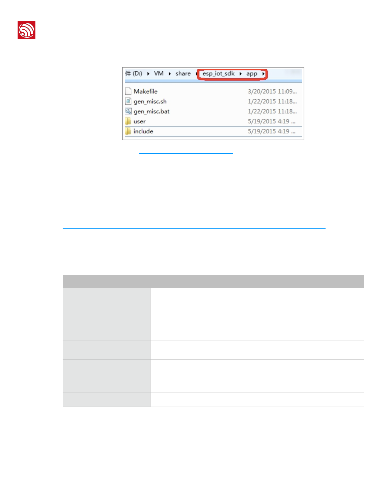
All the files in folder at should be copied to the folder app in ESP8266_NONOS_SDK if users need to
compile the AT firmware.
!
For details please refer to ESP8266 Getting Started Guide.
1.2. Downloading AT Firmware into the Flash
Please refer to ESP8266_NONOS_SDK/bin/at/readme.txt for instructions on how to download AT
firmware into flash. Please use Espressif’s official Flash Download Tools to download the firmware.
Make sure you select the corresponding flash size.
Espressif’s official Flash Download Tools:"
http://espressif.com/en/support/download/other-tools?keys=&field_type_tid%5B%5D=14.
1.2.1. 4 Mbit Flash
With the release of ESP8266_NONOS_SDK_V2.0.0, AT_V1.3, AT firmware can use 4-Mbit flash but
does not supports FOTA (upgrade AT firmware through Wi-Fi) function.
1.2.2. 8 Mbit Flash
If the flash size is 8 Mbit or larger, users can use boot mode which supports AT firmware upgrade
feature through Wi-Fi by command AT+CIUPDATE. Use Espressif Flash download tool and select flash
size: 8 Mbit.
BIN
Address
Description
blank.bin
0x78000
Initializes the RF_CAL parameter area.
esp_init_data_default.bin
0x7C000
Stores the default RF parameter values; the BIN has to be
downloaded into flash at least once.
If the RF_CAL parameter area is initialized, this BIN has to be
downloaded too.
blank.bin
0x7A000
Initializes the flash user parameter area; for more details please
see Appendix.
blank.bin
0x7E000
Initializes Flash system parameter area; for more details please
see Appendix.
eagle.flash.bin
0x00000
In /bin/at/noboot.
eagle.irom0text.bin
0x10000
In /bin/at/noboot.
Espressif
! /!2 58
2017.05
Page 9

!
1. Overview
1.2.3. 16 Mbit Flash, Map: 512 KB + 512 KB
Use Espressif Flash download tool and select flash size: 16 Mbit.
1.2.4. 16 Mbit Flash, Map: 1024 KB + 1024 KB
Use Espressif Flash download tool and select flash size: 16 Mbit-C1.
BIN
Address
Description
blank.bin
0xFB000
Initializes the RF_CAL parameter area.
esp_init_data_default.bin
0xFC000
Initializes the RF_CAL parameter area.
blank.bin
0x7E000
Stores the default RF parameter values; the BIN has to be
downloaded into flash at least once.
If the RF_CAL parameter area is initialized, this BIN has to be
downloaded too.
blank.bin
0xFE000
Initializes the flash user parameter area; for more details please
see Appendix.
boot.bin
0x00000
In /bin/at
user1.1024.new.2.bin
0x01000
In /bin/at/512+512
BIN
Address
Description
blank.bin
0x1FB000
Initializes RF_CAL parameter area.
esp_init_data_default.bin
0x1FC000
Stores default RF parameter values, has to be downloaded into
flash at least once.
If the RF_CAL parameter area is initialized, this bin has to be
downloaded too.
blank.bin
0x7E000
Initializes Flash user parameter area, more details in Appendix.
blank.bin
0x1FE000
Initializes Flash system parameter area, more details in
Appendix.
boot.bin
0x00000
In /bin/at.
user1.1024.new.2.bin
0x01000
In /bin/at/512+512.
BIN
Address
Description
blank.bin
0x1FB000
Initializes RF_CAL parameter area.
esp_init_data_default.bin
0x1FC000
Stores default RF parameter values, has to be downloaded into
flash at least once.
If the RF_CAL parameter area is initialized, this bin has to be
downloaded too.
blank.bin
0xFE000
Initializes Flash user parameter area, more details in Appendix.
BIN
Espressif
! /!3 58
2017.05
Page 10

!
1. Overview
1.2.5. 32 Mbit Flash, Map: 512 KB + 512 KB
Use Espressif Flash download tool and select flash size: 32 Mbit.
1.2.6. 32 Mbit Flash, Map: 1024 KB + 1024 KB
Use Espressif Flash download tool and select flash size: 32 Mbit-C1.
blank.bin
0x1FE000
Initializes Flash system parameter area, more details in
Appendix.
boot.bin
0x00000
In /bin/at.
user1.2048.new.5.bin
0x01000
In /bin/at/1024+1024.
Address
Description
BIN
BIN
Address
Description
blank.bin
0x3FB000
Initializes RF_CAL parameter area.
esp_init_data_default.bin
0x3FC000
Stores default RF parameter values, has to be downloaded into
flash at least once.
If the RF_CAL parameter area is initialized, this bin has to be
downloaded too.
blank.bin
0x7E000
Initializes Flash user parameter area, more details in Appendix.
blank.bin
0x3FE000
Initializes Flash system parameter area, more details in
Appendix.
boot.bin
0x00000
In /bin/at.
user1.1024.new.2.bin
0x01000
In /bin/at/512+512.
BIN
Address
Description
blank.bin
0x3FB000
Initializes RF_CAL parameter area
esp_init_data_default.bin
0x3FC000
Stores default RF parameter values, has to be downloaded into
flash at least once.
If the RF_CAL parameter area is initialized, this bin has to be
downloaded too.
blank.bin
0xFE000
Initializes Flash user parameter area, more details in Appendix.
blank.bin
0x3FE000
Initializes Flash system parameter area, more details in
Appendix.
boot.bin
0x00000
In /bin/at.
user1.2048.new.5.bin
0x01000
In /bin/at/1024+1024.
Espressif
! /!4 58
2017.05
Page 11

!
1. Overview
⚠ Notes:
•
Please make sure that correct BIN (/ESP8266_NONOS_SDK/bin/at) is already in the chip (ESP8266) before using
the AT commands listed in this document.
•
AT firmware uses priority levels 0 and 1 of system_os_task, so only one task of priority 2 is allowed to be set up by
the user.
• AT returns messages below to show status of the ESP8266 Station’s Wi-Fi connection.
‣ Wi-FiCONNECTED: Wi-Fi is connected.
‣ Wi-FiGOTIP: the ESP8266 Station has got the IP from the AP.
‣ Wi-FiDISCONNECT: Wi-Fi is disconnected.
Espressif
! /!5 58
2017.05
Page 12

!
2. Command Description
2. Command Description
Each command set contains four types of AT commands.
Type
Command Format
Description
Test Command
AT+<x>=?
Queries the Set Commands’ internal parameters and their range of
values.
Query Command
AT+<x>?
Returns the current value of parameters.
Set Command
AT+<x>=<…>
Sets the value of user-defined parameters in commands, and runs these
commands.
Execute Command
AT+<x>
Runs commands with no user-defined parameters.
⚠ Notice:
•
Not all AT commands support all four variations mentioned above.
•
Square brackets [ ] designate the default value; it is either not required or may not appear.
• String values need to be included in double quotation marks, for example: AT+CWSAP="ESP756290","21030826",
1,4.
• The default baud rate is 115200.
• AT commands have to be capitalized, and must end with a new line (CR LF).
Espressif
! /!6 58
2017.05
Page 13

!
3. Basic AT Commands
3. Basic AT Commands
3.1. Overview
Commands
Description
AT
Tests AT startup.
AT+RST
Restarts the module.
AT+GMR
Checks version information.
AT+GSLP
Enters Deep-sleep mode.
ATE
Configures echoing of AT commands.
AT+RESTORE
Restores the factory default settings of the module.
AT+UART
UART configuration. [@deprecated]
AT+UART_CUR
The current UART configuration.
AT+UART_DEF
The default UART configuration, saved in flash.
AT+SLEEP
Configures the sleep modes.
AT+WAKEUPGPIO
Configures a GPIO to wake ESP8266 up from Light-sleep mode.
AT+RFPOWER
Sets the maximum value of the RF TX Power.
AT+RFVDD
Sets the RF TX Power according to VDD33.
AT+RFAUTOTRACE
Sets RF frequency offset trace.
AT+SYSRAM
Checks the available RAM size.
AT+SYSADC
Checks the ADC value.
AT+SYSIOSETCFG
Sets configuration of IO pins.
AT+SYSIOGETCFG
Gets configuration of IO pins.
AT+SYSGPIODIR
Configures the direction of GPIO.
AT+SYSGPIOWRITE
Configures the GPIO output level
AT+SYSGPIOREAD
Checks the GPIO input level.
Espressif
! /!7 58
2017.05
Page 14

!
3. Basic AT Commands
3.2. Commands
3.2.1. AT—Tests AT Startup
3.2.2. AT+RST—Restarts the Module
3.2.3. AT+GMR—Checks Version Information
3.2.4. AT+GSLP—Enters Deep-sleep Mode
Execute Command
AT
Response
OK
Parameters
-
Execute Command
AT+RST
Response
OK
Parameters
-
Execute Command
AT+GMR
Response
<ATversioninfo>
<SDKversioninfo>
<compiletime>
OK
Parameters
• <ATversioninfo>:information about the AT version.
• <SDKversioninfo>:information about the SDK version.
• <compiletime>: the duration of time for compiling the BIN.
Set Command
AT+GSLP=<time>
Response
<time>
OK
Parameters
<time>: the duration of ESP8266’s sleep. Unit: ms.
ESP8266 will wake up after Deep-sleep for as many milliseconds (ms) as <time>
indicates.
Note
A minor adjustment has to be made before the module enter the Deep-sleep mode, i.e.,
connecting XPD_DCDC to EXT_RSTB via a 0-ohm resistor.
Espressif
! /!8 58
2017.05
Page 15

!
3. Basic AT Commands
3.2.5. ATE—AT Commands Echoing
3.2.6. AT+RESTORE—Restores the Factory Default Settings
3.2.7. AT+UART—UART Configuration
[@deprecated] This command is deprecated. Please use AT+UART_CUR or AT+UART_DEF instead.
Execute Command
ATE
Response
OK
Parameters
•
ATE0: Switches echo off.
•
ATE1: Switches echo on.
Note
This command ATE is used to trigger command echo. It means that entered commands
can be echoed back to the sender when ATE command is used. Two parameters are
possible. The command returns OK in normal cases and ERROR when a parameter other
than 0 or 1 was specified.
Execute Command
AT+RESTORE
Response
OK
Note
The execution of this command will reset all parameters saved in flash, and restore the
factory default settings of the module. The chip will be restarted when this command is
executed.
Command
Query Command:
AT+UART?
Set Command:
AT+UART=<baudrate>,<databits>,<stopbits
>,<parity>,<flowcontrol>
Response
+UART:<baudrate>,<databits>,<stopbits>,<parity>,
<flowcontrol>
OK
OK
Note
Command AT+UART? will return the actual value of UART
configuration parameters, which may have allowable
errors compared with the set value.
For example, if the UART baud rate is set as 115200,
the baud rate returned by using command AT+UART?
could be 115273.
-
Espressif
! /!9 58
2017.05
Page 16

!
3. Basic AT Commands
Parameters
• <baudrate>: UART baud rate
• <databits>: data bits
‣ 5: 5-bit data
‣ 6: 6-bit data
‣ 7: 7-bit data
‣ 8: 8-bit data
• <stopbits>: stop bits
‣ 1: 1-bit stop bit
‣ 2: 1.5-bit stop bit
‣ 3: 2-bit stop bit
• <parity>: parity bit
‣ 0: None
‣ 1: Odd
‣ 2: Even
• <flowcontrol>: flow control
‣ 0: flow control is not enabled
‣ 1: enable RTS
‣ 2: enable CTS
‣ 3: enable both RTS and CTS
Notes
1. The configuration changes will be saved in the user parameter area in the flash, and will still be valid
when the chip is powered on again.
2. The use of flow control requires the support of hardware:
‣ MTCK is UART0 CTS
‣ MTDO is UART0 RTS
3. The range of baud rates supported: 110~115200*40.
Example
AT+UART=115200,8,1,0,3
Espressif
! /!10 58
2017.05
Page 17

!
3. Basic AT Commands
3.2.8. AT+UART_CUR—Current UART Configuration; Not Saved in the Flash
Command
Query Command:
AT+UART_CUR?
Set Command:
AT+UART_CUR=<baudrate>,<databits>,<stop
bits>,<parity>,<flowcontrol>
Response
+UART_CUR:<baudrate>,<databits>,<stopbits>,<pari
ty>,<flowcontrol>
OK
OK
Note
Command AT+UART_CUR? will return the actual value of
UART configuration parameters, which may have
allowable errors compared with the set value because of
the clock division.
For example, if the UART baud rate is set as 115200,
the baud rate returned by using command AT+UART_CUR?
could be 115273.
-
Parameters
• <baudrate>: UART baud rate
• <databits>: data bits
‣ 5: 5-bit data
‣ 6: 6-bit data
‣ 7: 7-bit data
‣ 8: 8-bit data
• <stopbits>: stop bits
‣ 1: 1-bit stop bit
‣ 2: 1.5-bit stop bit
‣ 3: 2-bit stop bit
• <parity>: parity bit
‣ 0: None
‣ 1: Odd
‣ 2: Even
• <flowcontrol>: flow control
‣ 0: flow control is not enabled
‣ 1: enable RTS
‣ 2: enable CTS
‣ 3: enable both RTS and CTS
Notes
1. The configuration changes will NOT be saved in the flash.
2. The use of flow control requires the support of hardware:
‣ MTCK is UART0 CTS
‣ MTDO is UART0 RTS
3. The range of baud rates supported: 110~115200*40.
Example
AT+UART_CUR=115200,8,1,0,3
Espressif
! /!11 58
2017.05
Page 18

!
3. Basic AT Commands
3.2.9. AT+UART_DEF—Default UART Configuration; Saved in the Flash
Command
Query Command:
AT+UART_DEF?
Set Command:
AT+UART_DEF=<baudrate>,<databits>,<stopbits>
,<parity>,<flowcontrol>
Response
+UART_DEF:<baudrate>,<databits>,<stopbits>,<
parity>,<flowcontrol>
OK
OK
Parameter
• <baudrate>: UART baud rate
• <databits>: data bits
‣
5: 5-bit data
‣
6: 6-bit data
‣
7: 7-bit data
‣
8: 8-bit data
• <stopbits>: stop bits
‣
1: 1-bit stop bit
‣
2: 1.5-bit stop bit
‣
3: 2-bit stop bit
• <parity>: parity bit
‣
0: None
‣
1: Odd
‣
2: Even
• <flowcontrol>: flow control
‣
0: flow control is not enabled
‣
1: enable RTS
‣
2: enable CTS
‣
3: enable both RTS and CTS
Notes
1. The configuration changes will be saved in the user parameter area in the flash, and will still be valid
when the chip is powered on again.
2. The use of flow control requires the support of hardware:
‣ MTCK is UART0 CTS
‣ MTDO is UART0 RTS
3. The range of baud rates supported: 110~115200*40.
Example
AT+UART_DEF=115200,8,1,0,3
Espressif
! /!12 58
2017.05
Page 19

!
3. Basic AT Commands
3.2.10. AT+SLEEP—Configures the Sleep Modes
3.2.11. AT+WAKEUPGPIO—Configures a GPIO to Wake ESP8266 up from Light-sleep Mode
Command
Query Command:
AT+SLEEP?
Set Command:
AT+SLEEP=<sleepmode>
Response
+SLEEP:<sleepmode>
OK
OK
or
ERROR
Parameter
<sleepmode>:
‣ 0: disables sleep mode
‣ 1: Light-sleep mode
‣ 2: Modem-sleep mode
Notes
This command can only be used in Station mode. Modem-sleep is the default sleep mode.
Example
AT+SLEEP=0
Command
AT+WAKEUPGPIO=<enable>,<trigger_GPIO>,<trigger_level>[,<awake_GPIO>,<awake_level>]
Response
OK
Parameter
• <enable>
‣ 0: ESP8266 can NOT be woken up from light-sleep by GPIO.
‣
1: ESP8266 can be woken up from light-sleep by GPIO.
• <trigger_GPIO>
‣
Sets the GPIO to wake ESP8266 up; range of value: [0, 15].
• <trigger_level>
‣ 0: The GPIO wakes up ESP8266 on low level.
‣ 1: The GPIO wakes up ESP8266 on high level.
• [<awake_GPIO>]
‣ Optional; this parameter is used to set a GPIO as a flag of ESP8266’s being awoken form
Light-sleep; range of value: [0, 15].
• [<awake_level>]
‣ Optional;
‣ 0: The GPIO is set to be low level after the wakeup process.
‣ 1: The GPIO is set to be high level after the wakeup process.
Notes
•
The value of <trigger_GPIO> and <awake_GPIO> in the command should not be the same.
•
After being woken up by <trigger_GPIO> from Light-sleep, when the ESP8266 attempts to
sleep again, it will check the status of the <trigger_GPIO>:
‣
if it is still in the wakeup status, the EP8266 will enter Modem-sleep mode instead;
‣
if it is NOT in the wakeup status, the ESP8266 will enter Light-sleep mode.
Espressif
! /5813
2017.05
Page 20

!
3. Basic AT Commands
3.2.12. AT+RFPOWER—Sets the Maximum Value of RF TX Power
3.2.13. AT+RFVDD—Sets RF TX Power According to VDD33
Example
• Set ESP8266 to be woken from Light-sleep, when GPIO0 is on low level:
AT+WAKEUPGPIO=1,0,0
• Set ESP8266 to be woken from Light-sleep, when GPIO0 is on high level. After the waking-
up, GPIO13 is set to high level.
AT+WAKEUPGPIO=1,0,1,13,1
•
Disable the function that ESP8266 can be woken up from Light-sleep by a GPIO.
AT+WAKEUPGPIO=0
Set Command
AT+RFPOWER=<TXPower>
Response
OK
Parameter
<TXPower>: the maximum value of RF TX power; range: [0, 82]; unit: 0.25 dBm.
Note
This command sets the maximum value of ESP8266 RF TX power; it is not precise. The actual
value could be smaller than the set value.
Example
AT+RFPOWER=50
Command
Query Command:
AT+RFVDD?
Function: Checks the
value of ESP8266
VDD33.
Set Command:
AT+RFVDD=<VDD33>
Function: Sets the RF TX Power
according to <VDD33>.
Execute Command:
AT+RFVDD
Function: Automatically sets the RF TX
Power.
Response
+RFVDD:<VDD33>
OK
OK
OK
Parameter
<VDD33>: power voltage
of ESP8266 VDD33;
unit: 1/1024 V.
<VDD33>: power voltage of ESP8266
VDD33 ; range: [1900, 3300].
-
Note
The command should
only be used when
TOUT pin has to be
suspended, or else the
returned value would be
invalid.
-
TOUT pin has to be suspended in
order to measure VDD33.
Example
AT+RFVDD=2800
Espressif
! /5814
2017.05
Page 21

!
3. Basic AT Commands
3.2.14. AT+RFAUTOTRACE—Sets RF Frequency Offset Trace
3.2.15. AT+SYSRAM—Checks the Remaining Space of RAM
3.2.16. AT+SYSADC—Checks the Value of ADC
Command
Query Command:
AT+RFAUTOTRACE?
Set Command:
AT+RFAUTOTRACE=<enable>
Response
+RFAUTOTRACE:<enable>
OK
OK
Parameter
<enable>:
‣
0: disables RF frequency offset trace
‣ 1: enables RF frequency offset trace
Notes
•
The RF frequency offset trace function is enabled by default.
• This configuration will be saved in the user parameter area in flash, and take effect after the chip
restarts.
Example
AT+RFAUTOTRACE=0
AT+RST
Query Command
AT+SYSRAM?
Response
+SYSRAM:<remainingRAMsize>
OK
Parameter
<remainingRAMsize>: remaining space of RAM, unit: byte.
Query Command
AT+SYSADC?
Response
+SYSADC:<ADC>
OK
Parameter
<ADC>: the value of ADC; unit: 1/1024V.
Espressif
! /5815
2017.05
Page 22

!
3. Basic AT Commands
3.2.17. AT+SYSIOSETCFG—Configures IO Working Mode
3.2.18. AT+SYSIOGETCFG—Checks the Working Modes of IO Pins
3.2.19. AT+SYSGPIODIR—Configures the Direction of a GPIO
Set Command
AT+SYSIOSETCFG=<pin>,<mode>,<pull-up>
Response
OK
Parameter
•
<pin>: number of an IO pin
•
<mode>: the working mode of the IO pin
• <pull-up>
‣ 0: disable the pull-up
‣ 1: enable the pull-up of the IO pin
Note
Please refer to ESP8266 Pin List for uses of AT+SYSIO-related commands.
Example
AT+SYSIOSETCFG=12,3,1//SetGPIO12toworkasaGPIO
Set Command
AT+SYSIOGETCFG=<pin>
Response
+SYSIOGETCFG:<pin>,<mode>,<pull-up>
OK
Parameter
• <pin>: number of an IO pin
• <mode>: the working mode of the IO pin
• <pull-up>
‣ 0: disable the pull-up
‣ 1: enable the pull-up of the IO pin
Note
Please refer to ESP8266 Pin List for uses of AT+SYSIO-related commands.
Set Command
AT+SYSGPIODIR=<pin>,<dir>
Response
• If the configuration is successful, the command will return:
OK
• If the IO pin is not in GPIO mode, the command will return:
NOTGPIOMODE!
ERROR
Parameter
• <pin>: GPIO pin number
• <dir>:
‣ 0: sets the GPIO as an input
‣ 1: sets the GPIO as an output
Note
Please refer to ESP8266 Pin List for uses of AT+SYSGPIO-related commands.
Espressif
! /5816
2017.05
Page 23

!
3. Basic AT Commands
3.2.20. AT+SYSGPIOWRITE—Configures the Output Level of a GPIO
3.2.21. AT+SYSGPIOREAD—Reads the GPIO Input Level
Example
AT+SYSIOSETCFG=12,3,1//SetGPIO12toworkasaGPIO
AT+SYSGPIODIR=12,0//SetGPIO12toworkasaninput
Set Command
AT+SYSGPIOWRITE=<pin>,<level>
Response
• If the configuration is successful, the command will return:
OK
• If the IO pin is not in output mode, the command will return:
NOTOUTPUT!
ERROR
Parameter
• <pin>: GPIO pin number
• <level>:
‣ 0: low level
‣ 1: high level
Note
Please refer to ESP8266 Pin List for uses of AT+SYSGPIO-related commands.
Example
AT+SYSIOSETCFG=12,3,1//SetGPIO12toworkasaGPIO
AT+SYSGPIODIR=12,1//SetGPIO12toworkasanoutput
AT+SYSGPIOWRITE=12,1//SetGPIO12tooutputhighlevel
Set Command
AT+SYSGPIOREAD=<pin>
Response
• If the configuration is successful, the command returns:
+SYSGPIOREAD:<pin>,<dir>,<level>
OK
• If the IO pin is not in GPIO mode, the command will return:
NOTGPIOMODE!
ERROR
Parameter
• <pin>: GPIO pin number
• <dir>:
‣ 0: sets the GPIO as an input
‣ 1: sets the GPIO as an output
• <level>:
‣ 0: low level
‣ 1: high level
Espressif
! /5817
2017.05
Page 24

!
3. Basic AT Commands
Note
Please refer to ESP8266 Pin List for uses of AT+SYSGPIO-related commands.
Example
AT+SYSIOSETCFG=12,3,1//SetGPIO12toworkasaGPIO
AT+SYSGPIODIR=12,0//SetGPIO12toworkasaninput
AT+SYSGPIOREAD=12
Espressif
! /5818
2017.05
Page 25

!
4. Wi-Fi AT Commands
4. Wi-Fi AT Commands
4.1. Overview
Commands
Description
AT+CWMODE
Sets the Wi-Fi mode (Station/AP/Station+AP). [@deprecated]
AT+CWMODE_CUR
Sets the Wi-Fi mode (Station/AP/Station+AP); configuration not saved in the flash.
AT+CWMODE_DEF
Sets the default Wi-Fi mode (Station/AP/Station+AP); configuration saved in the flash.
AT+CWJAP
Connect to an AP. [@deprecated]
AT+CWJAP_CUR
Connects to an AP; configuration not saved in the flash.
AT+CWJAP_DEF
Connects to an AP; configuration saved in the flash.
AT+CWLAPOPT
Sets the configuration of command AT+CWLAP.
AT+CWLAP
Lists available APs.
AT+CWQAP
Disconnects from an AP.
AT+CWSAP
Sets the configuration of the ESP8266 SoftAP. [@deprecated]
AT+CWSAP_CUR
Sets the current configuration of the ESP8266 SoftAP; configuration not saved in the flash.
AT+CWSAP_DEF
Sets the configuration of the ESP8266 SoftAP; configuration saved in the flash.
AT+CWLIF
Gets the Station IP to which the ESP8266 SoftAP is connected.
AT+CWDHCP
Enables/Disables DHCP. [@deprecated]
AT+CWDHCP_CUR
Enables/Disables DHCP; configuration not saved in the flash.
AT+CWDHCP_DEF
Enable/Disable DHCP; configuration saved in the flash.
AT+CWDHCPS_CUR
Sets the IP range of the DHCP server; configuration not saved in the flash.
AT+CWDHCPS_DEF
Sets the IP range of the DHCP server; configuration saved in the flash.
AT+CWAUTOCONN
Connects to an AP automatically on power-up.
AT+CIPSTAMAC
Sets the MAC address of the ESP8266 Station. [@deprecated]
AT+CIPSTAMAC_CUR
Sets the MAC address of the ESP8266 Station; configuration not saved in the flash.
AT+CIPSTAMAC_DEF
Sets the MAC address of ESP8266 station; configuration saved in the flash.
Espressif
! /!19 58
2017.05
Page 26

!
4. Wi-Fi AT Commands
AT+CIPAPMAC
Sets the MAC address of the ESP8266 SoftAP. [@deprecated]
AT+CIPAPMAC_CUR
Sets the MAC address of the ESP8266 SoftAP; configuration not saved in the flash.
AT+CIPAPMAC_DEF
Sets the MAC address of the ESP8266 SoftAP; configuration saved in the flash.
AT+CIPSTA
Sets the IP address of the ESP8266 Station. [@deprecated]
AT+CIPSTA_CUR
Sets the IP address of the ESP8266 Station; configuration not saved in the flash.
AT+CIPSTA_DEF
Sets the IP address of the ESP8266 Station; configuration saved in the flash.
AT+CIPAP
Sets the IP address of ESP8266 SoftAP. [@deprecated]
AT+CIPAP_CUR
Sets the IP address of ESP8266 SoftAP; configuration not saved in the flash.
AT+CIPAP_DEF
Sets the IP address of ESP8266 SoftAP; configuration saved in the flash.
AT+CWSTARTSMART
Starts SmartConfig.
AT+CWSTOPSMART
Stops SmartConfig.
AT+CWSTARTDISCOVER
Enables the mode that ESP8266 can be found by WeChat.
AT+CWSTOPDISCOVER
Disables the mode that ESP8266 can be found by WeChat.
AT+WPS
Sets the WPS function.
AT+MDNS
Sets the MDNS function.
AT+CWHOSTNAME
Sets the host name of the ESP8266 Station.
Espressif
! /!20 58
2017.05
Page 27

!
4. Wi-Fi AT Commands
4.2. Commands
4.2.1. AT+CWMODE—Sets the Wi-Fi Mode (Station/SoftAP/Station+SoftAP)
[@deprecated] This command is deprecated. Please use AT+CWMODE_CUR or AT+CWMODE_DEF instead.
4.2.2. AT+CWMODE_CUR—Sets the Current Wi-Fi mode; Configuration Not Saved in the Flash
4.2.3. AT+CWMODE_DEF—Sets the Default Wi-Fi mode; Configuration Saved in the Flash
Commands
Test Command:
AT+CWMODE=?
Query Command:
AT+CWMODE?
Function: to query the current Wi-Fi
mode of ESP8266.
Set Command:
AT+CWMODE=<mode>
Function: to set the current Wi-Fi
mode of ESP8266.
Response
+CWMODE:<mode>
OK
+CWMODE:<mode>
OK
OK
Parameters
<mode>:
‣
1: Station mode
‣
2: SoftAP mode
‣
3: SoftAP+Station mode
Note
The configuration changes will be saved in the system parameter area in the flash.
Example
AT+CWMODE=3
Commands
Test Command:
AT+CWMODE_CUR=?
Query Command:
AT+CWMODE_CUR?
Function: to query the current Wi-Fi
mode of ESP8266.
Set Command:
AT+CWMODE_CUR=<mode>
Function: to set the current Wi-Fi
mode of ESP8266.
Response
+CWMODE_CUR:<mode>
OK
+CWMODE_CUR:<mode>
OK
OK
Parameters
<mode>:
‣ 1: Station mode
‣ 2: SoftAP mode
‣ 3: SoftAP+Station mode
Note
The configuration changes will NOT be saved in the flash.
Example
AT+CWMODE_CUR=3
Commands
Test Command:
AT+CWMODE_DEF=?
Query Command:
AT+CWMODE_DEF?
Function: to query the current Wi-Fi
mode of ESP8266.
Set Command:
AT+CWMODE_DEF=<mode>
Function: to set the current Wi-Fi
mode of ESP8266.
Response
+CWMODE_DEF:<mode>
OK
+CWMODE_DEF:<mode>
OK
OK
Espressif
! /!21 58
2017.05
Page 28

!
4. Wi-Fi AT Commands
4.2.4. AT+CWJAP—Connects to an AP
[@deprecated] This command is deprecated. Please use AT+CWJAP_CUR or AT+CWJAP_DEF instead.
Parameters
<mode>:
‣ 1: Station mode
‣ 2: SoftAP mode
‣ 3: SoftAP+Station mode
Note
The configuration changes will be saved in the system parameter area in the flash.
Example
AT+CWMODE_DEF=3
Commands
Query Command:
AT+CWJAP?
Function: to query the AP to which the
ESP8266 Station is already connected.
Set Command:
AT+CWJAP=<ssid>,<pwd>[,<bssid>]
Function: to set the AP to which the ESP8266 Station
needs to be connected.
Response
+CWJAP:<ssid>,<bssid>,<channel>,<rssi>
OK
OK
or
+CWJAP:<errorcode>
ERROR
Parameters
<ssid>: a string parameter showing the SSID of
the target AP.
• <ssid>: the SSID of the target AP.
• <pwd>: password, MAX: 64-byte ASCII.
• [<bssid>]: the target AP’s MAC address, used
when multiple APs have the same SSID.
• <errorcode>: (for reference only)
‣ 1: connection timeout.
‣ 2: wrong password.
‣ 3: cannot find the target AP.
‣ 4: connection failed.
This command requires Station mode to be active.
Escape character syntax is needed if SSID or
password contains any special characters, such as ,
or ” or \.
Note
The configuration changes will be saved in the system parameter area in the flash.
Examples
AT+CWJAP="abc","0123456789"
For example, if the target AP’s SSID is "ab\,c" and the password is "0123456789"\", the command is
as follows:
AT+CWJAP="ab\\\,c","0123456789\"\\"
If multiple APs have the same SSID as "abc", the target AP can be found by BSSID:
AT+CWJAP="abc","0123456789","ca:d7:19:d8:a6:44"
Espressif
! /!22 58
2017.05
Page 29

!
4. Wi-Fi AT Commands
4.2.5. AT+CWJAP_CUR—Connects to an AP; Configuration Not Saved in the Flash
4.2.6. AT+CWJAP_DEF—Connects to an AP; Configuration Saved in the Flash
Commands
Query Command:
AT+CWJAP_CUR?
Function: to query the AP to which the ESP8266
Station is already connected.
Set Command:
AT+CWJAP_CUR=<ssid>,<pwd>[,<bssid>]
Function: to set the AP to which the ESP8266
Station needs to be connected.
Response
+CWJAP_CUR:<ssid>,<bssid>,<channel>,<rssi>
OK
OK
or
+CWJAP_CUR:<errorcode>
ERROR
Parameters
<ssid>: a string parameter showing the SSID of
the target AP.
• <ssid>: the SSID of the target AP.
• <pwd>: password, MAX: 64-byte ASCII.
• [<bssid>]: the target AP’s MAC address, used
when multiple APs have the same SSID.
• <errorcode>: (for reference only)
‣ 1: connection timeout.
‣ 2: wrong password.
‣ 3: cannot find the target AP.
‣ 4: connection failed.
This command requires Station mode to be active.
Escape character syntax is needed if SSID or
password contains any special characters, such as ,
or ” or \.
Note
The configuration changes will NOT be saved in the flash.
Examples
AT+CWJAP_CUR="abc","0123456789"
For example, if the target AP’s SSID is "ab\,c" and the password is "0123456789"\", the command is
as follows:
AT+CWJAP_CUR="ab\\\,c","0123456789\"\\"
If multiple APs have the same SSID as "abc", the target AP can be found by BSSID:
AT+CWJAP_CUR="abc","0123456789","ca:d7:19:d8:a6:44"
Commands
Query Command:
AT+CWJAP_DEF?
Function: to query the AP to which the ESP8266
Station is already connected.
Set Command:
AT+CWJAP_DEF=<ssid>,<pwd>[,<bssid>]
Function: to set the AP to which the ESP8266
Station needs to be connected.
Response
+CWJAP_DEF:<ssid>,<bssid>,<channel>,<rssi>
OK
OK
or
+CWJAP__DEF:<errorcode>
ERROR
Espressif
! /!23 58
2017.05
Page 30

!
4. Wi-Fi AT Commands
Parameters
<ssid>: a string parameter showing the SSID of
the target AP.
• <ssid>: the SSID of the target AP.
• <pwd>: password, MAX: 64-byte ASCII.
• [<bssid>]: the target AP’s MAC address, used
when multiple APs have the same SSID.
• <errorcode>: (for reference only)
‣ 1: connection timeout.
‣ 2: wrong password.
‣ 3: cannot find the target AP.
‣ 4: connection failed.
This command requires Station mode to be active.
Escape character syntax is needed if SSID or
password contains any special characters, such as ,
or ” or \.
Note
The configuration changes will be saved in the system parameter area in the flash.
Examples
AT+CWJAP_DEF="abc","0123456789"
For example, if the target AP’s SSID is "ab\,c" and the password is "0123456789"\", the command is
as follows:
AT+CWJAP_DEF="ab\\\,c","0123456789\"\\"
If multiple APs have the same SSID as "abc", the target AP can be found by BSSID:
AT+CWJAP_DEF="abc","0123456789","ca:d7:19:d8:a6:44"
Espressif
! /!24 58
2017.05
Page 31

!
4. Wi-Fi AT Commands
4.2.7. AT+CWLAPOPT—Sets the Configuration for the Command AT+CWLAP
Set Command
AT+CWLAPOPT=<sort_enable>,<mask>
Response
OK
or
ERROR
Parameters
• <sort_enable>: determines whether the result of command AT+CWLAP will be listed according to
RSSI:
‣ 0: the result is ordered according to RSSI.
‣ 1: the result is not ordered according to RSSI.
• <mask>: determines the parameters shown in the result of AT+CWLAP; 0 means not showing the
parameter corresponding to the bit, and 1 means showing it.
‣ bit0: determines whether <ecn> will be shown in the result of AT+CWLAP.
‣ bit1: determines whether <ssid> will be shown in the result of AT+CWLAP.
‣ bit2: determines whether <rssi> will be shown in the result of AT+CWLAP.
‣ bit3: determines whether <mac> will be shown in the result of AT+CWLAP.
‣ bit4: determines whether <ch> will be shown in the result of AT+CWLAP.
‣ bit5: determines whether <freqoffset> will be shown in the result of AT+CWLAP.
‣ bit6: determines whether <freqcalibration> will be shown in the result of AT+CWLAP.
Example
AT+CWLAPOPT=1,127
The first parameter is 1, meaning that the result of the command AT+CWLAP will be ordered
according to RSSI;
The second parameter is 127, namely 0x7F, meaning that the corresponding bits of <mask> are set
to 1. All parameters will be shown in the result of AT+CWLAP.
Espressif
! /!25 58
2017.05
Page 32

!
4. Wi-Fi AT Commands
4.2.8. AT+CWLAP—Lists Available APs
4.2.9. AT+CWQAP—Disconnects from the AP
Commands
Set Command:
AT+CWLAP=<ssid>[,<mac>,<ch>]
Function: to query the APs with specific SSID and
MAC on a specific channel.
Execute Command:
AT+CWLAP
Function: to list all available APs.
Response
+CWLAP:<ecn>,<ssid>,<rssi>,<mac>,<ch>,<freq
offset>,<freqcalibration>
OK
or
ERROR
+CWLAP:<ecn>,<ssid>,<rssi>,<mac>,<ch>,<freq
offset>,<freqcalibration>
OK
Parameters
• <ecn>: encryption method.
‣ 0: OPEN
‣ 1: WEP
‣ 2: WPA_PSK
‣ 3: WPA2_PSK
‣ 4: WPA_WPA2_PSK
‣ 5: WPA2_Enterprise (AT can NOT connect to WPA2_Enterprise AP for now.)
• <ssid>: string parameter, SSID of the AP.
• <rssi>: signal strength.
• <mac>: string parameter, MAC address of the AP.
• <freqoffset>: frequency offset of AP; unit: KHz. The value of ppm is <freqoffset>/2.4.
• <freqcalibration>: calibration for frequency offset.
Examples
AT+CWLAP="Wi-Fi","ca:d7:19:d8:a6:44",6
or search for APs with a designated SSID:
AT+CWLAP="Wi-Fi"
Execute Command
AT+CWQAP
Response
OK
Parameters
-
Espressif
! /!26 58
2017.05
Page 33

!
4. Wi-Fi AT Commands
4.2.10. AT+CWSAP—Configures the ESP8266 SoftAP
[@deprecated] This command is deprecated. Please use AT+CWSAP_CUR or AT+CWSAP_DEF instead.
4.2.11. AT+CWSAP_CUR—Configures the ESP8266 SoftAP; Configuration Not Saved in the Flash
Commands
Query Command:
AT+CWSAP?
Function: to obtain the configuration parameters of the
ESP8266 SoftAP.
Set Command:
AT+CWSAP=<ssid>,<pwd>,<chl>,<ecn>[,<max
conn>][,<ssidhidden>]
Function: to configure the ESP8266 SoftAP.
Response
+CWSAP:<ssid>,<pwd>,<chl>,<ecn>,<maxconn>,<ssid
hidden>
OK
or
ERROR
Parameters
•
<ssid>: string parameter, SSID of AP.
•
<pwd>: string parameter, length of password: 8 ~ 64
bytes ASCII.
•
<chl>: channel ID.
•
<ecn>: encryption method; WEP is not supported.
‣ 0: OPEN
‣ 2: WPA_PSK
‣ 3: WPA2_PSK
‣ 4: WPA_WPA2_PSK
•
[<maxconn>](optional): maximum number of
Stations to which ESP8266 SoftAP can be
connected; within the range of [1, 10].
•
[<ssidhidden>](optional):
‣ 0: SSID is broadcasted. (the default setting)
‣ 1: SSID is not broadcasted.
The same as above.
⚠ Notice:
This command is only available when SoftAP
is active.
Note
The configuration changes will be saved in the system parameter area in the flash.
Example
AT+CWSAP="ESP8266","1234567890",5,3
Commands
Query Command:
AT+CWSAP_CUR?
Function: to obtain the configuration parameters of the
ESP8266 SoftAP.
Set Command:
AT+CWSAP_CUR=<ssid>,<pwd>,<chl>,<ecn>[,
<maxconn>][,<ssidhidden>]
Function: to configure the ESP8266 SoftAP.
Response
+CWSAP_CUR:<ssid>,<pwd>,<chl>,<ecn>,<max
conn>,<ssidhidden>
OK
or
ERROR
Espressif
! /5227
2017.05
Page 34

!
4. Wi-Fi AT Commands
4.2.12. AT+CWSAP_DEF—Configures the ESP8266 SoftAP; Configuration Saved in the Flash
Parameters
• <ssid>: string parameter, SSID of AP.
• <pwd>: string parameter, length of password: 8 ~ 64
bytes ASCII.
• <chl>: channel ID.
• <ecn>: encryption method; WEP is not supported.
‣ 0: OPEN
‣ 2: WPA_PSK
‣ 3: WPA2_PSK
‣ 4: WPA_WPA2_PSK
• [<maxconn>](optional): maximum number of
Stations to which ESP8266 SoftAP can be
connected; within the range of [1, 10].
• [<ssidhidden>](optional):
‣ 0: SSID is broadcasted. (the default setting)
‣ 1: SSID is not broadcasted.
⚠ Notice:
This command is only available when SoftAP
is active.
Note
The configuration changes will NOT be saved in the flash.
Example
AT+CWSAP_CUR="ESP8266","1234567890",5,3
Commands
Query Command:
AT+CWSAP_DEF?
Function: to obtain the configuration parameters of the
ESP8266 SoftAP.
Set Command:
AT+CWSAP_DEF=<ssid>,<pwd>,<chl>,<ecn>[,
<maxconn>][,<ssidhidden>]
Function: to list all available APs.
Response
+CWSAP_DEF:<ssid>,<pwd>,<chl>,<ecn>,<max
conn>,<ssidhidden>
OK
or
ERROR
Parameters
•
<ssid>: string parameter, SSID of AP.
•
<pwd>: string parameter, length of password: 8 ~ 64
bytes ASCII.
•
<chl>: channel ID.
•
<ecn>: encryption method; WEP is not supported.
‣ 0: OPEN
‣ 2: WPA_PSK
‣ 3: WPA2_PSK
‣ 4: WPA_WPA2_PSK
•
[<maxconn>](optional): maximum number of
Stations to which ESP8266 SoftAP can be
connected; within the range of [1, 4].
•
[<ssidhidden>](optional):
‣ 0: SSID is broadcasted. (the default setting)
‣ 1: SSID is not broadcasted.
The same as above.
⚠ Notice:
This command is only available when SoftAP
is active.
Note
The configuration changes will NOT be saved in the flash.
Example
AT+CWSAP_DEF="ESP8266","1234567890",5,3
Espressif
! /5228
2017.05
Page 35

!
4. Wi-Fi AT Commands
4.2.13. AT+CWLIF—IP of Stations to Which the ESP8266 SoftAP is Connected
4.2.14. AT+CWDHCP—Enables/Disables DHCP
[@deprecated] This command is deprecated. Please use AT+CWDHCP_CUR or AT+CWDHCP_DEF instead.
4.2.15. AT+CWDHCP_CUR—Enables/Disables DHCP; Configuration Not Saved in the Flash
Execute
Command
AT+CWLIF
Response
<ipaddr>,<mac>
OK
Parameters
• <ipaddr>: IP address of Stations to which ESP8266 SoftAP is connected.
• <mac>: MAC address of Stations to which ESP8266 SoftAP is connected.
Note
This command cannot get a static IP. It only works when both DHCPs of the ESP8266 SoftAP, and
of the Station to which ESP8266 is connected, are enabled.
Commands
Query Command:
AT+CWDHCP?
Set Command:
AT+CWDHCP=<<mode>,<en>
Function: to enable/disable DHCP.
Response
DHCPdisabledorenablednow?
OK
Parameters
• Bit0:
‣ 0: Station DHCP is disabled.
‣ 1: Station DHCP is enabled.
• Bit1:
‣ 0: SoftAP DHCP is disabled.
‣ 1: SoftAP DHCP is enabled.
• <mode>:
‣ 0: Sets ESP8266 SoftAP
‣ 1: Sets ESP8266 Station
‣ 2: Sets both SoftAP and Station
• <en>:
‣ 0: Disables DHCP
‣ 1: Enables DHCP
Notes
• The configuration changes will be stored in the user parameter area in the flash.
• This Set Command interacts with static-IP-related AT commands (AT+CIPSTA-relatedand
AT+CIPA-related commands):
‣
If DHCP is enabled, static IP will be disabled;
‣
If static IP is enabled, DHCP will be disabled;
‣
Whether it is DHCP or static IP that is enabled depends on the last configuration.
Commands
Query Command:
AT+CWDHCP_CUR?
Set Command:
AT+CWDHCP_CUR=<<mode>,<en>
Function: to enable/disable DHCP.
Response
DHCPdisabledorenablednow?
OK
Espressif
! /5229
2017.05
Page 36

!
4. Wi-Fi AT Commands
4.2.16. AT+CWDHCP_DEF—Enables/Disables DHCP; Configuration Saved in the Flash
Parameters
• Bit0:
‣ 0: Station DHCP is disabled.
‣ 1: Station DHCP is enabled.
• Bit1:
‣ 0: SoftAP DHCP is disabled.
‣ 1: SoftAP DHCP is enabled.
• <mode>:
‣ 0: Sets ESP8266 SoftAP
‣ 1: Sets ESP8266 Station
‣ 2: Sets both SoftAP and Station
• <en>:
‣ 0: Disables DHCP
‣ 1: Enables DHCP
Notes
•
The configuration changes will be stored in the user parameter area in the flash.
•
This Set Command interacts with static-IP-related AT commands (AT+CIPSTA-relatedand
AT+CIPA-related commands):
‣ If DHCP is enabled, static IP will be disabled;
‣ If static IP is enabled, DHCP will be disabled;
‣ Whether it is DHCP or static IP that is enabled depends on the last configuration.
Example
AT+CWDHCP_CUR=0,1
Commands
Query Command:
AT+CWDHCP_DEF?
Set Command:
AT+CWDHCP_DEF=<<mode>,<en>
Function: to enable/disable DHCP.
Response
DHCPdisabledorenablednow?
OK
Parameters
• Bit0:
‣
0: Station DHCP is disabled.
‣
1: Station DHCP is enabled.
• Bit1:
‣
0: SoftAP DHCP is disabled.
‣
1: SoftAP DHCP is enabled.
• <mode>:
‣
0: Sets ESP8266 SoftAP
‣
1: Sets ESP8266 Station
‣
2: Sets both SoftAP and Station
• <en>:
‣
0: Disables DHCP
‣
1: Enables DHCP
Notes
•
The configuration changes will be stored in the user parameter area in the flash.
•
This Set Command interacts with static-IP-related AT commands (AT+CIPSTA-relatedand
AT+CIPA-related commands):
‣ If DHCP is enabled, static IP will be disabled;
‣ If static IP is enabled, DHCP will be disabled;
‣ Whether it is DHCP or static IP that is enabled depends on the last configuration.
Example
AT+CWDHCP_DEF=0,1
Espressif
! /5230
2017.05
Page 37

!
4. Wi-Fi AT Commands
4.2.17. AT+CWDHCPS_CUR—Sets the IP Address Allocated by ESP8266 SoftAP DHCP;
Configuration Not Saved in Flash
4.2.18. AT+CWDHCPS_DEF—Sets the IP Address Allocated by ESP8266 SoftAP DHCP;
Configuration Saved in Flash
Commands
Query Command:
AT+CWDHCPS_CUR?
Set Command:
AT+CWDHCPS_CUR=<enable>,<leasetime>,<startIP>,<end
IP>
Function: sets the IP address range of the ESP8266 SoftAP
DHCP server.
Response
+CWDHCPS_CUR=<leasetime>,<start
IP>,<endIP>
OK
Parameters
• <enable>:
‣ 0: Disable the settings and use the default IP range.
‣ 1: Enable setting the IP range, and the parameters below have to be set.
• <leasetime>: lease time; unit: minute; range [1, 2880].
• <startIP>: start IP of the IP range that can be obtained from ESP8266 SoftAP DHCP server.
• <endIP>: end IP of the IP range that can be obtained from ESP8266 SoftAP DHCP server.
Notes
• The configuration changes will NOT be saved in the flash.
• This AT command is enabled when ESP8266 runs as SoftAP, and when DHCP is enabled. The IP
address should be in the same network segment as the IP address of ESP8266 SoftAP.
Examples
AT+CWDHCPS_CUR=1,3,"192.168.4.10","192.168.4.15"
or
AT+CWDHCPS_CUR=0//DisablethesettingsandusethedefaultIPrange.
Commands
Query Command:
AT+CWDHCPS_DEF?
Set Command:
AT+CWDHCPS_DEF=<enable>,<leasetime>,<startIP>,<end
IP>
Function: sets the IP address range of the ESP8266 SoftAP
DHCP server.
Response
+CWDHCPS_DEF=<leasetime>,<start
IP>,<endIP>
OK
Parameters
• <enable>:
‣ 0: Disable the settings and use the default IP range.
‣ 1: Enable setting the IP range, and the parameters below have to be set.
• <leasetime>: lease time; unit: minute; range [1, 2880].
• <startIP>: start IP of the IP range that can be obtained from ESP8266 SoftAP DHCP server.
• <endIP>: end IP of the IP range that can be obtained from ESP8266 SoftAP DHCP server.
Notes
• The configuration changes will be stored in the user parameter area in the flash.
• This AT command is enabled when ESP8266 runs as SoftAP, and when DHCP is enabled. The IP
address should be in the same network segment as the IP address of ESP8266 SoftAP.
Espressif
! /5231
2017.05
Page 38

!
4. Wi-Fi AT Commands
4.2.19. AT+CWAUTOCONN—Auto-Connects to the AP or Not
4.2.20. AT+CIPSTAMAC—Sets the MAC Address of the ESP8266 Station
[@deprecated] This command is deprecated. Please use AT+CIPSTAMAC_CUR or AT+CIPSTAMAC_DEF
instead.
4.2.21. AT+CIPSTAMAC_CUR—Sets the MAC Address of the ESP8266 Station; Configuration Not
Saved in the Flash
Examples
AT+CWDHCPS_DEF=1,3,"192.168.4.10","192.168.4.15"
or
AT+CWDHCPS_DEF=0//DisablethesettingsandusethedefaultIPrange.
Set Command
AT+CWAUTOCONN=<enable>
Response
OK
Parameters
<enable>:
‣ 0: does NOT auto-connect to AP on power-up.
‣ 1: connects to AP automatically on power-up.
The ESP8266 Station connects to the AP automatically on power-up by default.
Note
The configuration changes will be saved in the system parameter area in the flash.
Example
AT+CWAUTOCONN=1
Commands
Query Command:
AT+CIPSTAMAC?
Set Command:
AT+CIPSTAMAC=<mac>
Function: to set the MAC address of the ESP8266 Station.
Response
+CIPSTAMAC:<mac>
OK
OK
Parameters
<mac>: string parameter, MAC address of the ESP8266 Station.
Notes
• The configuration changes will be saved in the user parameter area in the flash.
• The MAC address of ESP8266 SoftAP is different from that of the ESP8266 Station. Please make sure
that you do not set the same MAC address for both of them.
• Bit 0 of the ESP8266 MAC address CANNOT be 1. For example, a MAC address can be “18:…” but
not “15:…”.
Example
AT+CIPSTAMAC="18:fe:35:98:d3:7b"
Commands
Query Command:
AT+CIPSTAMAC_CUR?
Set Command:
AT+CIPSTAMAC_CUR=<mac>
Function: to set the MAC address of the ESP8266 Station.
Espressif
! /5232
2017.05
Page 39

!
4. Wi-Fi AT Commands
4.2.22. AT+CIPSTAMAC_DEF—Sets the MAC Address of the ESP8266 Station; Configuration Saved
in the Flash
4.2.23. AT+CIPAPMAC—Sets the MAC Address of the ESP8266 SoftAP
[@deprecated] This command is deprecated. Please use AT+CIPAPMAC_CUR or AT+CIPAPMAC_DEF
instead.
Response
+CIPSTAMAC_CUR:<mac>
OK
OK
Parameters
<mac>: string parameter, MAC address of the ESP8266 Station.
Notes
• The configuration changes will NOT be saved in the flash.
• The MAC address of ESP8266 SoftAP is different from that of the ESP8266 Station. Please make sure
that you do not set the same MAC address for both of them.
• Bit 0 of the ESP8266 MAC address CANNOT be 1. For example, a MAC address can be “18:…” but
not “15:…”.
Example
AT+CIPSTAMAC_CUR="18:fe:35:98:d3:7b"
Commands
Query Command:
AT+CIPSTAMAC_DEF?
Set Command:
AT+CIPSTAMAC_DEF=<mac>
Function: to set the MAC address of the ESP8266 Station.
Response
+CIPSTAMAC_DEF:<mac>
OK
OK
Parameters
<mac>: string parameter, MAC address of the ESP8266 Station.
Notes
• The configuration changes will be saved in the user parameter area in the flash.
• The MAC address of ESP8266 SoftAP is different from that of the ESP8266 Station. Please make sure
that you do not set the same MAC address for both of them.
• Bit 0 of the ESP8266 MAC address CANNOT be 1. For example, a MAC address can be “18:…” but
not “15:…”.
Example
AT+CIPSTAMAC_DEF="18:fe:35:98:d3:7b"
Commands
Query Command:
AT+CIPAPMAC?
Function: to obtain the MAC address of the
ESP8266 SoftAP.
Set Command:
AT+CIPAPMAC=<mac>
Function: to set the MAC address of the ESP8266
SoftAP.
Response
+CIPAPMAC:<mac>
OK
OK
Parameters
<mac>: string parameter, MAC address of ESP8266 SoftAP.
Espressif
! /5233
2017.05
Page 40

!
4. Wi-Fi AT Commands
4.2.24. AT+CIPAPMAC_CUR—Sets the MAC Address of the ESP8266 SoftAP; Configuration Not
Saved in the Flash
4.2.25. AT+CIPAPMAC_DEF—Sets the MAC Address of the ESP8266 SoftAP; Configuration Saved
in Flash
Notes
• The configuration changes will be saved in the user parameter area in the flash.
• The MAC address of ESP8266 SoftAP is different from that of the ESP8266 Station. Please make sure
you do not set the same MAC address for both of them.
• Bit 0 of the ESP8266 MAC address CANNOT be 1. For example, a MAC address can be “18:…” but
not “15:…”.
Example
AT+CIPAPMAC="1a:fe:36:97:d5:7b"
Commands
Query Command:
AT+CIPAPMAC_CUR?
Function: to obtain the MAC address of the
ESP8266 SoftAP.
Set Command:
AT+CIPAPMAC_CUR=<mac>
Function: to set the MAC address of the ESP8266
SoftAP.
Response
+CIPAPMAC_CUR:<mac>
OK
OK
Parameters
<mac>: string parameter, MAC address of ESP8266 SoftAP.
Notes
•
The configuration changes will NOT be saved the flash.
•
The MAC address of ESP8266 SoftAP is different from that of the ESP8266 Station. Please make sure
you do not set the same MAC address for both of them.
•
Bit 0 of the ESP8266 MAC address CANNOT be 1. For example, a MAC address can be “18:…” but
not “15:…”.
Example
AT+CIPAPMAC_CUR="1a:fe:36:97:d5:7b"
Commands
Query Command:
AT+CIPAPMAC_DEF?
Function: to obtain the MAC address of the
ESP8266 SoftAP.
Set Command:
AT+CIPAPMAC_DEF=<mac>
Function: to set the MAC address of the ESP8266
SoftAP.
Response
+CIPAPMAC_DEF:<mac>
OK
OK
Parameters
<mac>: string parameter, MAC address of ESP8266 SoftAP.
Notes
• The configuration changes will be saved in the user parameter area in the flash.
• The MAC address of ESP8266 SoftAP is different from that of the ESP8266 Station. Please make sure
you do not set the same MAC address for both of them.
• Bit 0 of the ESP8266 MAC address CANNOT be 1. For example, a MAC address can be “18:…” but
not “15:…”.
Example
AT+CIPAPMAC_DEF="1a:fe:36:97:d5:7b"
Espressif
! /5234
2017.05
Page 41

!
4. Wi-Fi AT Commands
4.2.26. AT+CIPSTA—Sets the IP Address of the ESP8266 Station
[@deprecated] This command is deprecated. Please use AT+CIPSTA_CUR or AT+CIPSTA_DEF instead.
4.2.27. AT+CIPSTA_CUR—Sets the IP Address of the ESP8266 Station; Configuration Not Saved in
the Flash
Commands
Query Command:
AT+CIPSTA?
Function: to obtain the IP address of the ESP8266
Station.
Set Command:
AT+CIPSTA=<ip>[,<gateway>,<netmask>]
Function: to set the IP address of the ESP8266
Station.
Response
+CIPSTA:<ip>
OK
OK
Parameters
⚠ Notice:
Only when the ESP8266 Station is connected to an
AP can its IP address be queried.
• <ip>: string parameter, the IP address of the
ESP8266 Station.
• [<gateway>]: gateway.
• [<netmask>]: netmask.
Notes
•
The configuration changes will be saved in the user parameter area in the flash.
•
The Set Command interacts with DHCP-related AT commands (AT+CWDHCP-relatedcommands):
‣ If static IP is enabled, DHCP will be disabled;
‣ If DHCP is enabled, static IP will be disabled;
‣ Whether it is DHCP or static IP that is enabled depends on the last configuration.
Example
AT+CIPSTA="192.168.6.100","192.168.6.1","255.255.255.0"
Commands
Query Command:
AT+CIPSTA_CUR?
Function: to obtain the IP address of the ESP8266
Station.
Set Command:
AT+CIPSTA_CUR=<ip>[,<gateway>,<netmask>]
Function: to set the IP address of the ESP8266
Station.
Response
+CIPSTA_CUR:<ip>
OK
OK
Parameters
⚠ Notice:
Only when the ESP8266 Station is connected to an
AP can its IP address be queried.
• <ip>: string parameter, the IP address of the
ESP8266 Station.
• [<gateway>]: gateway.
• [<netmask>]: netmask.
Notes
• The configuration changes will NOT be saved in the flash.
• The Set Command interacts with DHCP-related AT commands (AT+CWDHCP-relatedcommands):
‣ If static IP is enabled, DHCP will be disabled;
‣ If DHCP is enabled, static IP will be disabled;
‣ Whether it is DHCP or static IP that is enabled depends on the last configuration.
Example
AT+CIPSTA_CUR="192.168.6.100","192.168.6.1","255.255.255.0"
Espressif
! /5235
2017.05
Page 42

!
4. Wi-Fi AT Commands
4.2.28. AT+CIPSTA_DEF—Sets the IP Address of the ESP8266 Station; Configuration Saved in the
Flash
4.2.29. AT+CIPAP—Sets the IP Address of the ESP8266 SoftAP
[@deprecated] This command is deprecated. Please use AT+CIPAP_CUR or AT+CIPAP_DEF instead.
Commands
Query Command:
AT+CIPSTA_DEF?
Function: to obtain the IP address of the ESP8266
Station.
Set Command:
AT+CIPSTA_DEF=<ip>[,<gateway>,<netmask>]
Function: to set the IP address of the ESP8266
Station.
Response
+CIPSTA_DEF:<ip>
OK
OK
Parameters
⚠ Notice:
Only when the ESP8266 Station is connected to an
AP can its IP address be queried.
• <ip>: string parameter, the IP address of the
ESP8266 Station.
• [<gateway>]: gateway.
• [<netmask>]: netmask.
Notes
• The configuration changes will be saved in the user parameter area in the flash.
• The Set Command interacts with DHCP-related AT commands (AT+CWDHCP-relatedcommands):
‣
If static IP is enabled, DHCP will be disabled;
‣
If DHCP is enabled, static IP will be disabled;
‣
Whether it is DHCP or static IP that is enabled depends on the last configuration.
Example
AT+CIPSTA_DEF="192.168.6.100","192.168.6.1","255.255.255.0"
Commands
Query Command:
AT+CIPAP?
Function: to obtain the IP address of the ESP8266
SoftAP.
Set Command:
AT+CIPAP=<ip>[,<gateway>,<netmask>]
Function: to set the IP address of the ESP8266
SoftAP.
Response
+CIPAP:<ip>,<gateway>,<netmask>
OK
OK
Parameters
• <ip>: string parameter, the IP address of the ESP8266 SoftAP.
• [<gateway>]: gateway.
• [<netmask>]: netmask.
Notes
• The configuration changes will be saved in the user parameter area in the flash.
• Currently, ESP8266 only supports class C IP addresses.
• The Set Command interacts with DHCP-related AT commands (AT+CWDHCP-relatedcommands):
‣ If static IP is enabled, DHCP will be disabled;
‣ If DHCP is enabled, static IP will be disabled;
‣ Whether it is DHCP or static IP that is enabled depends on the last configuration.
Example
AT+CIPAP="192.168.5.1","192.168.5.1","255.255.255.0"
Espressif
! /5236
2017.05
Page 43

!
4. Wi-Fi AT Commands
4.2.30. AT+CIPAP_CUR—Sets the IP Address of the ESP8266 SoftAP; Configuration Not Saved in
the Flash
4.2.31. AT+CIPAP_DEF—Sets the IP Address of the ESP8266 SoftAP; Configuration Saved in the
Flash
Commands
Query Command:
AT+CIPAP_CUR?
Function: to obtain the IP address of the ESP8266
SoftAP.
Set Command:
AT+CIPAP_CUR=<ip>[,<gateway>,<netmask>]
Function: to set the IP address of the ESP8266
SoftAP.
Response
+CIPAP_CUR:<ip>,<gateway>,<netmask>
OK
OK
Parameters
• <ip>: string parameter, the IP address of the ESP8266 SoftAP.
• [<gateway>]: gateway.
• [<netmask>]: netmask.
Notes
•
The configuration changes will be saved in the user parameter area in the flash.
•
Currently, ESP8266 only supports class C IP addresses.
•
The Set Command interacts with DHCP-related AT commands (AT+CWDHCP-relatedcommands):
‣ If static IP is enabled, DHCP will be disabled;
‣ If DHCP is enabled, static IP will be disabled;
‣ Whether it is DHCP or static IP that is enabled depends on the last configuration.
Example
AT+CIPAP_CUR="192.168.5.1","192.168.5.1","255.255.255.0"
Commands
Query Command:
AT+CIPAP_DEF?
Function: to obtain the IP address of the ESP8266
SoftAP.
Set Command:
AT+CIPAP_DEF=<ip>[,<gateway>,<netmask>]
Function: to set the IP address of the ESP8266
SoftAP.
Response
+CIPAP_DEF:<ip>,<gateway>,<netmask>
OK
OK
Parameters
•
<ip>: string parameter, the IP address of the ESP8266 SoftAP.
• [<gateway>]: gateway.
• [<netmask>]: netmask.
Notes
• The configuration changes will be saved in the user parameter area in the flash.
• Currently, ESP8266 only supports class C IP addresses.
• The Set Command interacts with DHCP-related AT commands (AT+CWDHCP-relatedcommands):
‣ If static IP is enabled, DHCP will be disabled;
‣ If DHCP is enabled, static IP will be disabled;
‣ Whether it is DHCP or static IP that is enabled depends on the last configuration.
Example
AT+CIPAP_DEF="192.168.5.1","192.168.5.1","255.255.255.0"
Espressif
! /5237
2017.05
Page 44

!
4. Wi-Fi AT Commands
4.2.32. AT+CWSTARTSMART—Starts SmartConfig
4.2.33. AT+CWSTOPSMART—Stops SmartConfig
Commands
Execute Command:
AT+CWSTARTSMART
Function: to start SmartConfig. (The type of
SmartConfig is ESP-TOUCH + AirKiss.)
Set Command:
AT+CWSTARTSMART=<type>
Function: to start SmartConfig of a designated
type.
Response
OK
Parameters
<type>:
‣ 1: ESP-TOUCH
‣ 2: AirKiss
‣ 3: ESP-TOUCH+AirKiss
Notes
•
For details on SmartConfig please see ESP-TOUCH User Guide.
•
SmartConfig is only available in the ESP8266 Station mode.
•
The message SmartgetWi-Fiinfo means that SmartConfig has successfully acquired the AP
information. ESP8266 will try to connect to the target AP.
•
Message SmartconfigconnectedWi-Fi is printed if the connection is successful. Use command
AT+CWSTOPSMART to stop SmartConfig before running other commands. Please make sure that you do
not execute other commands during SmartConfig.
•
Starting from AT_v1.0, SmartConfig can get protocol type (AirKiss or ESP-TOUCH) automatically by
command AT+CWSTARTSMART.
Example
AT+CWMODE=1
AT+CWSTARTSMART
Execute Command
AT+CWSTOPSMART
Response
OK
Parameters
-
Note
Irrespective of whether SmartConfig succeeds or not, before executing any other AT
commands, please always call AT+CWSTOPSMART to release the internal memory taken up by
SmartConfig.
Example
AT+CWSTOPSMART
Espressif
! /5238
2017.05
Page 45

!
4. Wi-Fi AT Commands
4.2.34. AT+CWSTARTDISCOVER—Enables the Mode that ESP8266 can be Found by WeChat
4.2.35. AT+CWSTOPDISCOVER—Disables the Mode that ESP8266 can be Found by WeChat
4.2.36. AT+WPS—Enables the WPS Function
Set Command
AT+CWSTARTDISCOVER=<WeChatnumber>,<dev_type>,<time>
Response
OK
Parameters
• <WeChatnumber>: WeChat official account, which is to be obtained from WeChat.
• <dev_type>: the device type, which is to be obtained from WeChat.
• <time>: the interval of time for ESP8266 to send packets; range: 0 ~ 24x3600; unit:
second.
‣ 0: ESP8266 will not take the initiative to send packets; it only makes response to
queries from WeChat.
‣ Otherwise: the time interval for ESP8266 to send packets regularly in order to be
detected by WeChat on the same LAN.
Note
• For details on detection function of WeChat, please refer to http://iot.weixin.qq.com.
• ESP8266 Station should connect to an AP and obtain an IP address first before this
command is used.
Example
AT+CWSTARTDISCOVER="gh_9e2cff3dfa51","122475",10
Execute Command
AT+CWSTOPDISCOVER
Response
OK
or
ERROR
Example
AT+CWSTOPDISCOVER
Set Command
AT+WPS=<enable>
Response
OK
or
ERROR
Parameters
<enable>:
‣ 1: enables WPS/Wi-Fi Protected Setup
‣ 0: disables WPS
Notes
• WPS must be used when the ESP8266 Station is enabled.
• WPS does not support WEP/Wired-Equivalent Privacy encryption.
Example
AT+CWMODE=1
AT+WPS=1
Espressif
! /5239
2017.05
Page 46

!
4. Wi-Fi AT Commands
4.2.37. AT+MDNS—Configures the MDNS Function
4.2.38. AT+CWHOSTNAME—Configures the Name of ESP8266 Station
Set Command
AT+MDNS=<enable>,<hostname>,<server_name>,<server_port>
Response
OK
or
ERROR
Parameters
• <enable>:
‣ 1: enables the MDNS function; the following three parameters need to be set.
‣ 0: disables the MDNS function; the following three parameters need not to be set.
• <hostname>: MDNS host name
• <server_name>: MDNS server name
• <server_port>: MDNS server port
Notes
• Please do not use special characters (such as.) or a protocol name (for example, http)
for <hostname> and <server_name>.
• ESP8266 SoftAP mode does not support the MDNS function for now.
Example
AT+MDNS=1,"espressif","iot",8080
Commands
Query Command:
AT+CWHOSTNAME?
Function: Checks the host name of ESP8266 Station.
Set Command:
AT+CWHOSTNAME=<hostname>
Function: Sets the host name of ESP8266
Station.
Response
+CWHOSTNAME:<hostname>
OK
If the station mode is not enabled, the command will
return:
+CWHOSTNAME:<null>
OK
OK
If the Station mode is not enabled, the
command will return:
ERROR
Parameters
<hostname>: the host name of the ESP8266 Station.
Notes
• The configuration changes are not saved in the flash.
• The default host name of the ESP8266 Station is ESP_XXXXXX; XXXXXX is the lower 3 bytes of the
MAC address, for example, +CWHOSTNAME:<ESP_A378DA>.
Example
AT+CWMODE=3
AT+CWHOSTNAME="my_test"
Espressif
! /5240
2017.05
Page 47

!
5. TCP/IP-Related AT Commands
5. TCP/IP-Related AT Commands
5.1. Overview
Command
Description
AT+CIPSTATUS
Gets the connection status
AT+CIPDOMAIN
DNS function
AT+CIPSTART
Establishes TCP connection, UDP transmission or SSL connection
AT+CIPSSLSIZE
Sets the size of SSL buffer
AT+CIPSEND
Sends data
AT+CIPSENDEX
Sends data when length of data is <length>, or when \0 appears in the data
AT+CIPSENDBUF
Writes data into TCP-send-buffer
AT+CIPBUFRESET
Resets the segment ID count
AT+CIPBUFSTATUS
Checks the status of TCP-send-buffer
AT+CIPCHECKSEQ
Checks if a specific segment is sent or not
AT+CIPCLOSE
Closes TCP/UDP/SSL connection
AT+CIFSR
Gets the local IP address
AT+CIPMUX
Configures the multiple connections mode
AT+CIPSERVER
Deletes/Creates a TCP server
AT+CIPMODE
Configures the transmission mode
AT+SAVETRANSLINK
Saves the transparent transmission link in the flash
AT+CIPSTO
Sets timeout when ESP8266 runs as TCP server
AT+PING
Ping packets
AT+CIUPDATE
Upgrades the software through network
AT+CIPDINFO
Shows remote IP and remote port with +IPD
AT+CIPSNTPCFG
Configures the time domain and SNTP server.
AT+CIPSNTPTIME
Queries the SNTP time.
AT+CIPDNS_CUR
Sets user-defined DNS servers; configuration not saved in the flash
AT+CIPDNS_DEF
Sets user-defined DNS servers; configuration saved in the flash
Espressif
! /5241
2017.05
Page 48

!
5. TCP/IP 相关 AT 指令
5.2. Commands
5.2.1. AT+CIPSTATUS—Gets the Connection Status
5.2.2. AT+CIPDOMAIN—DNS Function
Execute Command
AT+CIPSTATUS
Response
STATUS:<stat>
+CIPSTATUS:<linkID>,<type>,<remoteIP>,<remoteport>,<localport>,<tetype>
Parameters
• <stat>: status of the ESP8266 Station interface.
‣ 2: The ESP8266 Station is connected to an AP and its IP is obtained.
‣ 3: The ESP8266 Station has created a TCP or UDP transmission.
‣ 4: The TCP or UDP transmission of ESP8266 Station is disconnected.
‣ 5: The ESP8266 Station does NOT connect to an AP.
• <linkID>: ID of the connection (0~4), used for multiple connections.
• <type>: string parameter, "TCP" or "UDP".
• <remoteIP>: string parameter indicating the remote IP address.
• <remoteport>: the remote port number.
• <localport>: ESP8266 local port number.
• <tetype>:
‣ 0: ESP8266 runs as a client.
‣ 1: ESP8266 runs as a server.
Execute Command
AT+CIPDOMAIN=<domainname>
Response
+CIPDOMAIN:<IPaddress>
Parameter
<domainname>: the domain name, length should be less than 64 bytes.
Example
AT+CWMODE=1//setStationmode
AT+CWJAP="SSID","password"//accesstotheinternet
AT+CIPDOMAIN="iot.espressif.cn"//DNSfunction
Espressif
! /5242
2017.05
Page 49

!
5. TCP/IP-Related AT Commands
5.2.3. AT+CIPSTART—Establishes TCP Connection, UDP Transmission or SSL Connection
Establish TCP Connection
Set
Command
Single TCP connection (AT+CIPMUX=0):
AT+CIPSTART=<type>,<remoteIP>,<remote
port>[,<TCPkeepalive>]
Multiple TCP Connections (AT+CIPMUX=1):
AT+CIPSTART=<linkID>,<type>,<remote
IP>,<remoteport>[,<TCPkeepalive>]
Response
OK
or
ERROR
If the TCP connection is already established, the response is:
ALREADYCONNECT
Parameters
•
<linkID>: ID of network connection (0~4), used for multiple connections.
•
<type>: string parameter indicating the connection type: "TCP", "UDP"or "SSL".
•
<remoteIP>: string parameter indicating the remote IP address.
•
<remoteport>: the remote port number.
•
[<TCPkeepalive>]: detection time interval when TCP is kept alive; this function is disabled by
default.
‣ 0: disable TCP keep-alive.
‣ 1~7200: detection time interval; unit: second (s).
Examples
AT+CIPSTART="TCP","iot.espressif.cn",8000
AT+CIPSTART="TCP","192.168.101.110",1000
For more information please see: ESP8266 AT Command Examples.
Establish UDP Transmission
Set
Command
Single connection (AT+CIPMUX=0):
AT+CIPSTART=<type>,<remoteIP>,<remoteport>[,
(<UDPlocalport>),(<UDPmode>)]
Multiple connections (AT+CIPMUX=1):
AT+CIPSTART=<linkID>,<type>,<remote
IP>,<remoteport>[,(<UDPlocalport>),
(<UDPmode>)]
Response
OK
or
ERROR
If the UDP transmission is already established, the response is:
ALREADYCONNECT
Espressif
! /!43 58
2017.05
Page 50

!
5. TCP/IP-Related AT Commands
Parameters
• <linkID>: ID of network connection (0~4), used for multiple connections.
• <type>: string parameter indicating the connection type: "TCP", "UDP"or "SSL".
• <remoteIP>: string parameter indicating the remote IP address.
• <remoteport>: remote port number.
• [<UDPlocalport>]: optional; UDP port of ESP8266.
• [<UDPmode>]: optional. In the UDP transparent transmission, the value of this parameter has to be 0.
‣ 0: the destination peer entity of UDP will not change; this is the default setting.
‣ 1: the destination peer entity of UDP can change once.
‣ 2: the destination peer entity of UDP is allowed to change.
⚠ Notice:
To use <UDPmode> , <UDPlocalport> must be set first.
Example
AT+CIPSTART="UDP","192.168.101.110",1000,1002,2
For more information please see: ESP8266 AT Command Examples.
Establish SSL Connection
Set
Command
AT+CIPSTART=[<linkID>,]<type>,<remoteIP>,<remoteport>[,<TCPkeepalive>]
Response
OK
or
ERROR
If the TCP connection is already established, the response is:
ALREADYCONNECT
Parameters
• <linkID>: ID of network connection (0~4), used for multiple connections.
• <type>: string parameter indicating the connection type: "TCP", "UDP"or "SSL".
• <remoteIP>: string parameter indicating the remote IP address.
• <remoteport>: the remote port number.
• [<TCPkeepalive>]: detection time interval when TCP is kept alive; this function is disabled by
default.
‣ 0: disable the TCP keep-alive function.
‣ 1~7200: detection time interval, unit: second (s).
Notes
•
ESP8266 can only set one SSL connection at most.
•
SSL connection does not support UART-Wi-Fi passthrough mode (transparent transmission).
•
SSL connection needs a large amount of memory; otherwise, it may cause system reboot. The
command AT+CIPSSLSIZE=<size> can be used to enlarge the SSL buffer size.
Example
AT+CIPSTART="SSL","iot.espressif.cn",8443
Espressif
! /!44 58
2017.05
Page 51

!
5. TCP/IP-Related AT Commands
5.2.4. AT+CIPSSLSIZE—Sets the Size of SSL Buffer
5.2.5. AT+CIPSEND—Sends Data
Set Command
AT+CIPSSLSIZE=<size>
Response
OK
or
ERROR
Parameters
<size>: the size of the SSL buffer; range of value: [2048, 4096].
Example
AT+CIPSSLSIZE=4096
Commands
Set Command:
1. Single connection: (+CIPMUX=0)
AT+CIPSEND=<length>
2. Multiple connections: (+CIPMUX=1)
AT+CIPSEND=<linkID>,<length>
3. Remote IP and ports can be set in UDP
transmission:
AT+CIPSEND=[<linkID>,]<length>[,<remote
IP>,<remoteport>]
Function: to configure the data length in normal
transmission mode.
Execute Command:
AT+CIPSEND
Function: to start sending data in transparent
transmission mode.
Response
Send data of designated length.
Wrap return > after the Set Command. Begin
receiving serial data. When data length defined by
<length> is met, the transmission of data starts.
If the connection cannot be established or gets
disrupted during data transmission, the system
returns:
ERROR
If data is transmitted successfully, the system
returns:
SENDOK
Wrap return > after executing this command.
Enter transparent transmission, with a 20-ms
interval between each packet, and a maximum of
2048 bytes per packet.
When a single packet containing +++ is received,
ESP8266 returns to normal command mode.
Please wait for at least one second before
sending the next AT command.
This command can only be used in transparent
transmission mode which requires single
connection.
For UDP transparent transmission, the value of
<UDPmode> has to be 0 when using AT+CIPSTART.
Parameters
• <linkID>: ID of the connection (0~4), for multiple
connections.
• <length>: data length, MAX: 2048 bytes.
• [<remoteIP>]: remote IP can be set in UDP
transmission.
• [<remoteport>]: remote port can be set in UDP
transmission.
-
Example
For more information please see: ESP8266 AT Command Examples.
Espressif
! /!45 58
2017.05
Page 52

!
5. TCP/IP-Related AT Commands
5.2.6. AT+CIPSENDEX—Sends Data
5.2.7. AT+CIPSENDBUF—Writes Data into the TCP-Send-Buffer
Set
Command
1. Single connection: (+CIPMUX=0)
AT+CIPSENDEX=<length>
2. Multiple connections: (+CIPMUX=1)
AT+CIPSENDEX=<linkID>,<length>
3. Remote IP and ports can be set in UDP transmission:
AT+CIPSENDEX=[<linkID>,]<length>[,<remoteIP>,<remoteport>]
Function: to configure the data length in normal transmission mode.
Response
Send data of designated length.
Wrap return > after the Set Command. Begin receiving serial data. When the requirement of data length,
determined by <length>, is met, or when \0appears in the data, the transmission starts.
If connection cannot be established or gets disconnected during transmission, the system returns:
ERROR
If data are successfully transmitted, the system returns:
SENDOK
Parameters
•
<linkID>: ID of the connection (0~4), for multiple connections.
•
<length>: data length, MAX: 2048 bytes.
•
When the requirement of data length, determined by <length>, is met, or when \0 appears, the
transmission of data starts. Go back to the normal command mode and wait for the next AT
command.
•
When sending \0, please send it as \\0.
Set
Command
1. Single connection: (+CIPMUX=0)
AT+CIPSENDBUF=<length>
2. Multiple connections: (+CIPMUX=1)
AT+CIPSENDBUF=<linkID>,<length>
Espressif
! /!46 58
2017.05
Page 53

!
5. TCP/IP-Related AT Commands
5.2.8. AT+CIPBUFRESET—Resets the Segment ID Count
Response
<currentsegmentID>,<segmentIDofwhichsentsuccessfully>
OK
>
• Wrap return > begins receiving serial data; when the length of data defined by the parameter <length>
is met, the data is sent; if the data length over the value of <length>, the data will be discarded, and
the command returns busy.
•
If the connection cannot be established, or if it is not a TCP connection, or if the buffer is full, or some
other error occurs, the command returns
ERROR
•
If data is transmitted successfully,
‣ for single connection, the response is:
<segmentID>,SENDOK
‣ for multiple connections, the response is:
<linkID>,<segmentID>,SENDOK
Parameters
• <linkID>: ID of the connection (0~4), for multiple connections.
• <segmentID>: uint32; the ID assigned to each data packet, starting from 1; the ID number increases
by 1 every time a data packet is written into the buffer.
• <length>: data length; MAX: 2048 bytes.
Notes
•
This command only writes data into the TCP-send-buffer, so it can be called continually, and the user
need not wait for SENDOK; if a TCP segment is sent successfully, it will return<segmentID>,SENDOK.
•
Before data length reaches the value defined by <length>, input +++ can switch back from data mode
to command mode, and discard the data received before.
•
This command can NOT be used for SSL connections.
Set
Command
1. Single connection: (+CIPMUX=0)
AT+CIPBUFRESET
2. Multiple connections: (+CIPMUX=1)
AT+CIPBUFRESET=<linkID>
Response
OK
If the connection is not established or there is still TCP data waiting to be sent, the response will be:
ERROR
Parameter
<linkID>: ID of the connection (0~4), for multiple connections.
Note
This command can only be used when AT+CIPSENDBUF is used.
Espressif
! /!47 58
2017.05
Page 54

!
5. TCP/IP-Related AT Commands
5.2.9. AT+CIPBUFSTATUS—Checks the Status of the TCP-Send-Buffer
5.2.10. AT+CIPCHECKSEQ—Checks If a Specific Segment Was Successfully Sent
Set
Command
1. Single connection: (+CIPMUX=0)
AT+CIPBUFSTATUS
2. Multiple connections: (+CIPMUX=1)
AT+CIPBUFSTATUS=<linkID>
Response
<nextsegmentID>,<segmentIDsent>,<segmentIDsuccessfullysent>,<remainbuffer
size>,<queuenumber>
OK
Parameters
• <nextsegmentID>: the next segment ID obtained by AT+CIPSENDBUF;
• <segmentIDsent>: the ID of the TCP segment last sent;
• Only when <nextsegmentID> - <segmentIDsent> = 1, can AT+CIPBUFRESET be called to reset the
counting.
• <segmentIDsuccessfullysent>: the ID of the last successfully sent TCP segment;
• <remainbuffersize>: the remaining size of the TCP-send-buffer;
• <queuenumber>: available TCP queue number; it’s not reliable and should be used as a reference only.
Notes
This command can not be used for SSL connection.
Example
For example, in single connection, the command AT+CIPBUFSTATUS returns:
20,15,10,200,7
Description:
• 20: means that the latest segment ID is 19; so when calling AT+CIPSENDBUF the next time, the
segment ID returned is 20;
• 15: means that the TCP segment with the ID 15 is the last segment sent, but the segment may not
be successfully sent;
• 10: means that the TCP segment with the ID 10 was sent successfully;
• 200: means that the remaining size of the TCP-send-buffer is 200 bytes;
• 7: the available TCP queue number; it is not reliable and should be used as a reference only; when
the queue number is 0, no TCP data can be sent.
Set
Command
1. Single connection: (+CIPMUX=0)
AT+CIPCHECKSEQ=<segmentID>
2. multiple connections: (+CIPMUX=1)
AT+CIPCHECKSEQ=<linkID>,<segmentID>
Response
[<linkID>,]<segmentID>,<status>
OK
Espressif
! /!48 58
2017.05
Page 55

!
5. TCP/IP-Related AT Commands
5.2.11. AT+CIPCLOSE—Closes the TCP/UDP/SSL Connection
5.2.12. AT+CIFSR—Gets the Local IP Address
5.2.13. AT+CIPMUX—Enable or Disable Multiple Connections
Parameters
• The command can only be used to record the status of the last 32 segments at most.
• [<linkID>]: ID of the connection (0~4), for multiple connection;
• <segmentID>: the segment ID obtained by calling AT+CIPSENDBUF;
• <status>:
‣ FALSE: the segment-sending failed;
‣ TRUE: the segment was sent successfully.
Notes
This command can only be used when AT+CIPSENDBUF is used.
Commands
Set Command (used in multiple connections):
AT+CIPCLOSE=<linkID>
Function: closes the TCP/UDP Connection.
Execute Command (used in multiple
connections):
AT+CIPCLOSE
Response
OK
Parameters
<linkID>: ID of the connection to be closed. When ID is 5,
all connection will be closed. (In server mode, the ID 5 has no
effect.)
-
Execute
Command
AT+CIFSR
Response
+CIFSR:<SoftAPIPaddress>
+CIFSR:<StationIPaddress>
OK
Parameters
<IPaddress>:
IP address of the ESP8266 SoftAP;
IP address of the ESP8266 Station.
Notes
Only when the ESP8266 Station is connected to an AP can the Station IP can be queried.
Commands
Query Command:
AT+CIPMUX?
Set Command:
AT+CIPMUX=<mode>
Function: to set the connection type.
Response
+CIPMUX:<mode>
OK
OK
Parameters
<mode>:
‣
0: single connection
‣
1: multiple connections
Espressif
! /!49 58
2017.05
Page 56

!
5. TCP/IP-Related AT Commands
5.2.14. AT+CIPSERVER—Deletes/Creates TCP Server
5.2.15. AT+CIPMODE—Sets Transmission Mode
Notes
• The default mode is single connection mode.
• Multiple connections can only be set when transparent transmission is disabled (AT+CIPMODE=0).
• This mode can only be changed after all connections are disconnected.
• If the TCP server is running, it must be deleted (AT+CIPSERVER=0) before the single connection mode is
activated.
Example
AT+CIPMUX=1
Set Command
AT+CIPSERVER=<mode>[,<port>]
Response
OK
Parameters
• <mode>:
‣ 0: deletes server.
‣ 1: creates server.
• <port>: port number; 333 by default.
Notes
• A TCP server can only be created when multiple connections are activated (AT+CIPMUX=1).
• A server monitor will automatically be created when the TCP server is created.
• When a client is connected to the server, it will take up one connection and be assigned an ID.
Example
AT+CIPMUX=1
AT+CIPSERVER=1,1001
Commands
Query Command:
AT+CIPMODE?
Function: to obtain information about transmission
mode.
Set Command:
AT+CIPMODE=<mode>
Function: to set the transmission mode.
Response
+CIPMODE:<mode>
OK
OK
Parameters
<mode>:
‣ 0: normal transmission mode.
‣ 1: UART-Wi-Fi passthrough mode (transparent transmission), which can only be enabled in TCP
single connection mode or in UDP mode when the remote IP and port do not change.
Notes
•
The configuration changes will NOT be saved in flash.
•
During the UART-Wi-Fi passthrough transmission, if the TCP connection breaks, ESP8266 will keep
trying to reconnect until +++ is input to exit the transmission. If it is a normal TCP transmission and the
TCP connection breaks, ESP8266 will give a prompt and will not attempt to reconnect.
Example
AT+CIPMODE=1
Espressif
! /!50 58
2017.05
Page 57

!
5. TCP/IP-Related AT Commands
5.2.16. AT+SAVETRANSLINK—Saves the Transparent Transmission Link in Flash
Save TCP Single Connection in Flash
Set Command
AT+SAVETRANSLINK=<mode>,<remoteIPordomainname>,<remoteport>[,<type>,<TCPkeep
alive>]
Response
OK
or
ERROR
Parameters
• <mode>:
‣ 0: ESP8266 will NOT enter UART-Wi-Fi passthrough mode on power-up.
‣ 1: ESP8266 will enter UART-Wi-Fi passthrough mode on power-up.
• <remoteIP>: remote IP or domain name.
• <remoteport>: remote port.
• [<type>](optional): TCP or UDP,TCPby default.
• [<TCPkeepalive>](optional): TCP is kept alive. This function is disabled by default.
‣ 0: disables the TCP keep-alive function.
‣ 1~7200: keep-alive detection time interval; unit: second (s).
Notes
• This command will save the UART-Wi-Fi passthrough mode and its link in the flash. ESP8266 will
enter the UART-Wi-Fi passthrough mode on any subsequent power cycles.
• As long as the remote IP (or domain name) and port are valid, the configuration will be saved in the
flash.
Example
AT+SAVETRANSLINK=1,"192.168.6.110",1002,"TCP"
Save UDP Transmission in Flash
Set Command
AT+SAVETRANSLINK=<mode>,<remoteIP>,<remoteport>,<type>[,<UDPlocalport>]
Response
OK
or
ERROR
Parameters
• <mode>:
‣ 0: normal mode; ESP8266 will NOT enter UART-Wi-Fi passthrough mode on power-up.
‣ 1: ESP8266 enters UART-Wi-Fi passthrough mode on power-up.
• <remoteIP>: remote IP or domain name.
• <remoteport>: remote port.
• [<type>](optional): UDP; TCPby default.
• [<UDPlocalport>] (optional): local port when UDP transparent transmission is enabled on power-
up.
Espressif
! /!51 58
2017.05
Page 58

!
5. TCP/IP-Related AT Commands
5.2.17. AT+CIPSTO—Sets the TCP Server Timeout
5.2.18. AT+PING—Ping Packets
Notes
• This command will save the UART-Wi-Fi passthrough mode and its link in the flash. ESP8266 will
enter the UART-Wi-Fi passthrough mode on any subsequent power cycles.
• As long as the remote IP (or domain name) and port are valid, the configuration will be saved in the
user parameter area in the flash.
Example
AT+SAVETRANSLINK=1,"192.168.6.110",1002,"UDP",1005
Commands
Query Command:
AT+CIPSTO?
Function: to check the TCP server timeout.
Set Command:
AT+CIPSTO=<time>
Function: to set the TCP server timeout.
Response
+CIPSTO:<time>
OK
OK
Parameter
<time>: TCP server timeout within the range of 0 ~ 7200s.
Notes
•
ESP8266 configured as a TCP server will disconnect from the TCP client that does not
communicate with it until timeout.
•
If AT+CIPSTO=0, the connection will never time out. This configuration is not recommended.
Example
AT+CIPMUX=1
AT+CIPSERVER=1,1001
AT+CIPSTO=10
Set Command
AT+PING=<IP>
Function: Ping packets.
Response
+<time>
OK
or
ERROR//wrongparameter,orpingfail
Parameters
• <IP>: string; host IP or domain name
• <time>: the response time of ping
Notes
AT+PING="192.168.1.1"
AT+PING="www.baidu.com"
Espressif
! /!52 58
2017.05
Page 59

!
5. TCP/IP-Related AT Commands
5.2.19. AT+CIUPDATE—Updates the Software Through Wi-Fi
5.2.20. AT+CIPDINFO—Shows the Remote IP and Port with +IPD
5.2.21. +IPD—Receives Network Data
Execute
Command
AT+CIUPDATE
Function: updates software.
Response
+CIPUPDATE:<n>
OK
Parameters
• <n>:
‣ 1: find the server.
‣ 2: connect to server.
‣ 3: get the software version.
‣ 4: start updating.
Notes
• The speed of the upgrade is susceptible to the connectivity of the network.
• ERROR will be returned if the upgrade fails due to unfavourable network conditions. Please wait
for some time before retrying.
Notes
•
If using Espressif’s AT BIN (/ESP8266_NONOS_SDK/bin/at), AT+CIUPDATE will download a new
AT BIN from the Espressif Cloud.
•
If using a user-compiled AT BIN, users need to make their own AT+CIUPDATE upgrade. Espressif
provides a demo as a reference for local upgrade (/ESP8266_NONOS_SDK/example/at).
•
It is suggested that users call AT+RESTORE to restore the factory default settings after upgrading
the AT firmware.
Set Command
AT+CIPDINFO=<mode>
Response
OK
Parameters
<mode>:
‣ 0: does not show the remote IP and port with +IPD.
‣ 1: shows the remote IP and port with +IPD.
Example
AT+CIPDINFO=1
Command
Single connection:
(+CIPMUX=0)+IPD,<len>[,<remote
IP>,<remoteport>]:<data>
multiple connections:
(+CIPMUX=1)+IPD,<linkID>,<len>[,<remote
IP>,<remoteport>]:<data>
Parameters
The command is valid in normal command mode. When the module receives network data, it will
send the data through the serial port using the +IPD command.
• [<remoteIP>]: remote IP, enabled by command AT+CIPDINFO=1.
• [<remoteport>]: remote port, enabled by command AT+CIPDINFO=1.
• <linkID>: ID number of connection.
• <len>: data length.
• <data>: data received.
Espressif
! /!53 58
2017.05
Page 60

!
5. TCP/IP-Related AT Commands
5.2.22. AT+CIPSNTPCFG—Sets the Configuration of SNTP
5.2.23. AT+CIPSNTPTIME—Checks the SNTP Time
5.2.24. AT+CIPDNS_CUR—Sets User-defined DNS Servers; Configuration Not Saved in the Flash
Commands
Query Command:
AT+CIPSNTPCFG?
Set Command:
AT+CIPSNTPCFG=<enable>[,<timezone>][,<SNTP
server0>,<SNTPserver1>,<SNTPserver2>]
Response
+CIPSNTPCFG:<enable>,<timezone>,<SN
TPserver1>[,<SNTPserver2>,<SNTP
server3>]
OK
OK
Parameters
• <enable>:
‣
0: SNTP is disabled;
‣
1: SNTP is enabled.
• <timezone>: time zone; range: [-11,13]; if SNTP is enabled, the <timezone> has to be set;
• <SNTPserver0>: optional parameter indicating the first SNTP server;
• <SNTPserver1>: optional parameter indicating the second SNTP server;
• <SNTPserver2>: optional parameter indicating the third SNTP server.
Example
AT+CIPSNTPCFG=1,8,"cn.ntp.org.cn","ntp.sjtu.edu.cn","us.pool.ntp.org"
Note
If the <SNTP server> parameters are not set, servers "cn.ntp.org.cn","ntp.sjtu.edu.cn",
"us.pool.ntp.org" will be used by default.
Query
Command
AT+CIPSNTPTIME?
Response
+CIPSNTPTIME:<time>
OK
Parameters
<time>: SNTP time
For example,
+CIPSNTPTIME:ThuAug0414:48:052016
OK
Example
AT+CWMODE=1//setstationmode
AT+CWJAP="DemoAP","password"//connecttorouter,accesstheinternet
AT+CIPSNTPCFG=8//settimezone
AT+CIPSNTPTIME?//gettime
Commands
Query Command:
AT+CIPDNS_CUR?
Function: Get the current DNS server.
Set Command:
AT+CIPDNS_CUR=<enable>[,<DNSserver0>,<DNSserver1>]
Function: Set user-defined DNS servers.
Espressif
! /!54 58
2017.05
Page 61

!
5. TCP/IP-Related AT Commands
5.2.25. AT+CIPDNS_DEF—Sets User-defined DNS Servers; Configuration Saved in the Flash
Response
[+CIPDNS_CUR:<DNSserver0>]
[+CIPDNS_CUR:<DNSserver1>]
OK
OK
Parameters
• <enable>:
‣ 0: disable to use user-defined DNS servers;
‣ 1: enable to use user-defined DNS servers.
• <DNSserver0>: optional parameter indicating the first DNS server;
• <DNSserver1>: optional parameter indicating the second DNS serve.
Example
AT+CIPDNS_CUR=1,"208.67.220.220"
Note
• For command: AT+CIPDNS_CUR=0 (disable to use user-defined DNS servers), "208.67.222.222" will be
used as DNS server by default. And the DNS server may change according to the configuration of the
router which the chip connected to.
•
For command: AT+CIPDNS_CUR=1 (enable to use user-defined DNS servers, but the <DNS server>
parameters are not set), servers "208.67.222.222"will be used as DNS server by default.
Commands
Query Command:
AT+CIPDNS_DEF?
Function: Get the user-defined DNS
servers which saved in flash.
Set Command:
AT+CIPDNS_DEF=<enable>[,<DNSserver0>,<DNSserver1>]
Function: Set user-defined DNS servers.
Response
[+CIPDNS_DEF:<DNSserver0>]
[+CIPDNS_DEF:<DNSserver1>]
OK
OK
Parameters
• <enable>:
‣ 0: disable to use a user-defined DNS server;
‣ 1: enable to use a user-defined DNS server.
•
<DNSserver0>: optional parameter indicating the first DNS server;
•
<DNSserver1>: optional parameter indicating the second DNS serve.
Example
AT+CIPDNS_DEF=1,"208.67.220.220"
Note
• This configuration will be saved in the user parameter area of flash.
• For command: AT+CIPDNS_DEF=0 (disable to use user-defined DNS servers), "208.67.222.222" will be
used as DNS server by default. And the DNS server may change according to the configuration of the
router which the chip connected to.
•
For command: AT+CIPDNS_DEF=1 (enable to use user-defined DNS servers, but the <DNS server>
parameters are not set), servers "208.67.222.222"will be used as DNS server by default.
Espressif
! /!55 58
2017.05
Page 62

!
6. Appendix
6. Appendix
ESP8266 AT commands below will save the configuration changes in flash:
AT Command
Examples
Configuration Saved in the User Parameter Area in the Flash
AT+UART_DEF
AT+UART_DEF=115200,8,1,0,3
AT+CWDHCP_DEF
AT+CWDHCP_DEF=1,1
AT+CIPSTAMAC_DEF
AT+CIPSTAMAC_DEF="18:fe:35:98:d3:7b"
AT+CIPAPMAC_DEF
AT+CIPAPMAC_DEF="1a:fe:36:97:d5:7b"
AT+CIPSTA_DEF
AT+CIPSTA_DEF="192.168.6.100"
AT+CIPAP_DEF
AT+CIPAP_DEF="192.168.5.1"
AT+CWDHCPS_DEF
AT+CWDHCPS_DEF=1,3,"192.168.4.10","192.168.4.15"
AT+SAVETRANSLINK
AT+SAVETRANSLINK_DEF=1,"192.168.6.10",1001
AT+CIPDNS_DEF
AT+CIPDNS_DEF=1,"208.67.220.220"
AT+RFAUTOTRACE
AT+RFAUTOTRACE=0
Configuration Saved in the System Parameter Area in the Flash
AT+CWMODE_DEF
AT+CWMODE_DEF=3
AT+CWJAP_DEF
AT+CWJAP_DEF="abc","0123456789"
AT+CWSAP_DEF
AT+CWSAP_DEF="ESP8266","12345678",5,3
AT+CWAUTOCONN
AT+CWAUTOCONN=1
⚠ Notice:
• Only when the configuration changes will the AT firmware write the new configuration into the flash. Therefore,
users need not be concerned about wearing out the flash on repeated application of commands that set the same
default configurations over and over again.
• For 512 KB + 512 KB Flash Map, the user parameter area is 0x7C000 ~ 0x80000, 16 KB;
• For 1024 KB + 1024 KB Flash Map: the user parameter area is 0xFC000 ~ 0x100000, 16 KB;
•
The system parameter area is always the last 16 KB in the flash.
Espressif
! /!56 58
2017.05
Page 63

!
7. Q&A
7. Q&A
If you have any questions about the execution of AT commands, please contact us via Espressif
Technical Inquiries. Please describe the issues that you might encounter, including any relevant details,
as follows:
• AT Version information or AT Command: You can use command AT+GMR to acquire information
on your current AT command version.
• Hardware Module information: for example, ESP-WROOM-02.
• Screenshot of the test steps, for example:
!
• If possible, please provide the printed log information, such as:
etsJan82013,rstcause:1,bootmode:(3,3)
load0x40100000,len26336,room16
tail0
chksum0xde
load0x3ffe8000,len5672,room8
tail0
chksum0x69
load0x3ffe9630,len8348,room8
tail4
chksum0xcb
csum0xcb
SDKversion:0.9.1
addrnotackwhentxwritecmd
mode:sta(18:fe:34:97:d5:7b)+softAP(1a:fe:34:97:d5:7b)
Espressif
! /!57 58
2017.05
Page 64

Disclaimer and Copyright Notice
Information in this document, including URL references, is subject to change without
notice.
THIS DOCUMENT IS PROVIDED AS IS WITH NO WARRANTIES WHATSOEVER,
INCLUDING ANY WARRANTY OF MERCHANTABILITY, NON-INFRINGEMENT, FITNESS
FOR ANY PARTICULAR PURPOSE, OR ANY WARRANTY OTHERWISE ARISING OUT
OF ANY PROPOSAL, SPECIFICATION OR SAMPLE.
All liability, including liability for infringement of any proprietary rights, relating to the use of
information in this document, is disclaimed. No licenses express or implied, by estoppel or
otherwise, to any intellectual property rights are granted herein.
The Wi-Fi Alliance Member logo is a trademark of the Wi-Fi Alliance. The Bluetooth logo is
a registered trademark of Bluetooth SIG.
All trade names, trademarks and registered trademarks mentioned in this document are
property of their respective owners, and are hereby acknowledged.
Copyright © 2017 Espressif Inc. All rights reserved.
Espressif IOT Team"
www.espressif.com
 Loading...