

Page 1

!
Version 1.2
Copyright © 2016
ESP-WROVER-KIT
Getting Started Guide
Page 2
About This Guide
This document introduces how to use the ESP-WROVER-KIT development board. The
document is structured as follows:
Release Notes
Related Resources
You may find the following resources helpful.
Chapter
Title
Content
Chapter 1
Overview
An overview of the ESP-WROVER-KIT.
Chapter 2
Block Diagram and
PCB Layout
The block diagram and PCB layout of the ESP-WROVER-KIT.
Chapter 3
Functional
Description
A detailed description of the modules/interfaces featured on
the ESP-WROVER-KIT.
Chapter 4
Basic Operation
Presentation of how to power up the board and enable
specific functionalities.
Chapter 5
Compilation and
Download
Presentation of how to compile and download BIN files to the
ESP-WROVER-KIT by using example/01_hello_world in
ESP-IDF as an example.
Date
Version
Release notes
2016.12
V1.0
Initial release.
2016.12
V1.1
Added "Notice" in Section 5.3.1.
2017.01
V1.2
Added "Notice" in Chapter 1.
Resource
Web link
ESP32 Datasheet
http://www.espressif.com/sites/default/files/documentation/
esp32_datasheet_en.pdf
ESP-WROOM-32 Datasheet
http://www.espressif.com/sites/default/files/documentation/
esp_wroom_32_datasheet_en.pdf
ESP-IDF Getting Started Guide
http://www.espressif.com/sites/default/files/documentation/espidf_getting_started_guide_en.pdf
OpenOCD User Guide
https://github.com/espressif/openocd-esp32
Page 3

Table of Contents
1.
Overview 1 ................................................................................................................................
2.
Block Diagram and PCB Layout 2 ...........................................................................................
2.1.
Block Diagram! 2"............................................................................................................................
2.2.
PCB Layout! 2"................................................................................................................................
3.
Functional Description 4 ..........................................................................................................
4.
Basic Operation 7 .....................................................................................................................
5.
Compilation and Download 10 .................................................................................................
5.1.
Getting ESP-IDF! 10".......................................................................................................................
5.2.
ESP-IDF Directory Structure! 10"....................................................................................................
5.3.
The hello_world Example! 11".........................................................................................................
5.3.1.
Using the ESP32 DOWNLOAD TOOL! 11"........................................................................
5.3.2.
Using esptool! 13..............................................................................................................
Page 4
!
1. Overview
1. Overview
The ESP-WROVER-KIT is a newly-launched development board built around ESP32. This
board is compatible with ESP32 modules, including the ESP-WROOM-32 and ESP32WROVER. The ESP-WROVER-KIT features support for an LCD and MicroSD card. The I/O
pins have been led out from the ESP32 module for easy extension. The board carries an
advanced multi-protocol USB bridge (the FTDI FT2232HL), enabling developers to use
JTAG directly to debug the ESP32 through the USB interface. The development board
makes secondary development easy and cost-effective.
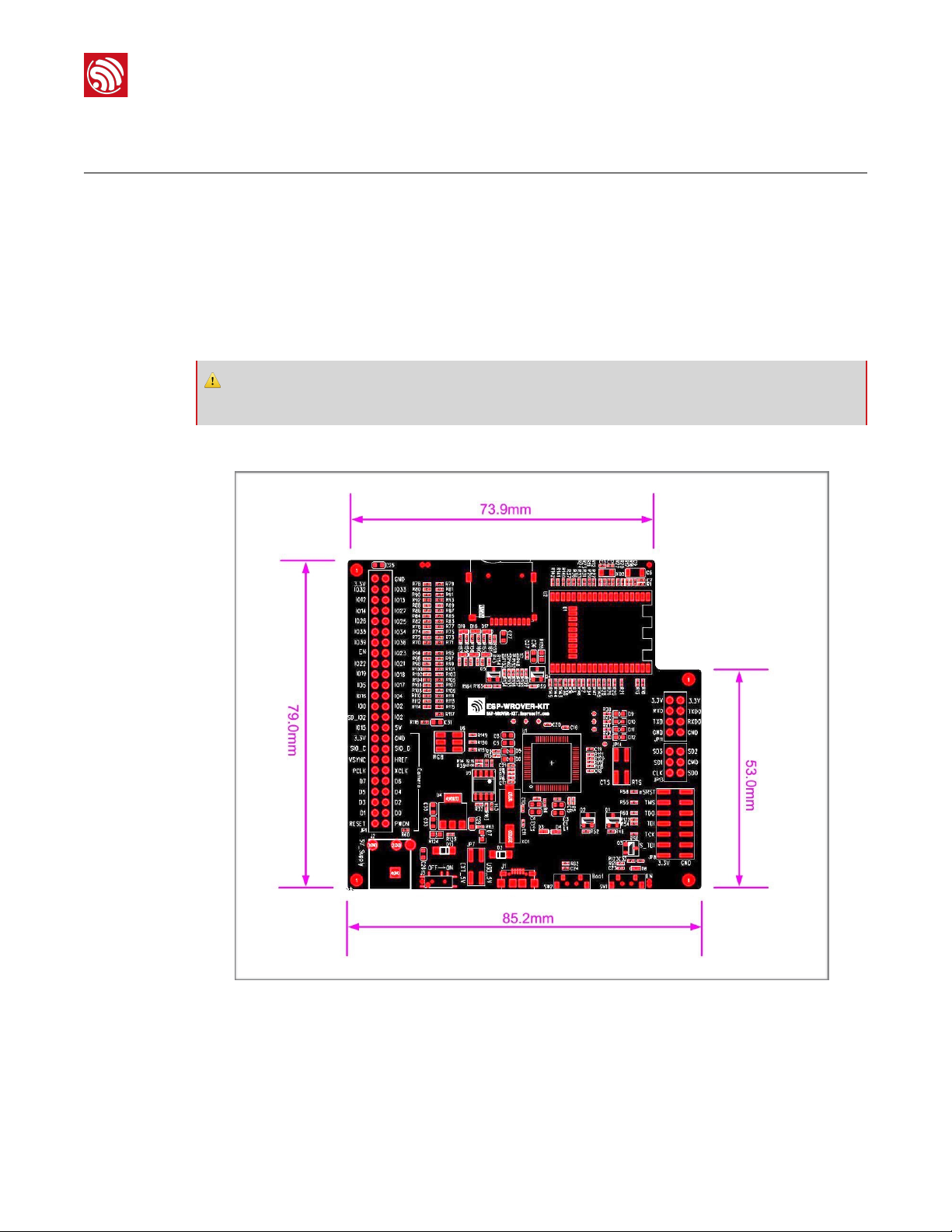
The ESP-WROVER-KIT dimensions are shown in the figure below.
!
Figure 1-1. The ESP-WROVER-KIT Dimensions
⚠ Notice:
ESP-WROVER-KIT integrates the ESP-WROOM-32 module by default.
Espressif
! /151
2017.01
Page 5
!
2. Block Diagram and PCB Layout
2. Block Diagram and PCB
Layout
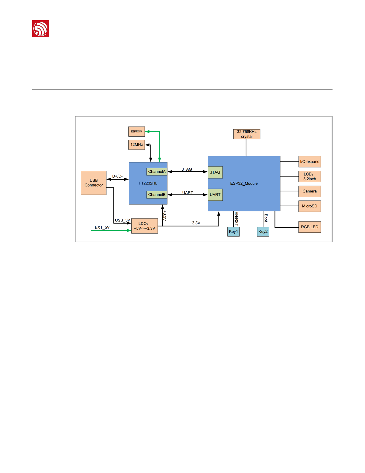
2.1.
Block Diagram
!
Figure 2-1. The ESP-WROVER-KIT Block Diagram
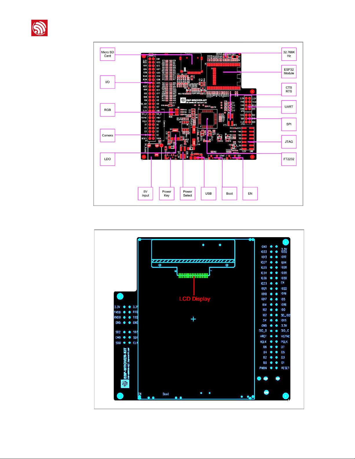
2.2.
PCB Layout
The layouts of the front and back sides of the ESP-WROVER-KIT are shown in Figures 2-2
and 2-3 respectively.
Espressif
! /152
2017.01
Page 6
!
2. Block Diagram and PCB Layout
!
Figure 2-2. The Layout of the Front Side
Figure 2-3. The Layout of the Back Side!
Espressif
! /153
2017.01
Page 7

!
3. Functional Description
3. Functional Description
Table 3-1 provides the functional description of the modules/interfaces that are featured on
the ESP-WROVER-KIT.
Table 3-1. ESP-WROVER-KIT Functional Description
Interface/Module
Description
32.768 KHz
An external precision 32.768 KHz crystal oscillator provides the chip with a clock of
low-power consumption during the Deep-sleep mode.
ESP32 Module
ESP-WROVER-KIT is compatible with both ESP-WROOM-32 and ESP32-WROVER.
The ESP32-WROVER module features all the functions of ESP-WROOM-32 and
integrates an external 32-MBit PSRAM for flexible extended storage and data
processing capabilities.
⚠ Note:
GPIO16 and GPIO17 are used as the CS and clock signal for PSRAM. To ensure
reliable performance, the two GPIOs are not led out.
CTS/RTS
Serial port flow control signal: the pin is not connected to the circuitry by default. To
enable it, JP14 must be shorted by a jumper.
UART
Serial port: the serial signals on FT2232HL and ESP32 are led to the two sides of
JP11. By default, the two signals are connected by a jumper. To use the ESP32
module serial interface only, the jumper may be removed and the module can be
connected to another external serial device.
SPI
SPI interface: the SPI interface connects to an external flash (PSRAM). To interface
another SPI device, an extra CS signal is needed. If an ESP32-WROVER is being
used, please note that the electrical level on the flash and SRAM is 1.8V.
JTAG
JTAG interface: the JTAG signals on FT2232HL and ESP32 are led to the two sides
of JP8. By default, the two signals are disconnected. To enable JTAG, shorting
jumpers are required on the signals.
FT2232
FT2232 chip is a multi-protocol USB-to-serial bridge. The FT2232 chip features USBto-UART and USB-to-JTAG functionalities. Users can control and program the
FT2232 chip through the USB interface to establish communication with ESP32.
The embedded FT2232 chip is one of the distinguishing features of the ESPWROVER-KIT. It enhances users’ convenience in terms of application development
and debugging. In addition, uses do not need to buy a JTAG debugger separately,
which reduces the development cost. The schematics are shown in Figure 3-1.
EN
Reset button: pressing this button resets the system.
Boot
Boot button: holding down the Boot button and pressing the EN button initiates the
firmware download mode. Then users can download firmware through the serial port.
USB
USB interface. It functions as the power supply for the board and the communication
interface between PC and ESP32 module.
Espressif
! /154
2017.01
Page 8

!
3. Functional Description
!
Figure 3-1. FT2232 Schematics
Power Select
Power supply selection interface: the ESP-WROVER-KIT can be powered through the
USB interface or the 5V Input interface. The user can select the power supply with
shorting jumpers. More details can be found in Chapter 4.
Power Key
Power on/off button: toggling to the right powers the board on; toggling to the left
powers the board off.
5V Input
The 5V power supply interface is used as a backup power supply in case of full-load
operation.
LDO
NCP1117(1A). 5V-to-3.3V LDO. (There is an alternative pin-compatible LDO —
LM317DCY, with an output current of up to 1.5A). NCP1117 can provide a maximum
current of 1A. The LDO solutions are available with both fixed output voltage and
variable output voltage. The relevant schematics are shown in Figure 3-2.
Camera
Camera interface: a standard OV7670 camera module is supported.
RGB
Red, green and blue (RGB) light emitting diodes (LEDs) are controlled by pulse width
modulation (PWM).
I/O
All the pins on the ESP32 module are led out to the pin headers on the ESPWROVER-KIT. Users can program ESP32 to enable multiple functions such as PWM,
ADC, DAC, I2C, I2S, SPI, etc.
Micro SD Card
Micro SD card slot for data storage: when ESP32 enters the download mode, GPIO2
cannot be held high. However, a pull-up resistor is required on GPIO2 to enable the
Micro SD Card. By default, GPIO2 and the pull-up resistor R153 are disconnected. To
enable the SD Card, use shorting jumpers on JP1 as shown in Figure 3-3.
LCD
ESP-WROVER-KIT supports mounting and interfacing a 3.2” SPI (standard 4-wire
Serial Peripheral Interface) LCD, as shown in Figure 2-3.
Interface/Module
Description
Espressif
! /155
2017.01
Page 9

!
3. Functional Description
!
Figure 3-2. LDO Schematics
!
Figure 3-3. Shorting Jumpers on JP1
Espressif
! /156
2017.01
Page 10

!
4. Basic Operation
4. Basic Operation
Before powering up the ESP-WROVER-KIT, please make sure that the board has been
received in good condition with no obvious signs of damage on it.
1.
If using the USB power supply, please use shorting jumpers on JP7 (Power Select), as
shown:
!
-
If using the 5V Input power supply, please use shorting jumpers on JP7, as shown:
!
2.
To enable UART communication, please use shorting jumpers on JP11, as shown:
!
Espressif
! /157
2017.01
Page 11

!
4. Basic Operation
After completing the two steps mentioned above, users can connect the board to a PC
through a USB cable. Configure the serial debugging tool with 115200-8-N-1 in the
settings, as shown in the screenshot below:
!
On successful power-up of the ESP32, a log similar to this will be printed on the serial
terminal:
!
Espressif
! /158
2017.01
Page 12

!
4. Basic Operation
•
To enable the flow control function, please use shorting jumpers on JP14 (CTS/RTS), as
shown:
!
•
To enable the JTAG function, please use shorting jumpers on JP8 (JTAG), as shown:
!
Espressif
! /159
2017.01
Page 13

!
5. Compilation and Download
5. Compilation and Download
We are using ESP-IDF as an example to show how to download firmware to the ESPWROVER-KIT.
5.1.
Getting ESP-IDF
Download ESP-IDF at: https://github.com/espressif/esp-idf/releases.
5.2.
ESP-IDF Directory Structure
The following figure shows the directory structure of ESP-IDF, including components,
examples, make, tools and docs. The components folder contains the core components
of ESP-IDF; the examples folder contains the program examples of ESP-IDF; the make
folder contains makefiles for ESP-IDF; the tools folder is the toolkit; the docs folder
contains ESP-IDF-relevant documentation.
!
Espressif
! /1510
2017.01
Page 14

!
5. Compilation and Download
5.3.
The hello_world Example
The esp-idf/examples/01_hello_world directory contains a sample code that can be run
on the ESP32.
1.
Using the command terminal, change the current directory to example/01_hello_world:
cdexamples/01_hello_world/
2.
Configure IDF_PATH:
exportIDF_PATH=/home/share/esp-idf-driver/esp-idf
3.
Check the IDF_PATH configuration to make sure it is properly set. Failing to set the path
will cause failure to the linking of dependent files later.
echo$IDF_PATH
4.
Compile the program to generate BIN files. These BIN files have to be downloaded to
the ESP-WROVER-KIT. Please see Sections 5.3.1 and 5.3.2 for detailed instructions.
5.3.1.
Using the ESP32 DOWNLOAD TOOL
Execute the following command in the terminal to make the example project and generate
executable BIN files:
make
Three BIN files need to be downloaded: example/01_hello_world/bootloader/
bootloader.bin, example/01_hello_world/partitions_singleapp.bin and example/
01_hello_world/hello-world.bin. Then, users can flash these BIN files by using the ESP32
DOWNLOAD TOOL. Please follow the steps below:
1.
Open the ESP32 DOWNLOAD TOOL.
2.
Configure the download tool and click on “START“, as shown below:
📖 Note:
Please download the FLASH DOWNLOAD TOOL at:"
http://espressif.com/en/support/download/other-tools?keys=&field_type_tid%5B%5D=13.
⚠ Notice:
Most computers will automatically reset the ESP32 into download mode when you start uploading. If this
does not work on your computer, try holding down the Boot button (and possibly pressing and releasing the
EN button) when starting the upload.
Espressif
! /1511
2017.01
Page 15

!
5. Compilation and Download
!
3.
Open the serial port. Set the Port, Baud rate = 115200, Data bits = 8, and Stop bits = 1.
If the log below is printed, then it shows that the firmware has been downloaded to the
ESP-WROVER-KIT successfully.
!
Espressif
! /1512
2017.01
Page 16

!
5. Compilation and Download
5.3.2.
Using esptool
Users need to configure the serial port before compiling and downloading BIN files. Serial
port configuration is not required if the Flash Download Tool is used to flash the BIN files on
to the ESP-WROVER-KIT. However, other important system parameters may be set via
menuconfig. Please complete this step before generating BIN files.
1.
Enter makemenuconfig:
makemenuconfig
Then, the following interface is displayed:
!
2.
Select Serial flasher config to configure the serial port, as shown below:
!
3.
Configure the serial port, as shown below:
Espressif
! /1513
2017.01
Page 17

!
5. Compilation and Download
!
4.
Click “OK” and exit makemenuconfig.
5.
Flash BIN files directly via the command line below:
makeflash
📖 Note:
For more information on ESP-IDF, please see ESP-IDF Getting Started Guide.
Espressif
! /1514
2017.01
Page 18

Disclaimer and Copyright Notice
Information in this document, including URL references, is subject to change without
notice.
THIS DOCUMENT IS PROVIDED AS IS WITH NO WARRANTIES WHATSOEVER,
INCLUDING ANY WARRANTY OF MERCHANTABILITY, NON-INFRINGEMENT, FITNESS
FOR ANY PARTICULAR PURPOSE, OR ANY WARRANTY OTHERWISE ARISING OUT
OF ANY PROPOSAL, SPECIFICATION OR SAMPLE.
All liability, including liability for infringement of any proprietary rights, relating to the use of
information in this document, is disclaimed. No licenses express or implied, by estoppel or
otherwise, to any intellectual property rights are granted herein.
The Wi-Fi Alliance Member logo is a trademark of the Wi-Fi Alliance. The Bluetooth logo is
a registered trademark of Bluetooth SIG.
All trade names, trademarks and registered trademarks mentioned in this document are
property of their respective owners, and are hereby acknowledged.
Copyright © 2016 Espressif Inc. All rights reserved.
Espressif IOT Team"
www.espressif.com
 Loading...