

Page 1

With Brushless Motor and
4-Bladed Prop
ASSEMBLY INSTRUCTIONS
SPECIFICATIONS:
Wingspan: 54 in. (1380mm)
Length: 36 in. (920mm)
Weight (inc. battery): 24 oz. (690g)
Page 2
2 Phoenix Instruction Manual
Vital safety info
CAUTION! The Phoenix is not a toy.
It can cause injury to persons/animals and/or property
if not used correctly. It is unsuitable for persons under
the age of 14. You should take care and observe the
principles of safety when flying this model. In the UK,
we recommend you observe the British Model Flying
Association (BMFA) safety code at all times, which can
be found at the following address: http://www.bfma.org.
YOU ASSUME ALL RISK.
Before beginning construction, please read this
document thoroughly and familiarize yourself with the
construction sequence of the Phoenix. If any information
in this manual is unclear, please contact your supplier
for help. After reading this manual store it in a safe
place for future reference. This kit is a beginnerintermediate model, basic RC flying knowledge and
skills are required.
about the flying area
required
If you are a newcomer to R/C flight and have never flown
a radio control model before; it is vital you seek advice
from an experienced model pilot on where and how to fly.
Only fly in large open spaces that are approved for R/C
model flying and that are away from people, animals,
buildings, power lines, water or trees.
Only fly in bright sunny conditions where wind speed does
not exceed 5mph.
training, crashes & spares
The Phoenix has been designed to be strong and very
easy to repair, however, it is not invulnerable and most
people will break parts during their flying career. This is
quite normal. All parts are available as spares from your
supplier. Crash damage is not covered by warranty.
important notice
This manual is supplied with all versions of the Phoenix.
Please note that any reference in this manaul to the
Transmitter, Receiver, Charger and Power supply are not
applicable to the Phoenix version supplied without TX/RX,
Charger and Power supply.
contents
weee disposal .................................................................. 2
Vital safety info ............................................................... 2
About the flying area required ...................................... 2
Training, crashes & spares ............................................ 2
important notice............................................................... 2
Guarantee/warranty ........................................................ 2
Kit contents ....................................................................... 3
Lithium polymer battery safety ..................................... 4
Lithium polymer flight battery ....................................... 4
Charging the flight battery ......................................... 5
Assembling the Phoenix ................................................ 6
Assembling the propeller ............................................ 10
Switch on the transmitter ............................................ 11
Transmitter layout .......................................................... 12
Mode II transmitter layout ....................................... 12
Mode I transmitter layout ......................................... 12
Pairing the esc and transmitter .................................. 12
Control checks ............................................................... 13
Preflight checks ............................................................. 15
Flying................................................................................ 15
Take-off ........................................................................ 15
Landing ........................................................................ 15
Model Engines’ warranty information ....................... 16
guarantee/warranty
J. Perkins Distribution Ltd guarantee this product to be free of manufacturing and assembly defects for a period of one year from
time of purchase. This does not affect your statutory rights. This warranty is not valid for any damage or subsequent damage
arising as a result of a crash, misuse, modification or for damage or consequential damage arising as a result of failure to observe
the procedures outlined in this manual. Operation of this model is carried out entirely at the risk of the operator. Please note that,
whilst every effort is made to ensure the accuracy of instructions and material included with this product, mistakes can occur and
neither J. Perkins Distribution Ltd. nor it’s distributors will be held liable for any loss or damage arising from the use of this model
or for any loss or damage arising from omissions or inaccuracies in the associated instructions or materials included with this
product.
We reserve the right to modify the design of this product, contents and manuals without prior notification.
© 2012 J Perkins Distribution Ltd, Lenham, Kent, UK ME17 2DL. www.jperkinsdistribution.co.uk
All rights reserved. E&OE.
weee disposal
Do not dispose of this product with other household
waste. Instead, it is your responsibility to dispose of
your waste equipment by handing it over to a designated
collection point for the recycling of waste electrical
and electronic equipment. The separate collection and
recycling of your waste equipment at the time of disposal
will help to conserve natural resources and ensure that
it is recycled in a manner that protects human health
and the environment. For more information about where
you can drop off your waste equipment for recycling,
please contact your local council, your household waste
disposal service or the shop where you purchased the
product.
Page 3
3Phoenix Instruction Manual
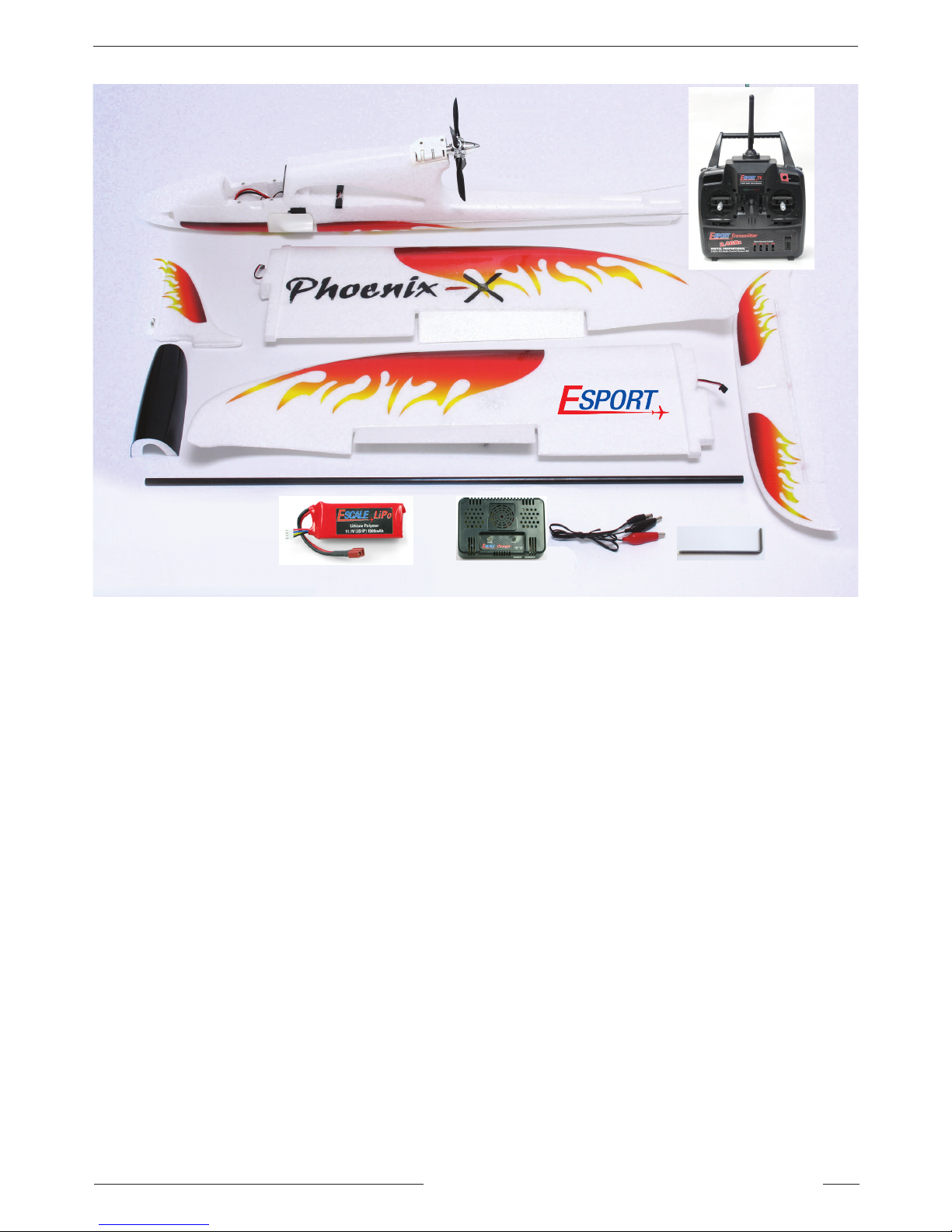
Kit contents
CONTENTS LIST
2.4 GHz Transmitter and Receiver (Only included in RTF complete set)
Fuselage
Main Wing w/Carbon Fibre Spar
Horizontal Tail
Fin and Rudder
Outrunner Brushless Motor 1050Kv (pre-installed)
20A ESC (pre-installed)
3-Cell 11.1V 1500mAh Li-poly Battery
Li-poly Balance Charger for 2-3 Cells, with leads to connect to 12V DC Power Source.
4-9 gram Servos (pre-installed)
4-Bladed Propeller
Wrench / Hex Key
ADDITIONAL ITEMS REQUIRED
4 x AA Transmitter batteries
5-minute Epoxy Glue
Small Phillips screwdriver
Hobby Knife
NB. If purchasing the RTF version excluding TX/RX/Charger/Power supply you will need to purchase these
separately
Page 4
4 Phoenix Instruction Manual
lithium polymer battery safety
BEFORE CHARGING LI-PO’S
Before charging your battery check for any damage e.g. check if the battery has expanded or swollen in size
or if the battery cells have been punctured. If any of the above is true: DO NOT CHARGE THE BATTERY!
CHARGING LI-PO’S
Only use a charger designed to charge Lithium polymer batteries. Never use a nicad or other charger as this
is very dangerous.
Never attempt to charge at a rate faster than that recommended in the instructions. Check that the battery cell
count matches the charger cell count switch (if fitted).
Never charge unattended. Always stay with your battery whilst charging in case of overheating or fire.
Charge on a safe surface or container (e.g. old unused microwave oven). Charge only on non-flammable
surfaces, e.g. concrete floor preferably outdoors, or in a pyrex cooking dish with the battery placed on a bed
of sand, or in a fireplace. Never charge inside a car!
Switch off charger if battery gets too hot. If the battery becomes hot to the touch during charging, disconnect
and switch off immediately.
Extinguish fires with sand. If something goes wrong and your battery catches fire, always have sand from a
fire bucket at hand to douse the flames. Do NOT use water!
USING LI-PO’S
Do not modify/change any part of the battery or lead. Do not remove its heat shrink protective covering.
Removal or modification may damage the battery and will invalidate any warranty claim.
Do not place this battery near fires or anything with high temperatures.
Do not charge batteries while you are driving and do not store batteries in any type of motor vehicle.
Do not let the battery get wet or become submerged in any type of liquid.
Do not carry loose batteries in your pocket or bag as they could short-circuit against other items.
If you should get electrolyte from the cells on your skin, wash thoroughly with soap and water. If in your eyes,
rinse thoroughly with water. Seek medical assistance.
lithium polymer flight battery
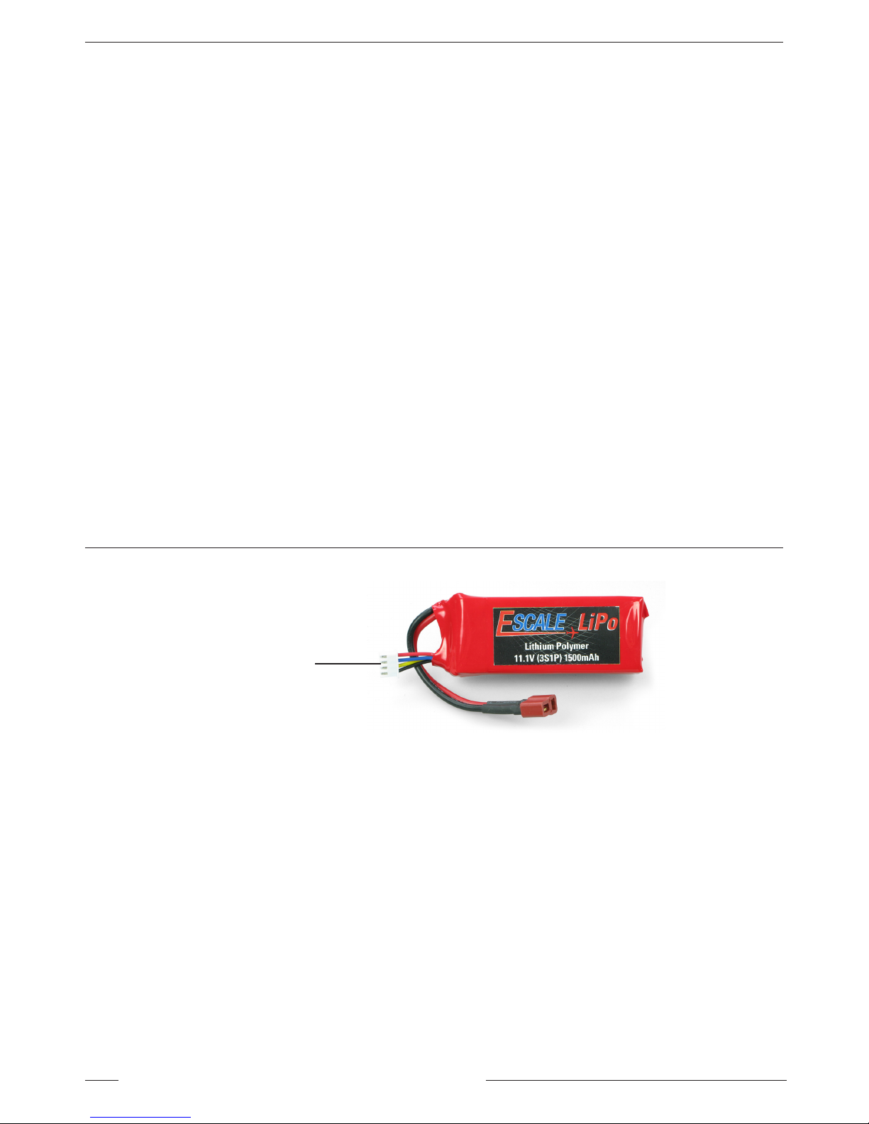
Charging lead only
The LiPo flight battery is a high power battery designed to give a flight time of approximately 10mins per charge. It is
supplied in a partially charged state.
As well as a red deans style conector lead (for connection to the ESC) the battery is also fitted with a white 3-pin
polarised connector. This is the charge lead. Connect this white plug to the 12V charger. Always leave the battery in
a partially charged state. Never leave it in a discharged state.
The battery should be charged if you notice the model losing power. At this point land and recharge the battery.
Do not be tempted to run the battery past this stage as you will be over-discharging and the battery may be damaged.
WARNING!
We recommend that you use only the supplied EScale charger with this battery.
WARNING!
Over-discharging will shorten the life of the battery or destroy it. Stop flying immediately you notice the model is
losing power and recharge the battery.
WARNING!
Do not short circuit—battery may explode!
IF YOU HAVE NOT DONE SO ALREADY PLEASE READ THE LITHIUM POLYMER BATTERY SAFETY INSTRUCTIONS
ABOVE BEFORE PROCEEDING ANY FURTHER.
Page 5
5Phoenix Instruction Manual
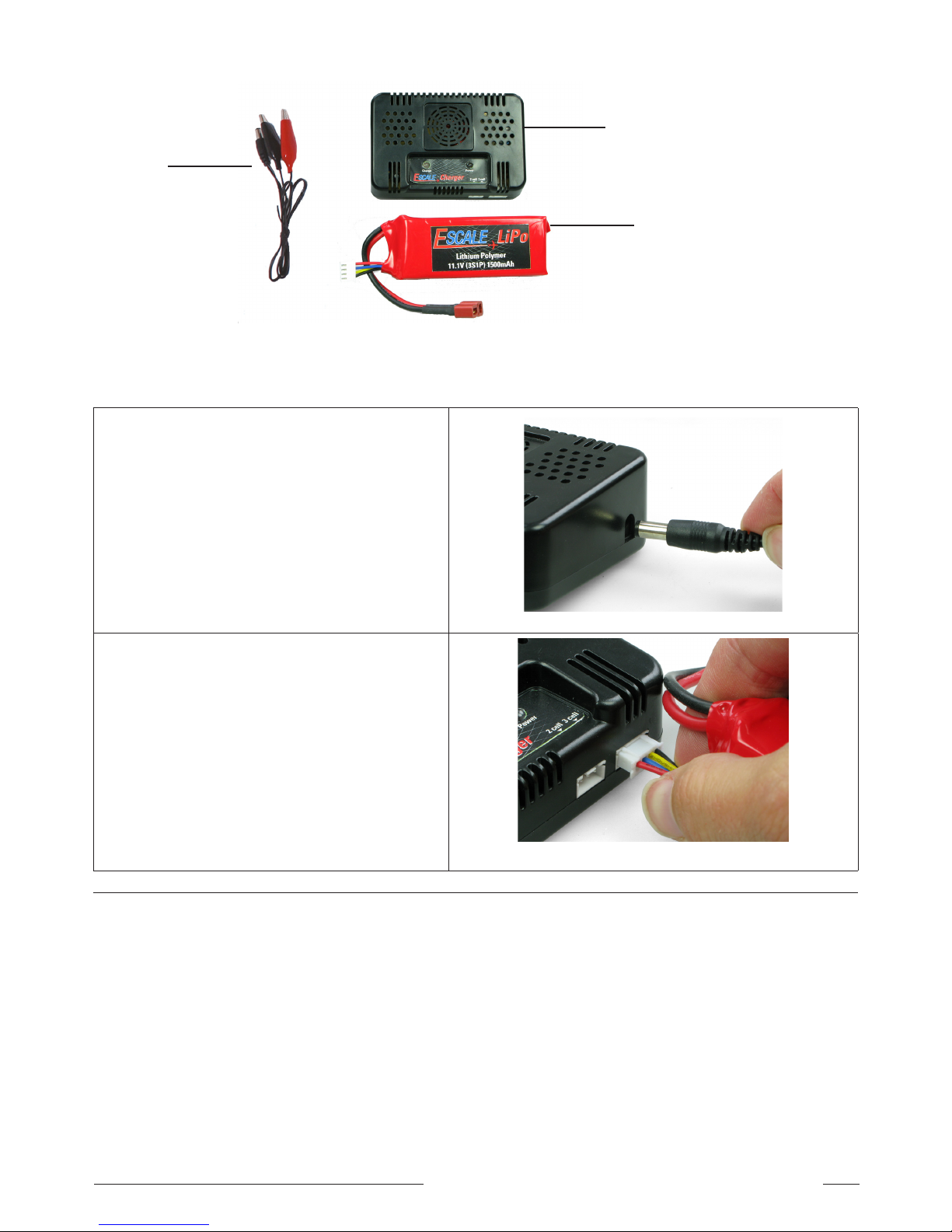
CHARGING THE FLIGHT BATTERY
12V DC LiPo Charger
for 2-3 Cell LiPo Cells
LiPo Battery
The charger is designed to automatically charge the LiPo battery in about an hour from a discharged state. Using the
DC Leads provided, the 12V DC automatic charger needs to be powered by 12V DC power supply. You can use a 12V
sealed modelling battery to power the DC automatic charger, available separately.
1. Connect the charger to the power source.
The power LED will light Red and the charge
LED will light Green.
2. Plug the white 3-pin connector on your Li-po
battery into the 3pin socket in the front of the
charger.
Charging: Charge LED flashes Red.
Fully charged: Charge LED is solid Green.
If the charge LED is solid Red when you plug in the
battery no charge is needed.
3. When the battery is fully charged disconnect
the battery from the charger. Disconnect the
12V power source from the charger. Your Lipo is ready for use.
DC Leads
Page 6
6 Phoenix Instruction Manual
assembling the phoenix
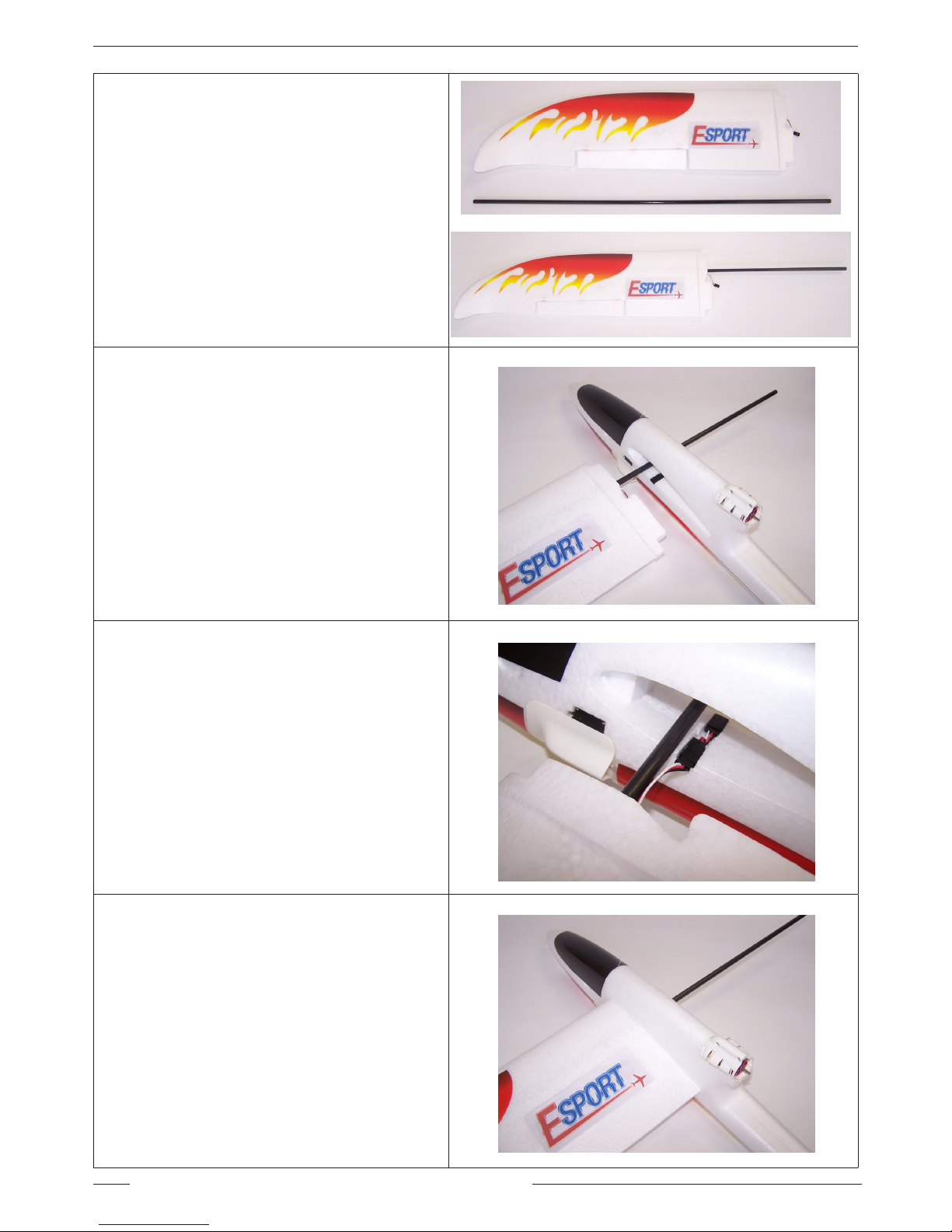
1. Locate the carbon fibre spar and left hand
wing panel.
2. Gently push the carbon fibre spar into the
left hand main wing panel until it is fully
inserted.
3. Insert the other end of the carbon fibre spar
into the wing opening of the fuselage.
4. Leave enough room to connect the servo plug
for the left hand aileron servo into the socket
on the left hand side of the fuselage.
5. Check the black wire of the plug lines up
with the black wire of the socket.
6. Now push the wing all the way into the
fuselage.
Page 7
7Phoenix Instruction Manual
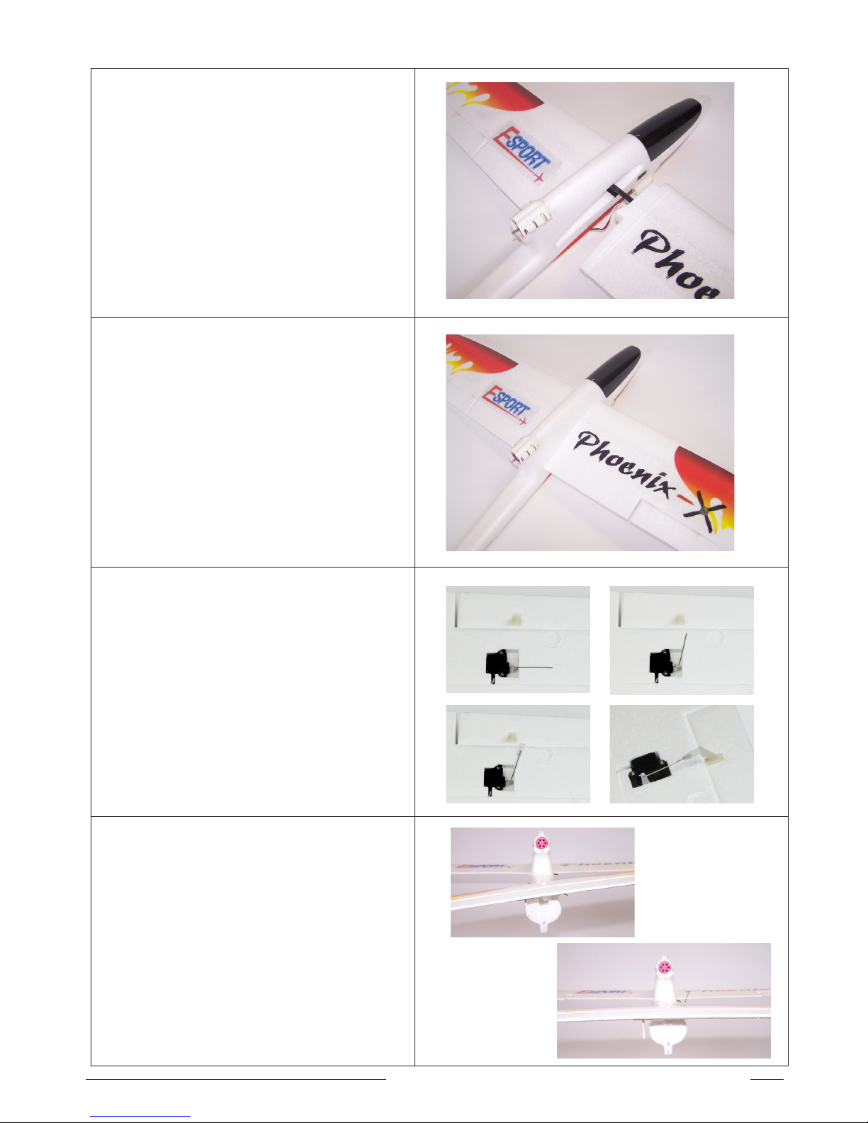
7. Locate the right hand wing panel and slide it
on the right hand end of the carbon fibre spar.
8. Leave enough room to connect the servo
plug for the right hand aileron servo into the
socket on the right hand side of the fuselage.
Check the black wire of the plug lines up
with the black wire of the socket.
9. Now push the wing all the way into the
fuselage
10. Insert the z-bent end of aileron pushrod wire
into the servo arm of each aileron servo.
Use the outermost hole on the servo arm.
Attach the clevis to the straight end of the
pushrod wire and clip it to the servo horn.
Note: Do not tighten the grub screw with the
wrench/hex key just yet. You may need to
adjust this later to ensure a neutral setting
for the elevator once the transmitter and
plane are turned on.
11. Dry fit the horizontal tail to confirm a good
fit and ensure it will line up with the wing
when glued in position.
If the horizontal tail does not line up, now is
the time to remove a small amount of foam
from the high side of the fuselage.
Dry fit again to confirm correct alignment.
WRONG
RIGHT
Page 8
8 Phoenix Instruction Manual
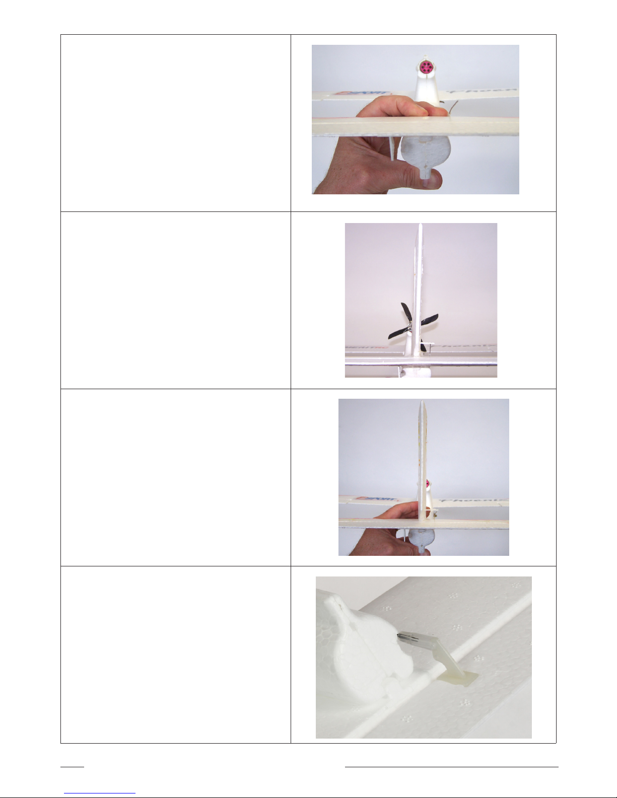
12. Use 5 minute epoxy glue (available
separately), and press the horizontal tail into
position and hold for at least 5 minutes to
ensure a good bond.
Note: We recommend that you use 5 minute epoxy
to glue the horizontal tail and vertical fin as
this will provide a more permanent fixing.
13. Dry fit the vertical fin to confirm a good fit.
Note: Check the vertical fin will be epoxied at 90
degrees to the horizontal tail.
14. Epoxy the vertical fin to the fuselage and
horizontal tail.
Hold in place for at least 5 minutes to ensure
a good bond.
Note: Re-check while the epoxy is setting that the
vertical fin is at 90 degrees to the horizontal
tail.
15. Clip the elevator pushrod clevis onto the
servo horn.
Note: You may need to adjust this later to ensure
a neutral setting for the elevator once the
transmitter and the Phoenix are turned on.
Page 9
9Phoenix Instruction Manual
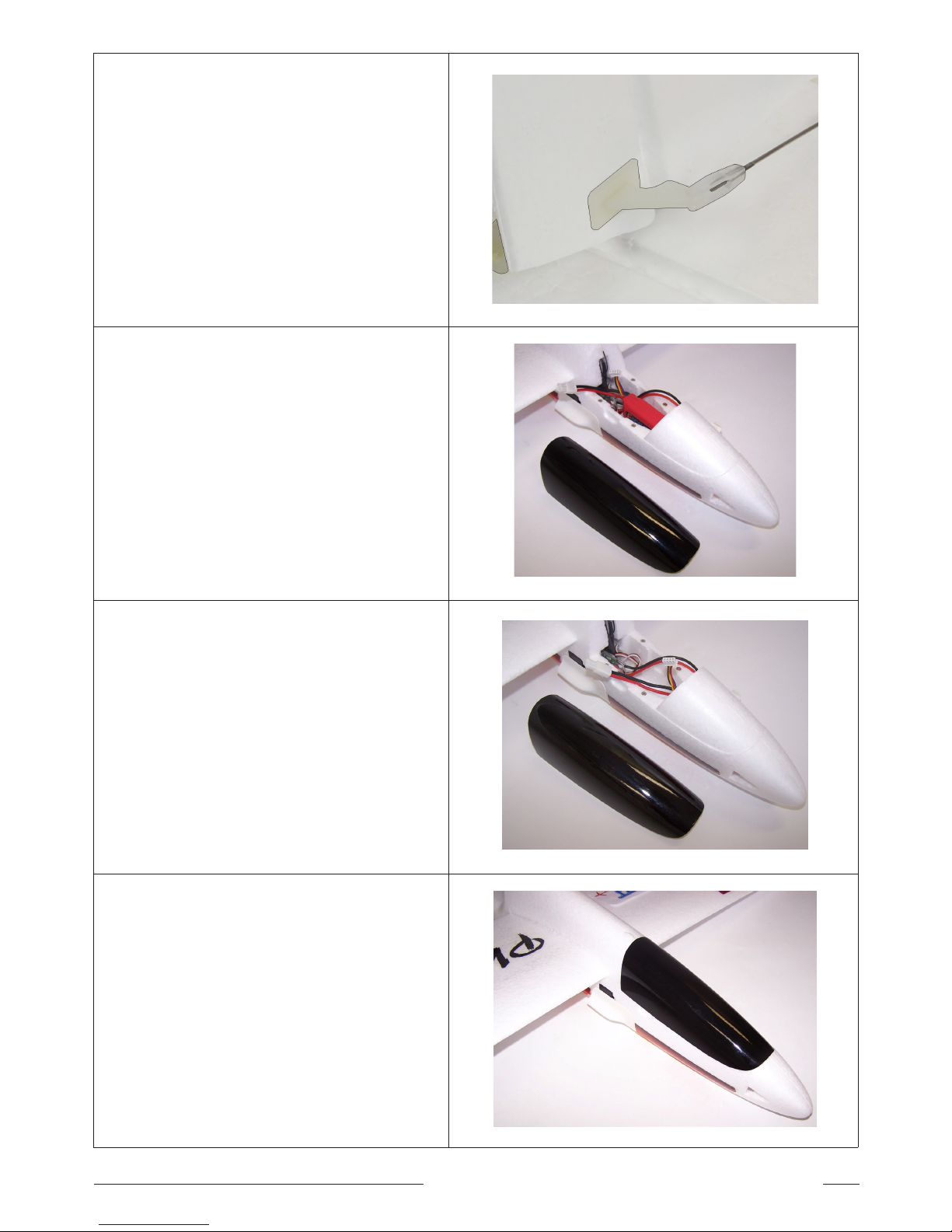
16. Clip the clevis onto the servo horn.
Note: You may need to adjust this later to ensure
a neutral setting for the elevator once the
transmitter and the Phoenix are turned on.
17. The flight battery slides in place in the
hollow compartment in the nose of the
fuselage. Push the battery all the way
forward so it is held securely by the sides of
the fuselage.
Tip: Velcro (purchased separately) may also be
used to secure the battery in position.
Note: It is important to secure the battery. If the
battery moves, it can change the centre of
gravity, which will make the plane difficult
to control
18. Before each flight, make sure the battery is
secure.
19. Re-attach the canopy. The canopy is held
securely in place with strong magnets.
Page 10
10 Phoenix Instruction Manual
assembling the propeller
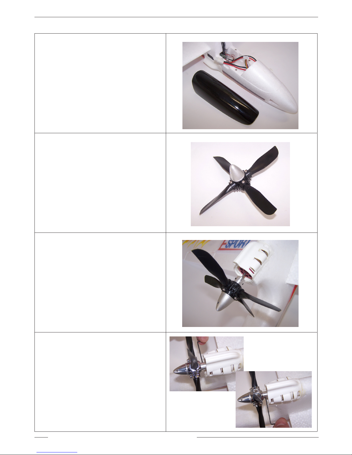
20. For safety, always ensure the flight battery is
disconnected before attaching the propeller.
21. Locate the four blade propeller.
22. Install the propeller on the motor shaft.
Note: Locate the grub screws over the flat spot on
the motor shaft. The flat spots help secure
the propeller and prevent it falling off in
flight.
23. Tighten the grub screws on either side of the
spinner with your wrench/hex key.
Page 11
11Phoenix Instruction Manual
The Escale transmitter is only included in the RTF
complete set. If you are using your own transmitter
please follow the instructions for that transmitter.
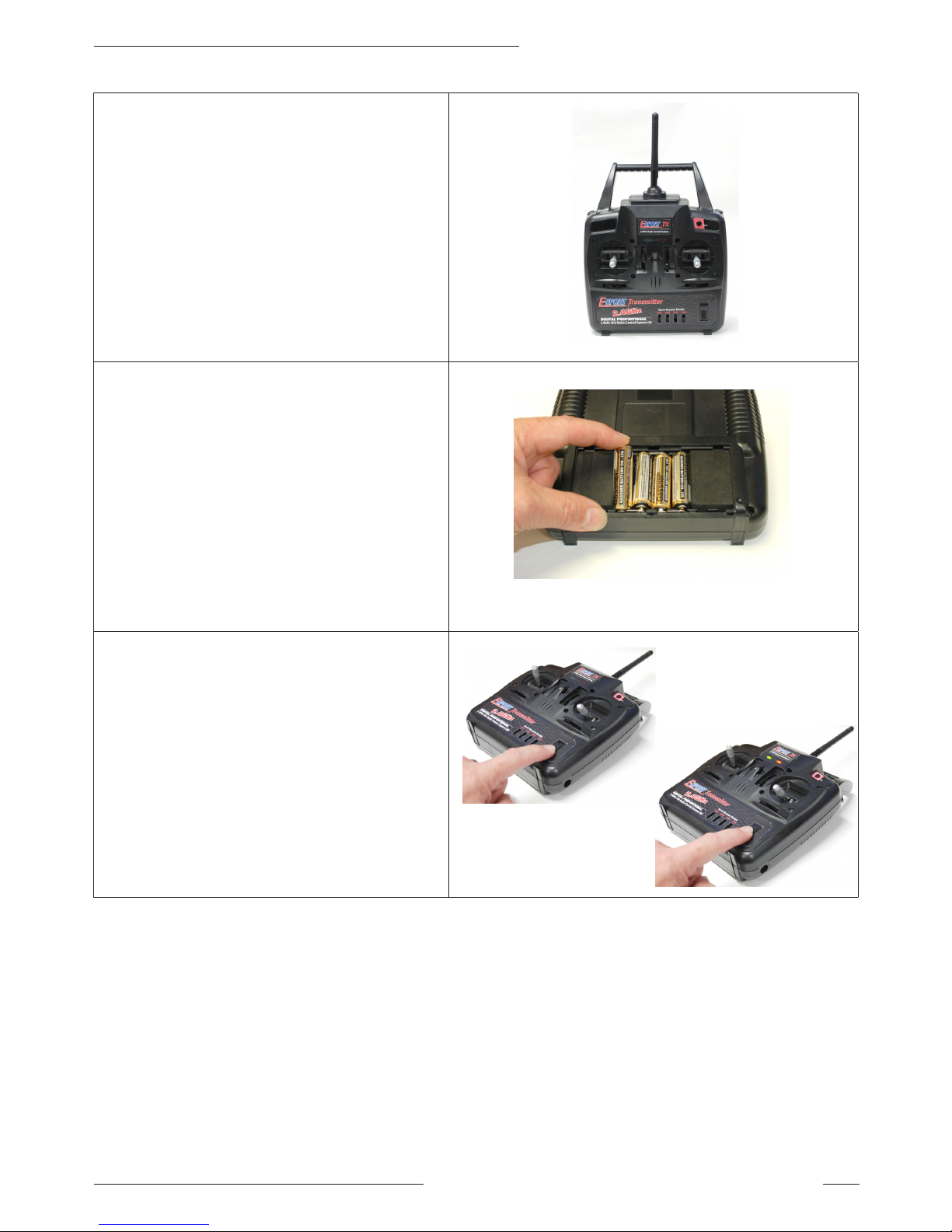
24. Locate 2.4GHz. Transmitter.
25. Install 4-AA batteries (sold separately) into
the battery compartment located in back of
Transmitter case.
26. Turn on the transmitter by pushing the ON/
OFF sliding switch forward..
Note: Always turn your transmitter ON before you
turn your plane on.
Note: Always turn your plane OFF before you turn
your transmitter OFF.
Note: Ensure the throttle stick and trim slider
are in the down position (mode 1 shown).
The other trim sliders should all be centered
as shown.
switch on the transmitter
Page 12
12 Phoenix Instruction Manual
27. After turning ON the transmitter as shown
above, plug in the battery to turn on the
Phoenix.
Note: Always turn your transmitter ON before you
turn your plane on.
Note: Always turn your plane OFF before you turn
your transmitter OFF.
transmitter layout
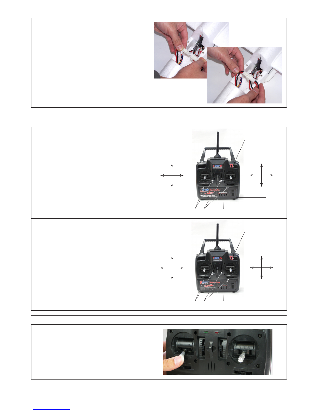
MODE II TRANSMITTER LAYOUT
28. Left Stick is Throttle (up and down) and
Rudder (side to side)
29. Right Stick is Elevator (up and down) and
Ailerons (side to side).
30. PDM switch is on the Top Right front. It is
used for pairing (also known as binding) the
transmitter to the receiver.
31. Servo reversing switches across lower front
of case.
32. Fine trim adjustments for 4 main channels.
Please see the EScale Transmitter Manual for more
detailed instructions on Transmitter functions
Throttle High
Throttle Low
Rudder
Right
Rudder
Left
Elevator Down
Elevator Up
Aileron
Right
Aileron
Left
Trim Adjustments
Servo reverse switches
Power
Switch
‘PDM’ Switch
MODE I TRANSMITTER LAYOUT
33. Left Stick is Elevator (up and down) and
Rudder (side to side)
34. Right Stick is Throttle (up and down) and
Ailerons (side to side).
35. PDM switch is on the Top Right front. It is
used for pairing (also known as binding) the
transmitter to the receiver.
36. Servo reversing switches across lower front
of case.
37. Fine trim adjustments for 4 main channels.
Please see the EScale Transmitter Manual for more
detailed instructions on Transmitter functions
Elevator Down
Elevator Up
Rudder
Right
Rudder
Left
Throttle Up
Throttle Down
Aileron
Right
Aileron
Left
Trim Adjustments
Servo reverse switches
Power
Switch
‘PDM’ Switch
pairing the esc and transmitter
38. PLEASE NOTE: The first time that the model
is powered up the ESC must recognize the
transmitter and verify the range of throttle
motion. Follow these easy steps.
39. With the throttle stick at its lowest position,
turn on the transmitter and then plug the
flight battery into the ESC.
Note: Photo shows a mode II transmitter
Page 13
13Phoenix Instruction Manual
40. After a few seconds there will be a beep
tone, move the throttle stick to full throttle,
there will be another beep tone but the motor
will not start.
41. Return the stick to its lowest position for
the final confirmation tones after which the
throttle will work normally.
42. Please note that this process only needs to
be done one time. After this the throttle will
operate normally for all subsequent flights.
control checKs
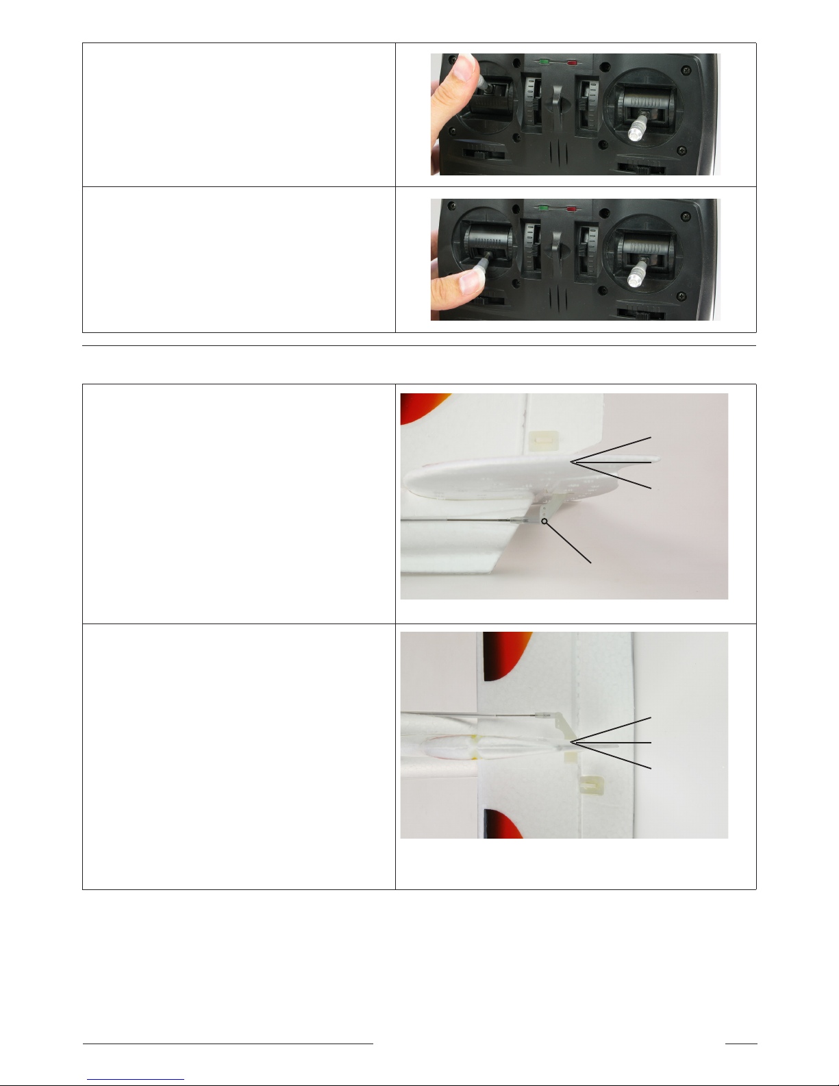
43. Elevator is controlled by the elevator stick.
Check that the direction and distance of
movement is correct.
44. Stick toward the bottom of the transmitter
the elevator should move up. When moved
toward the top of the transmitter the elevator
should move down.
45. Adjust the position of the pushrod to get
approx. 1/2” (13mm) in each direction.
Note: Ensure that the clevis is clipped securely
onto the servo horn so that it will not come
loose in flight.
46. Rudder is controlled by the rudder stick.
Check that the direction and distance of
movement is correct. Stick to the right,
rudder should move to the right and stick to
the left, rudder should move to the left.
47. If the direction is incorrect, switch the
servo-reversing switch on the front of the
transmitter.
48. Adjust the position of the pushrod to get
approx. 3/4” (19mm) movement in each
direction measured at the trailing edge.
Note: Ensure that the clevis is clipped securely
onto the servo horn so that it will not come
loose in flight.
1/2” (13mm)
3/4” (19mm)
1/2” (13mm)
3/4” (19mm)
Adjust the position of the
pushrod to get 1/2” in each
direction
Page 14
14 Phoenix Instruction Manual
49. Ailerons are controlled by the aileron stick.
Check that the direction and distance of
movement are correct.
50. If the direction is incorrect, switch the
servo reversing switch on the front of the
transmitter.
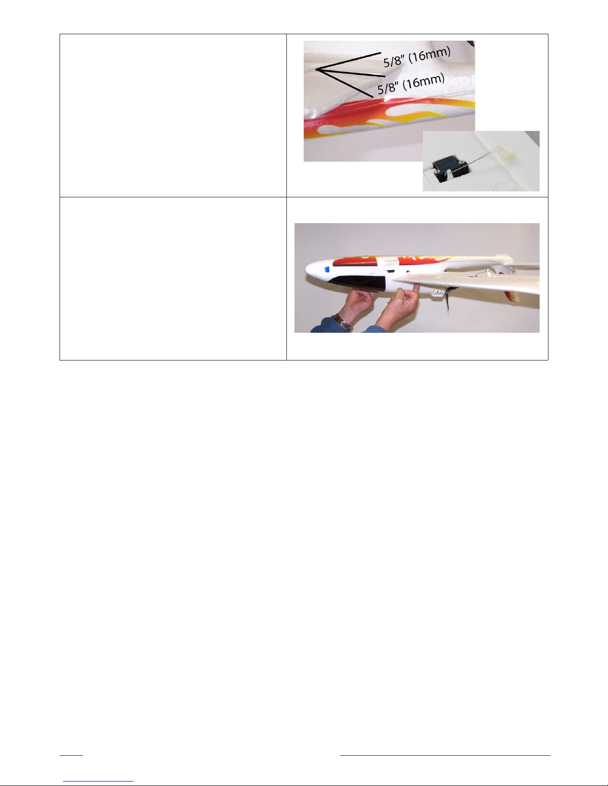
51. Adjust the position of the pushrod to get
approx. 5/8” (16mm) movement in each
direction measured at the trailing edge
Note: Ensure that the clevis is clipped securely
onto the servo horn so that it will not come
loose in flight.
52. The CG (Center of Gravity) for the Phoenix is
located 2-1/2” to 2-3/4” (65-70mm) behind the
leading edge of the main wing at the root of
the wing.
53. Check the CG location by balancing the
model upside down on your fingertips.
Note: The fuselage should be horizontal to the
ground when the model is balancing on your
fingertips at the correct CG.
Page 15
15Phoenix Instruction Manual
preflight checKs
If you are new to flying R/C aircraft, or even an experienced modeller, we recommend you have a fellow R/C modeller
help you with the first flight. Some items you will need to complete on your first preflight are:
1. Aircraft assembled correctly and ready for flight.
2. All control throws are set per this manual.
3. Transmitter battery power is good.
4. Aircraft balances at the recommended CG
5. Flight Battery is fully charged and secure.
6. All electronics are operating correctly, proper direction, and secure.
7. Wait for a calm or light wind day for first flights.
8. If you are new to R/C flying, consider having an accomplished flyer make the first flight and trim the aircraft.
flying
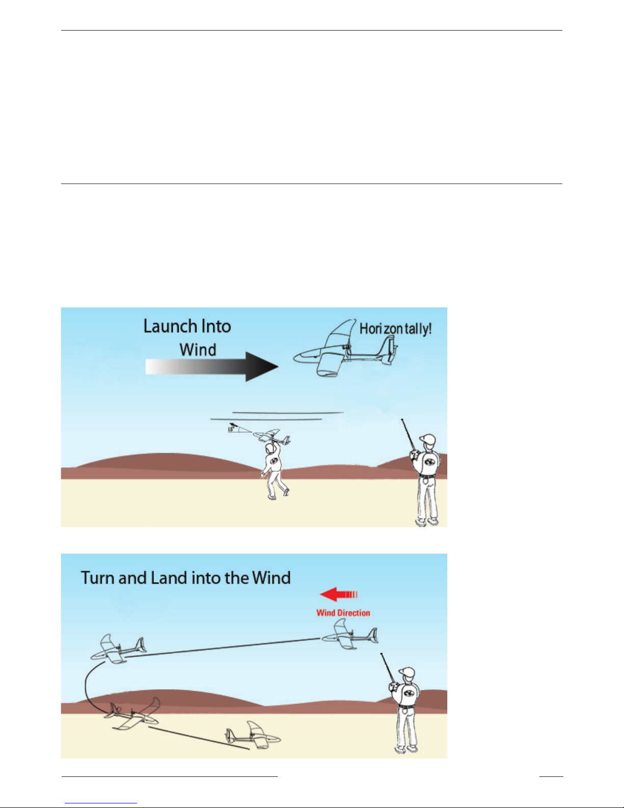
Ask another person to launch the Phoenix into the wind horizontally with the nose slightly up, but no more than 15
degrees. Smoothly advance the throttle. After a few feet apply a small amount of up elevator and the model will
begin to climb. Continue to climb out at a shallow angle until you reach an altitude of 75 to 100 feet and level off.
Adjust the flight surface trims until the model flies wings level without a tendency to climb or dive. When making
a landing approach a small amount of throttle should be maintained. When the throttle is completely off the large
4-bladed prop creates a great deal of drag which will cause the model to slow down quickly. We hope that you enjoy
your Phoenix as much as we do.
TAKE-OFF
LANDING
Page 16

06.12
European agents: J Perkins Distribution,
Lenham, England
www.jperkinsdistribution.co.uk
 Loading...