

Page 1

VITEK MD-1102
User Manual
Page 2

i
Contents
1 Introduction ........................................................................................................1
1.1 Application ............................................................................................. 1
1.2 Environment .......................................................................................... 1
1.3 System Requirements ...........................................................................2
1.4 Safety Precautions ................................................................................ 2
1.5 LED Status............................................................................................. 3
1.5.1 Front Panel ................................................................................. 3
1.5.2 Rear panel .................................................................................. 3
2 Hardware Installation .........................................................................................4
2.1 ADSL Connection of Router .................................................................. 4
2.2 USB Installation ..................................................................................... 5
3 Web Configuration Management .......................................................................6
3.1 Logging In to the Router ........................................................................ 6
3.2 Quick Setup – PPPoE ........................................................................... 7
3.3 DSL Router Device Information........................................................... 11
3.4 Advanced Setup .................................................................................. 12
3.4.1 WAN Configuration ................................................................... 12
3.4.2 LAN Configuration ....................................................................36
3.4.3 NAT........................................................................................... 41
3.4.4 Security.....................................................................................41
3.4.5 Quality of Service...................................................................... 49
3.4.6 Routing .....................................................................................53
3.4.7 DNS .......................................................................................... 55
3.4.8 DSL...........................................................................................56
3.5 Diagnostics .......................................................................................... 57
3.6 Management........................................................................................58
3.6.1 Setting....................................................................................... 58
3.6.2 System Log...............................................................................59
3.6.3 Internet Time............................................................................. 61
3.6.4 Access Control.......................................................................... 62
3.6.5 Update Software ....................................................................... 64
3.6.6 Save/Reboot ............................................................................. 65
4 Q&A.................................................................................................................. 65
Page 3

1
1 Introduction
The Router is a highly ADSL2+ integrated access device and can support ADSL
link downstream up to 24 Mbps and upstream up to 1 Mbps, which is designed to
provide a simple and cost-effective ADSL Internet connection for a private
Ethernet. The Router combines high-speed ADSL Internet connection. It is
usually preferred to provide high access performance applications for the
individual users, the SOHO, the small enterprise and so on.
The router is easy to install and use. The Router can be connected to an Ethernet
LAN or a computer via standard Ethernet ports. The ADSL connection is made by
using ordinary telephone line with standard connectors. Multiple workstations can
be connected to the Internet by using a single wide area network (WAN) interface
and a single global IP address. The advanced security enhancements, packet
filtering and port redirection is able to protect your network from potentially
devastating intrusions by malicious agents.
You can access the web-based management interface to realize network and
router management by using any web browser. You may also enable remote
management to enable configuration of the Router via the WAN interface.
1.1 Application
Home gateway
SOHOs
Small enterprises
Shared broadband internet access
Audio and video streaming and transfer
PC file and application sharing
Network and online gaming
1.2 Environment
Operating temperature: 0ºC~40 ºC (32ºF~104ºF)
Page 4

2
Storage temperature: -10 ºC ~55 ºC (14ºF~131ºF)
Operating humidity: 10%~95%, non-condensing
Storage humidity: 5%~95%, non-condensing
Power adapter input: 100 V—240 V AC, 50/60 Hz
Power adapter output: 12 V DC, 500 mA
1.3 System Requirements
Pentium 233 MHz or above
Memory: 64 MB or above
10M Base-T Ethernet or above
Windows 9x, Windows 2000, Windows XP, Windows ME, Windows NT or
above
Ethernet network interface card
1.4 Safety Precautions
Use volume labels to mark the type of power.
Use the power adapter which is packed within the device package.
Pay attention to the power load of the outlet or prolonged lines. An
overburden power outlet or damaged lines and plugs may cause electric
shock or fire accident. Check the power cords regularly. If you find any
damage, replace it at once.
Proper space left for heat dissipation is necessary to avoid any damage
caused by overheating to the device. The holes on the device are
designed for heat dissipation to ensure that the device works normally. Do
not cover these heat dissipa holes.
Do not put this device close to a place where a heat source exits or high
temperature occurs. Avoid the device from direct sunshine.
Do not put this device close to a place where is too damp or watery. Do not
spill any fluid on this device.
Do not connect this device to any PC or electronic product, unless our
customer engineer or your broadband provider instructs you to do so.
Because any wrong connection may cause any power or fire risk.
Do not place this device on an unstable surface or support.
Page 5
3
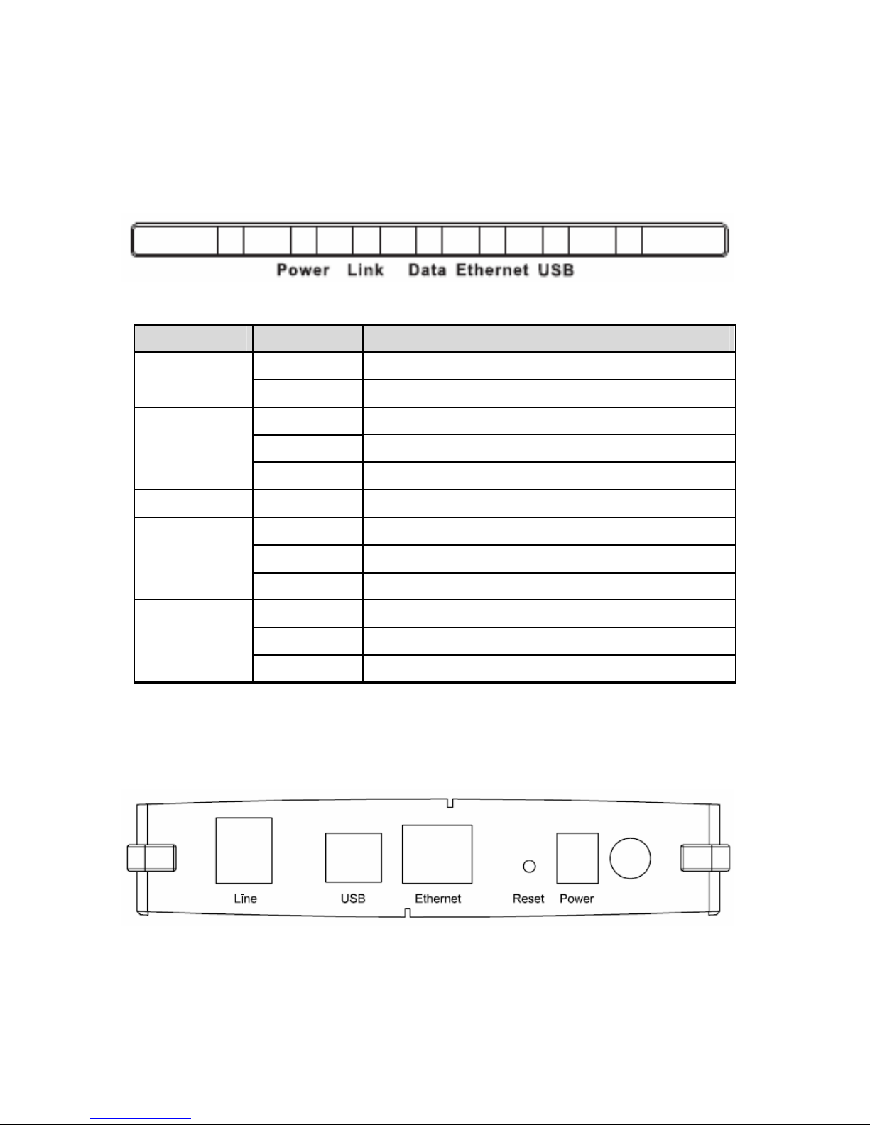
1.5 LED Status
1.5.1 Front Panel
LED Status Description
Off Power is off.
Power
On Power is on and the device operates normally.
Off No signal is detected.
Blink DSL line training is in progress.
Link
On DSL line connection is up.
Data Blink Traffic is in progress.
Off No Ethernet signal is detected.
Blink User data is going through Ethernet port.
Ethernet
On Ethernet interface is ready to work.
Off No signal is detected.
Blink User data is going through USB port.
USB
On USB interface is ready to work.
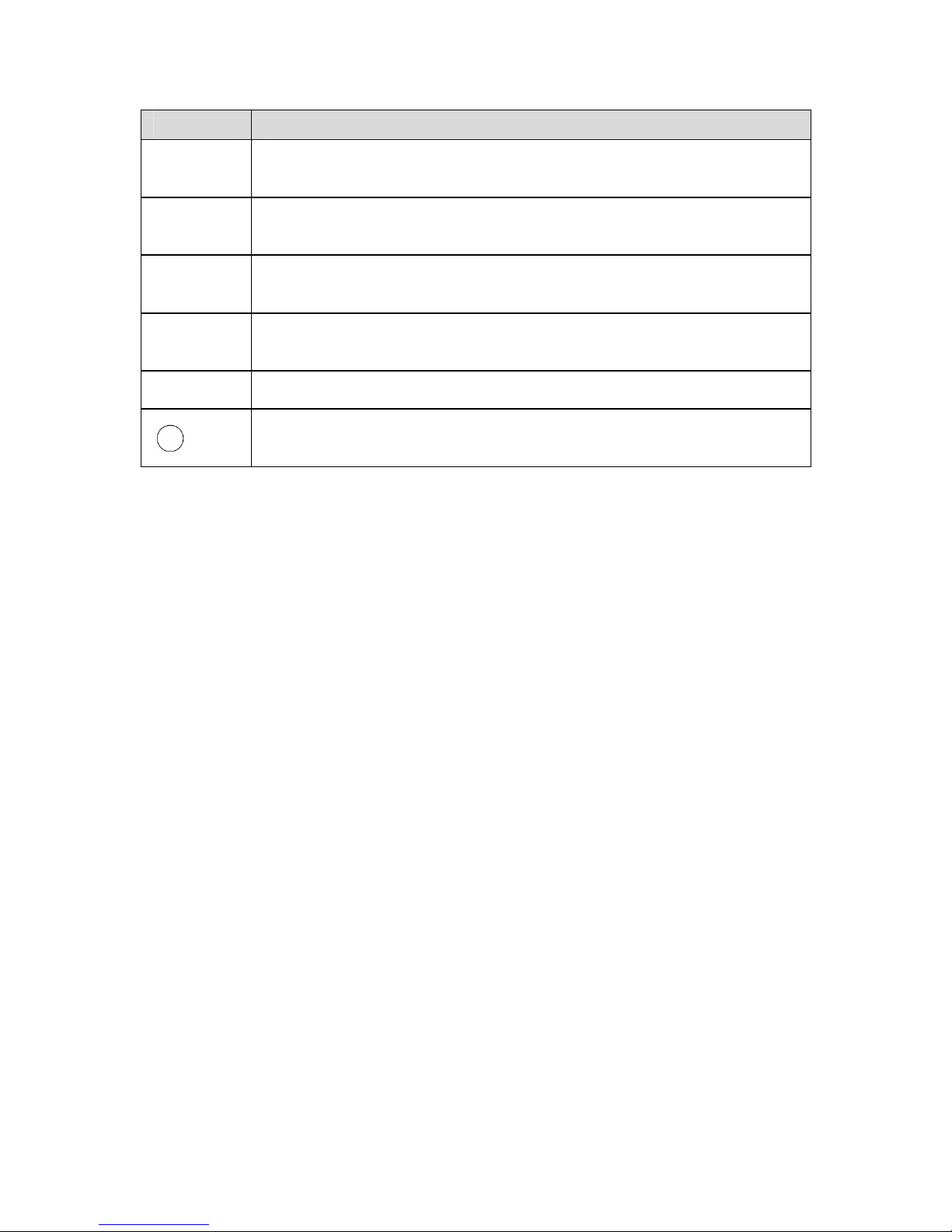
1.5.2 Rear panel
Page 6
4
Interface Description
Line
RJ-11 port: Connect the router to ADSL connector or splitter
through telephone line.
USB
USB device interface for connecting to PC or other network
devices.
Ethernet
RJ-45 port, for connecting the router to a PC or other network
devices through Ethernet cable.
Reset
To restore the factory default, keep the device powered on, push
a needle into the hole for about 1 second, and then release.
Power
Power interface, for connecting the power adapter.
Power switch, on the side of power interface.
The power adapter output: 12 V DC, 500 mA.
2 Hardware Installation
The router contains one Ethernet LAN, and an Line (WAN) interface. Place the
Router in a location where it can be connected to the various devices as well as
to a power source. The router should not be located where it is exposed to
moisture or excessive heat. Make sure the cables and power cord are placed
safely out of the way so they do not create a tripping hazard. As with any
electrical appliance, observe common sense safety procedures.
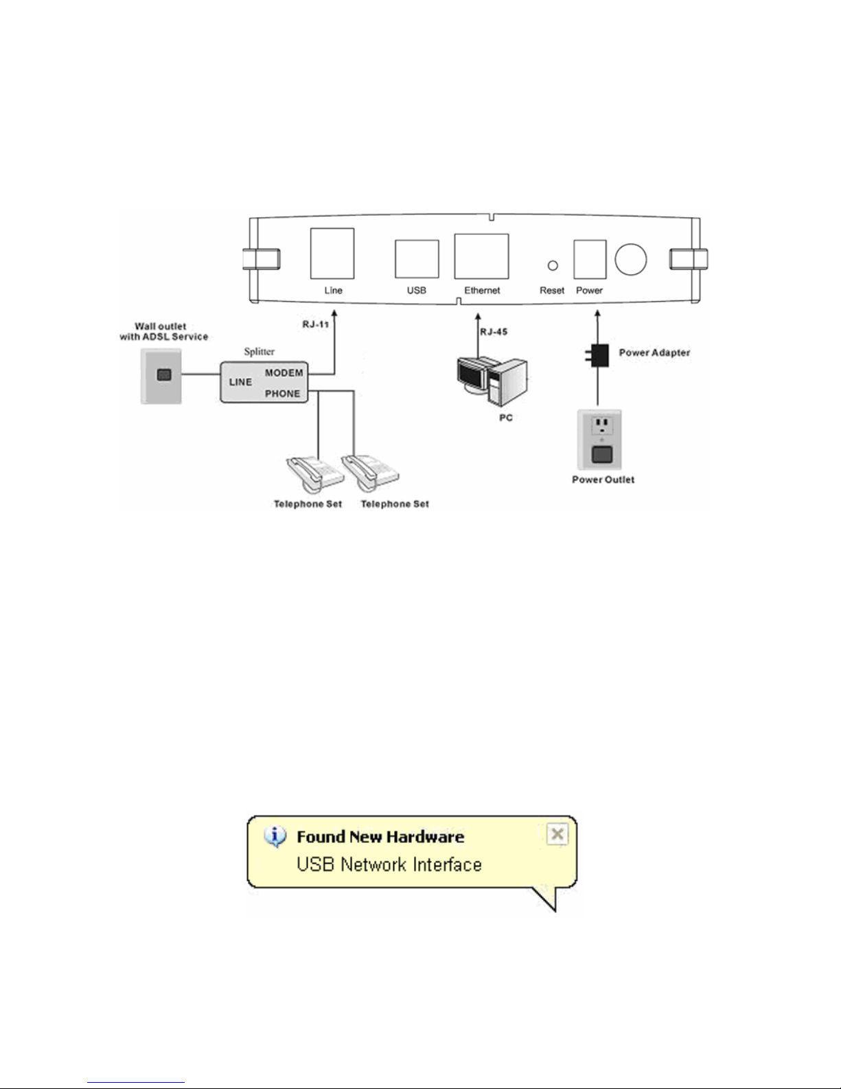
2.1 ADSL Connection of Router
(1) Connect the Line port of the router and the Modem port of the splitter with
a telephone cable; connect the phone to the phone port of the splitter
through a cable; and connect the incoming line to the Line port of the
splitter.
The spliiter has three ports:
LINE: Connect to a wall phone jack (RJ-11 jack)
Modem: Connect to the Line interface of the router
PHONE: Connect to a telephone set
Page 7
5
(2) Connect the Ethernet port of the router to the network card of the PC
through an Ethernet line.
(3) Plug the power adapter to the wall outlet and then connect the other end of
it to the Power port of the router.
2.2 USB Installation
To connect the DSL router to the USB port of PC, perform the following:
Connect the USB cable to the USB port on the DSL router. The cable has
two different connectors; you may have to try both connectors and the
connector is keyed so try different orientations.
Connect the other end of the USB cable into the USB port of PC.
For USB installation on Windows XP, once the PC powers up, a message
appears in the system tray indicating that new hardware is found.
Then, the Found New Hardware Wizard dialog box pops up. Select Install the
software automatically (Recommended) and insert the Manual and Driver
Page 8
6
CD-ROM. Click Next. The system searches CD-ROM for the best USB driver.
Then you can install the USB driver according to the instructions.
3 Web Configuration Management
3.1 Logging In to the Router
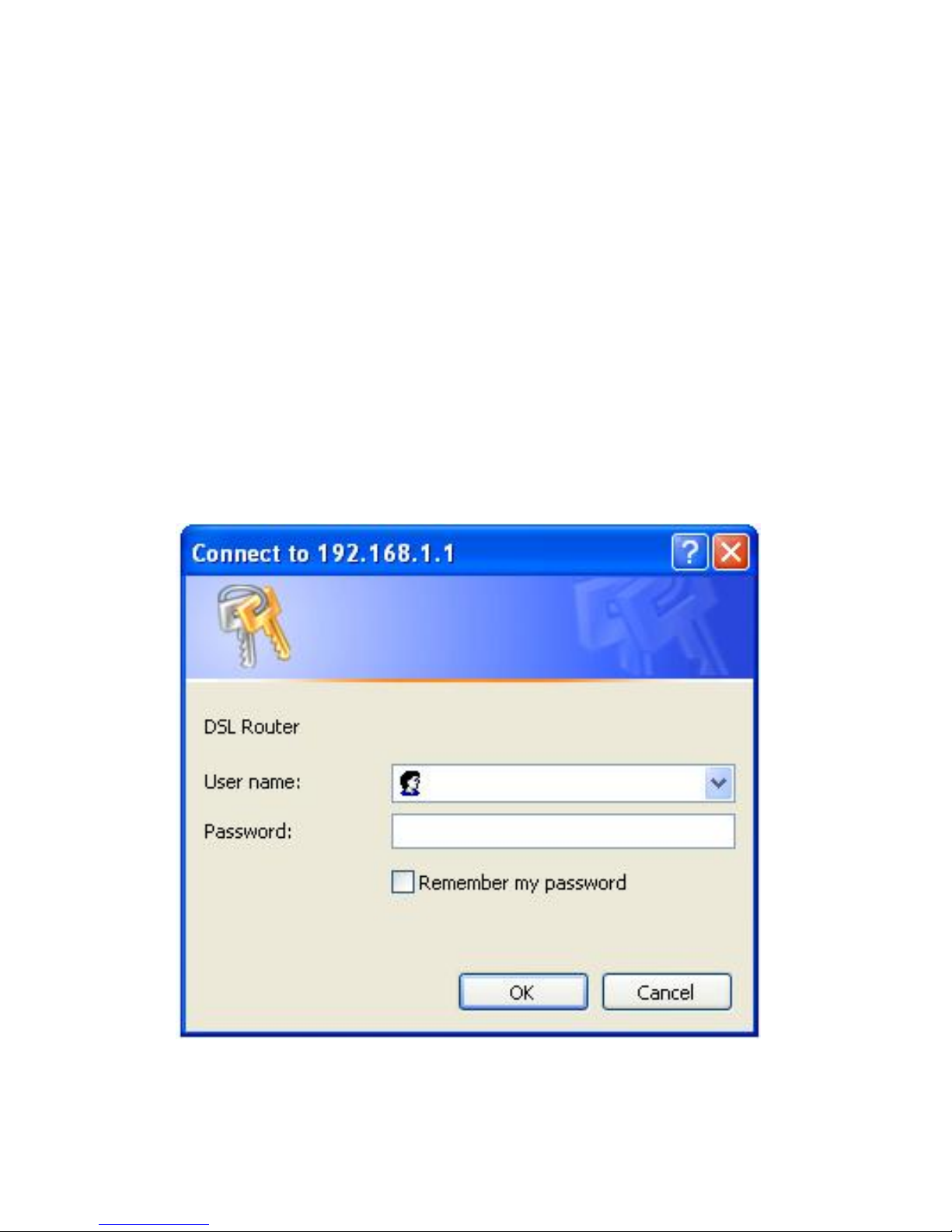
Step 1 Open the Internet Explorer or Netscape Web browser and enter
http://192.168.1.1 (default IP address).
Step 2 Connect the router. Enter the user name and password.
The default user name and password of the super user are admin
and admin.
The default user name and password of the common user are user
and user.
After logging in the router as a super user, you can query, configure, and modify
all configurations of the router. You can also diagnose the router system.
Page 9
7
3.2 Quick Setup – PPPoE
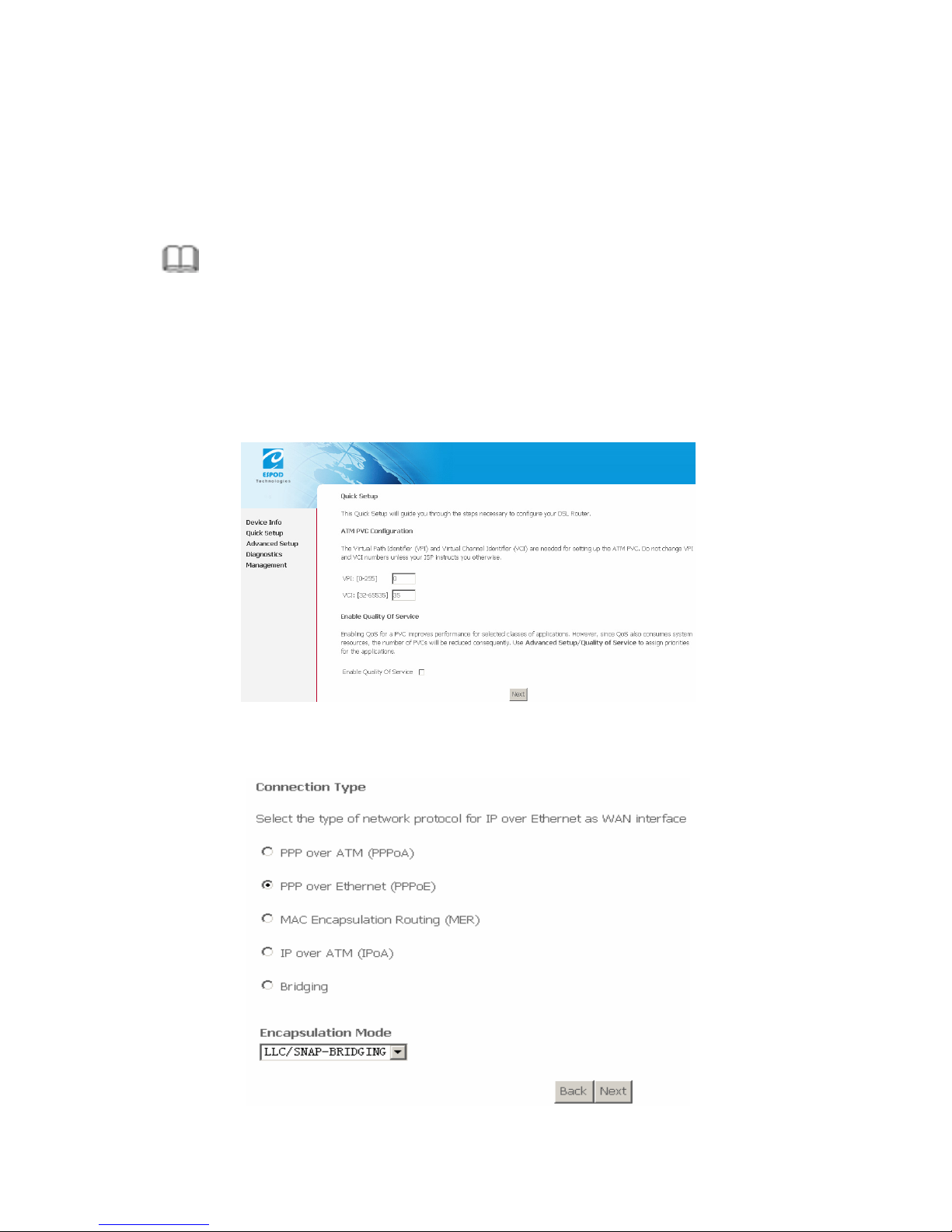
After finishing logging, the Quick Setup page appears shown as the following
figure, if you do not configure the PVC of WAN connection.
Note:
This section describes the procedure for adding PVC 0/35 (PPPoE mode). If
you want to configure the WAN connection in another mode, refer to 3.4.1
WAN Configuration.
Step 1 In this page, you can modify VPI/VCI, and QoS.
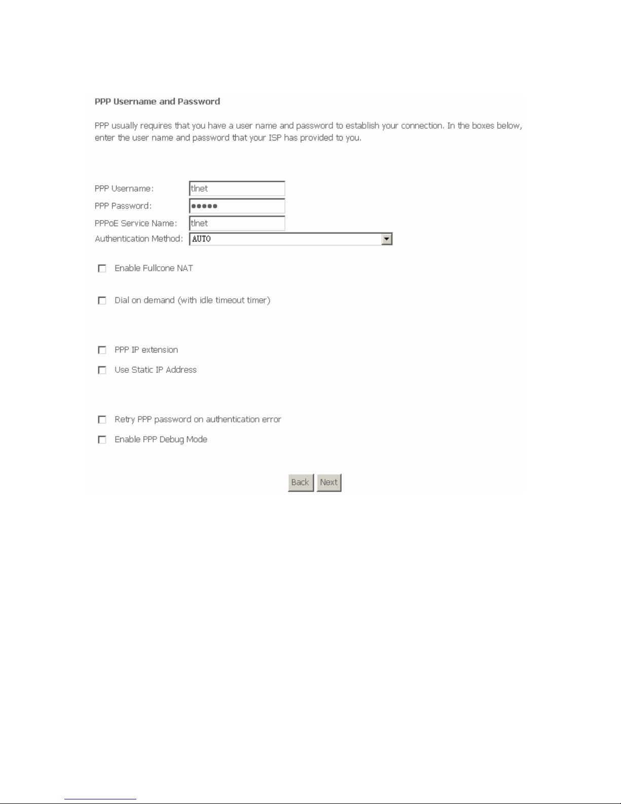
Step 2 Click Next and select the type of network protocol and encapsulation
that your ISP instructs you to use.
Page 10
8
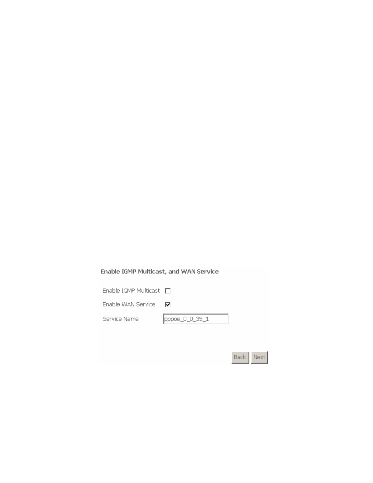
Step 3 After proper configuration, click Next, and the following page appears.
In this page, you can modify the PPP user name, PPP password, authentication
method and so on.
PPP Username: The correct user name that your ISP provides to you.
PPP Password: The correct password that your ISP provides to you.
PPPoE Service Name: If your ISP provides it to you, please enter it. If not,
do not enter any information.
Authentication Method: The value can be AUTO, PAP, CHAP, or
MSCHAP. Usually, you can select AUTO.
Enable Fullcone NAT: A full cone NAT is one where all requests from the
same internal IP address and port are mapped to the same external IP
address and port. Furthermore, any external host can send a packet to the
internal host, by sending a packet to the mapped external address.
Page 11
9
Dial on demand (with idle timeout timer): If this function is enabled, you
need to enter the idle timeout time.
PPP IP extension: If this function is enabled, the WAN IP address
obtained by the router through built-in dial-up can be directly assigned to
the PC being attached to the router (at this time, the router connects to
only one PC).
Use Static IP Address: If this function is disabled, the router obtains an IP
address assigned by an uplink equipment such as BAS, through PPPoE
dial-up. If this function is enabled, the router uses this IP address as the
WAN IP address.
Retry PPP password on authentication error:If this function is enabled,
DSL will retry PPP password on authentication while authenticating with
right password failure.
Enable PPP Debug Mode: The PPP Debug Mode enables connection
debugging facilities. If this function is enabled, pppd will log the contents of
all control packets sent or received in a readable form. The packets are
logged through syslog with facility daemon and level debug.
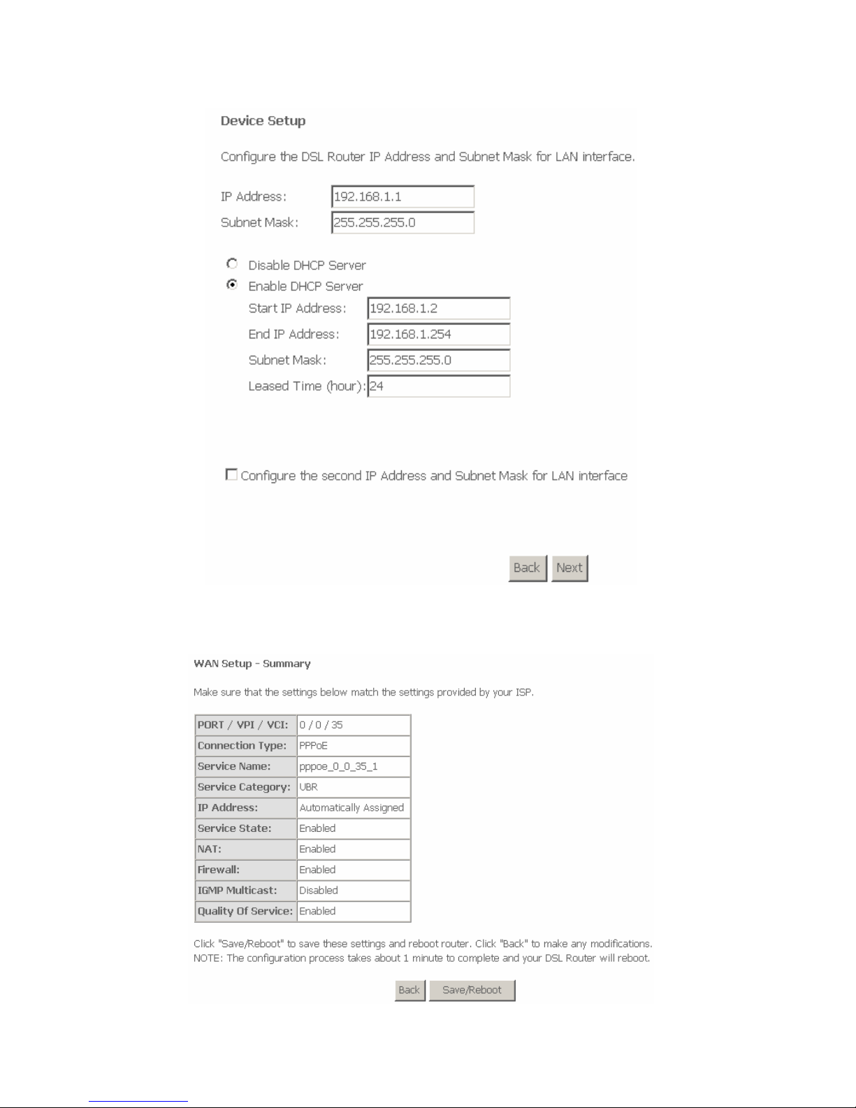
Step 4 After entering the PPP user name and password, click Next and the
following page appears. In this page, you can modify the service name,
and enable or disable the IGMP multicast and WAN service.
IGMP Multicast: IGMP proxy. For example, if you wish that the PPPoE
mode supports IPTV, enable this function.
WAN Service: Enable it, unless you do not want to active the PVC.
Step 5 Click Next and the following page appears. In this page, you can set
the IP Address and Subnet Mask of DSL Router for LAN interface.
Usually, you can use the default configurations.
Page 12
10
Step 6 Click Next and ensure that the below settings match the settings
provided by your ISP. See the following figure.
Page 13
11
Step 7 Click Save/Reboot to save your configurations. The setting for PPPoE
is complete.
Note:
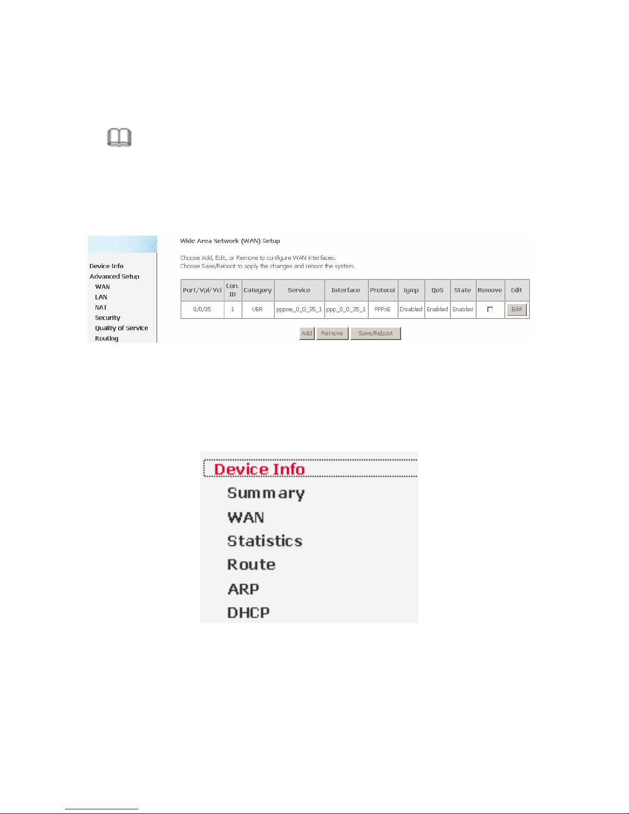
After the Quick Setup is completed, you can add the new WAN configuration
in Advanced Setup. Select Advanced Setup > WAN, the following figure
appears, you can click Add to add WAN configuration.
3.3 DSL Router Device Information
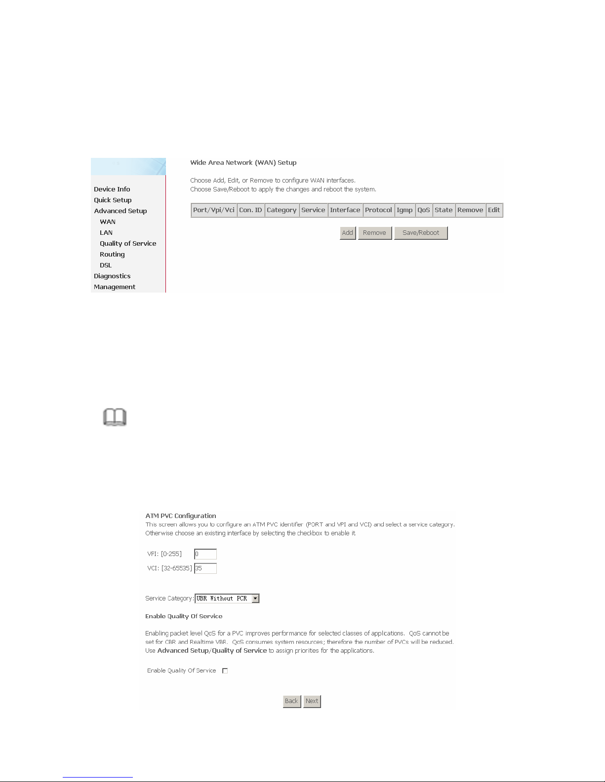
Choose Device Info, the following page appears. Choose items to view the
relative information.
Page 14
12
3.4 Advanced Setup
3.4.1 WAN Configuration
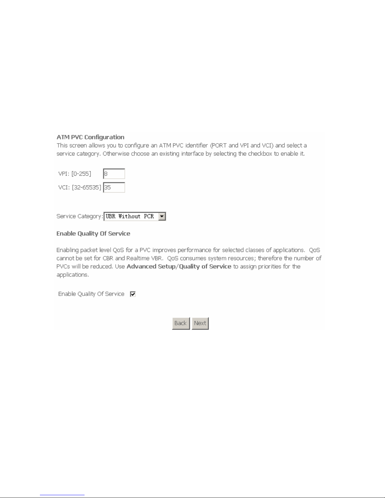
Choose Advance Setup > WAN, the following page appears.
To modify the parameters of an existing PVC, click Edit.
To add an ATM PVC, click Add.
To delete a PVC, select the Remove check box in the table and click
Remove.
Click Save/Reboot to apply the changes and reboot the router.
Note:
After a PVC is deleted or modified, the system must be rebooted. Otherwise,
the modification does not take effect.
Click Add. The configure page displayed contains the following information:
Page 15
13
This page the same as the Quick Setup page. The procedure for adding a PVC
is described as follows.
3.4.1.1 Adding a PPPoE PVC
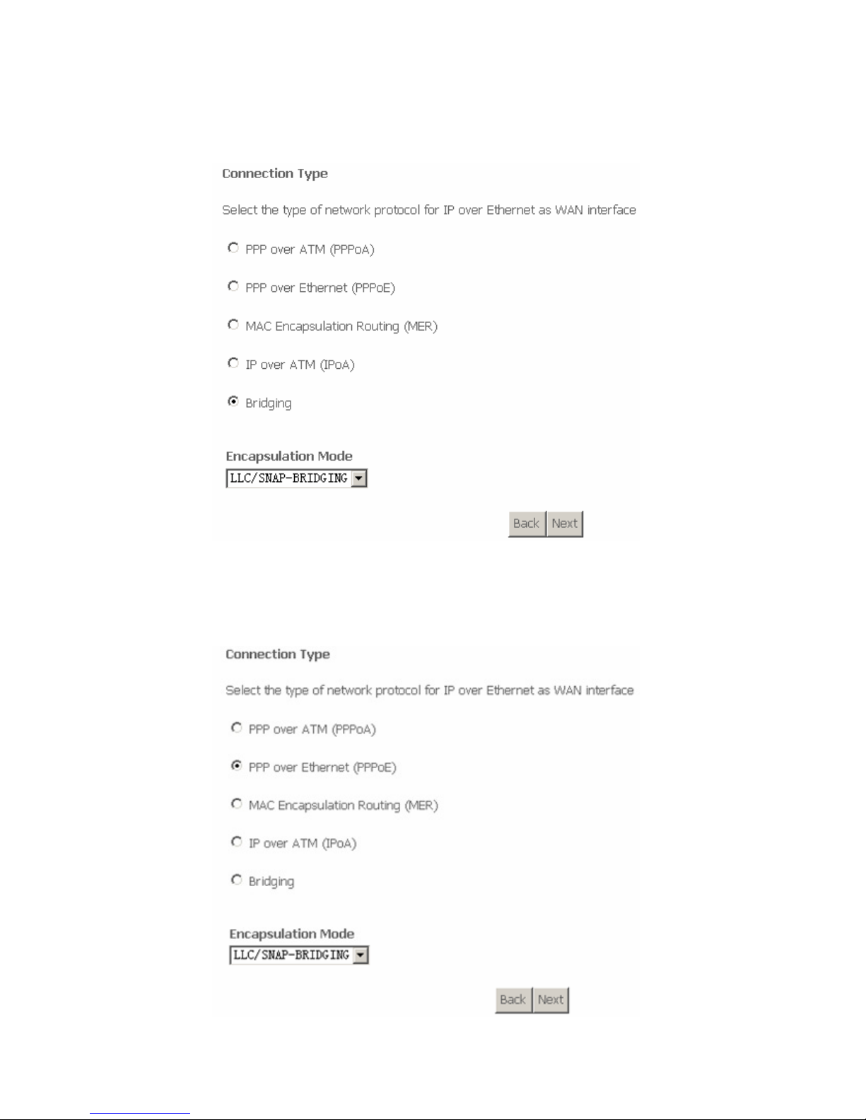
This section describes the procedure for adding PVC 8/35 (PPPoE mode).
Click Add and the following page appears. In this page, you can modify VPI/VCI,
service categories, and QoS.
VPI: Virtual path between two points in an ATM network. Its valid value
range is from 0 to 255.
VCI: Virtual channel between two points in an ATM network. Its valid value
range is from 32 to 65535 (1 to 31 are reserved for known protocols).
Service Category: UBR Without PCR/UBR With PCR/CBR/Non Realtime
VBR/Realtime VBR.
Enable Quality Of Service: Enable or disable QoS.
In this example, PVC 8/35 is to be modified and the default values of service
category and QoS remain. In actual applications, you can modify them as
required.
Page 16
14
After proper modifications, click Next and the following page appears.
In this page, you can modify the Internet connection type and encapsulation type.
Change the connection type of PVC 8/35 to PPP over Ethernet (PPPoE) and set
the Encapsulation Mode to LLC/SNAP-BRIDGING (according to the uplink
equipment).
Page 17
15
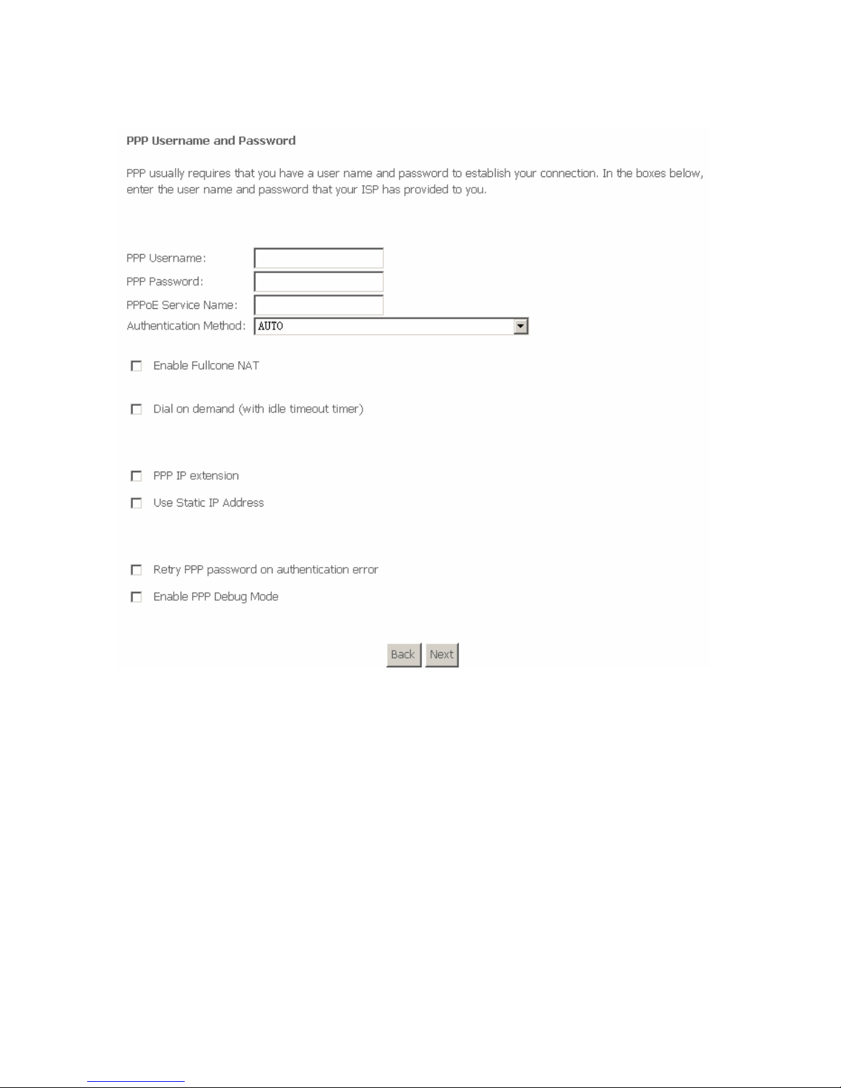
Click Next and the following page appears.
In this page, you can modify the PPP user name, PPP password, authentication
method and so on.
PPP Username: The correct user name that your ISP provides to you.
PPP Password: The correct password that your ISP provides to you.
PPPoE Service Name: If your ISP provides it to you, please enter it. If not,
do not enter any information.
Authentication Method: The value can be AUTO, PAP, CHAP, or
MSCHAP. Usually, you can select AUTO.
Enable Fullcone NAT: A full cone NAT is one where all requests from the
same internal IP address and port are mapped to the same external IP
address and port. Furthermore, any external host can send a packet to the
internal host, by sending a packet to the mapped external address.
Page 18

16
Dial on demand (with idle timeout timer): If this function is enabled, you
need to enter the idle timeout time. Within the preset minutes, if the router
does not detect the flow of the user continuously, the router automatically
stops the PPPoE connection. Once it detects the flow (like access to a
webpage), the router restarts the PPPoE dialup.
If this function is disabled, the router performs PPPoE dial-up all the time. The
PPPoE connnection does not stop, unless the router is powered off and DSLAM
or uplink equipment is abnormal.
PPP IP extension: If this function is enabled, the WAN IP address
obtained by the router through built-in dial-up can be directly assigned to
the PC being attached to the router (at this time, the router connects to
only one PC). From the aspect of the PC user, the PC dials up to obtain an
IP addres. But actually, the dial-up is done by the router.
If this function is disabled, the router itself obtains the WAN IP address.
Use Static IP Address: If this function is disabled, the router obtains an IP
address assigned by an uplink equipment such as BAS, through PPPoE
dial-up.
If this function is enabled, the router uses this IP address as the WAN IP address.
Retry PPP password on authentication error:If this function is enabled,
DSL will retry PPP password on authentication while authenticating with
right password failure.
Enable PPP Debug Mode: The PPP Debug Mode enables connection
debugging facilities. If this function is enabled, pppd will log the contents of
all control packets sent or received in a readable form. The packets are
logged through syslog with facility daemon and level debug.
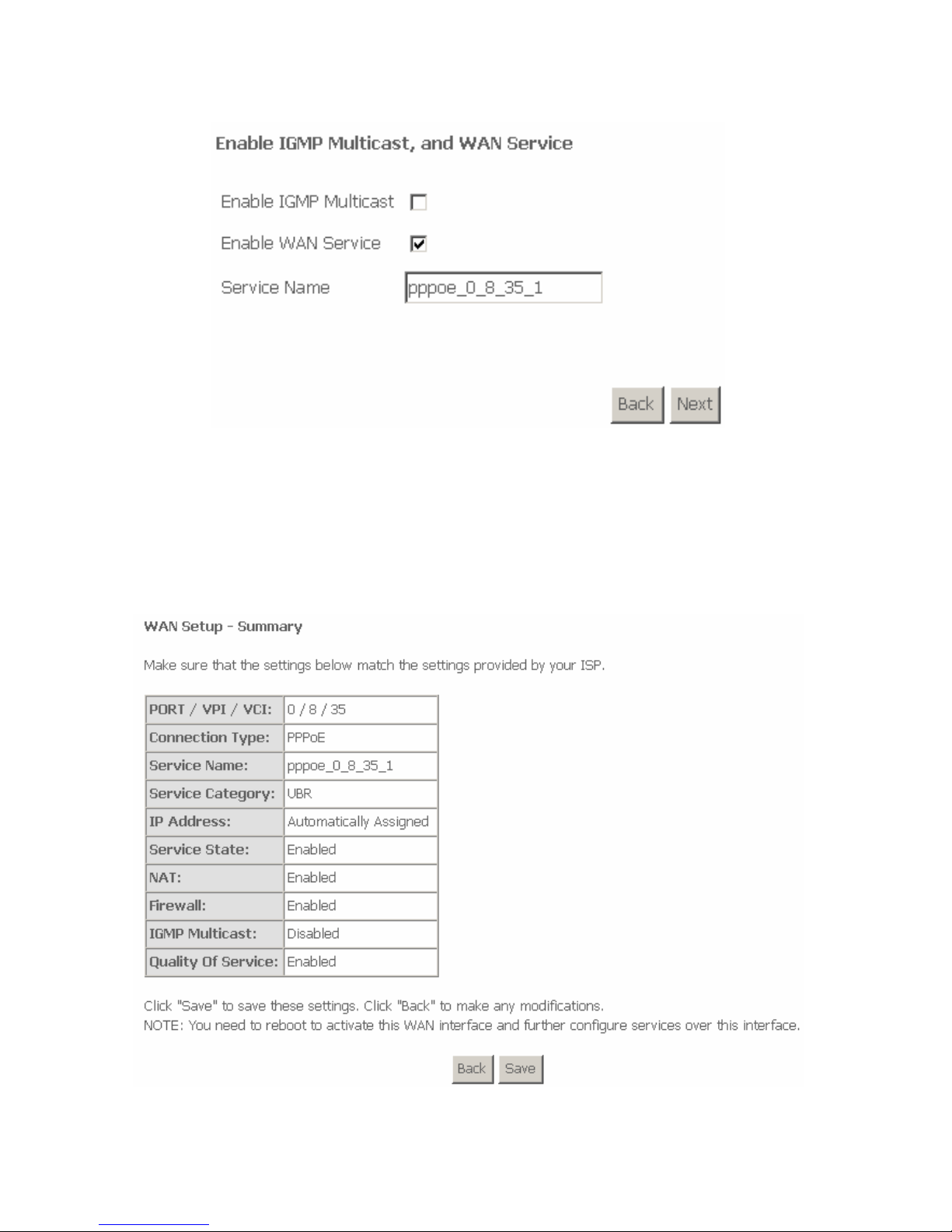
After entering the PPP user name and password, click Next and the following
page appears.
In this page, you can modify the service name, and enable or disable the IGMP
multicast and WAN service.
Page 19
17
IGMP Multicast: IGMP proxy. For example, if you wish that the PPPoE
mode supports IPTV, enable this function.
WAN Service: Enable it, unless you do not want to active the PVC.
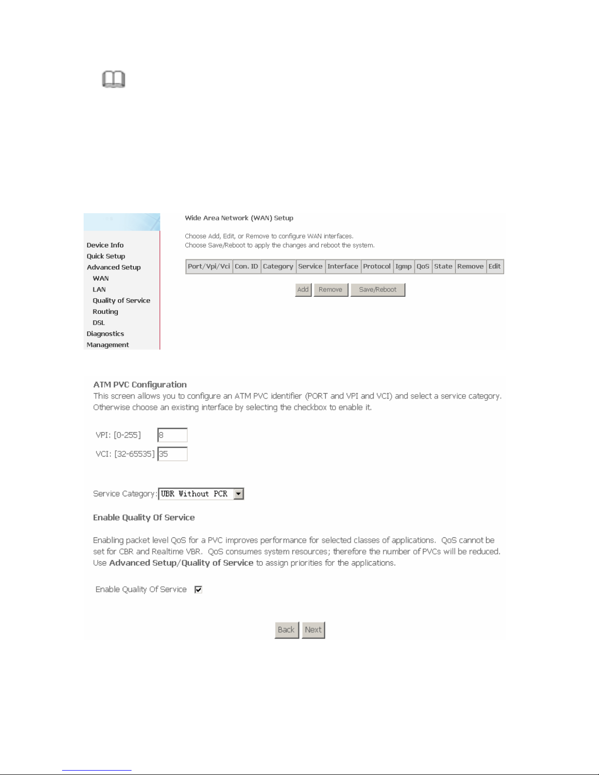
Click Next and the following page appears.
This page shows all the configuration. You can view the default values of network
address translation (NAT) enable and Firewall enable.
To save the settings, click Save. To make any modifications, click Back.
Page 20
18
Note:
You need to reboot the router to activate this WAN interface and further
configure services in this interface.
3.4.1.2 Adding a PPPoA PVC
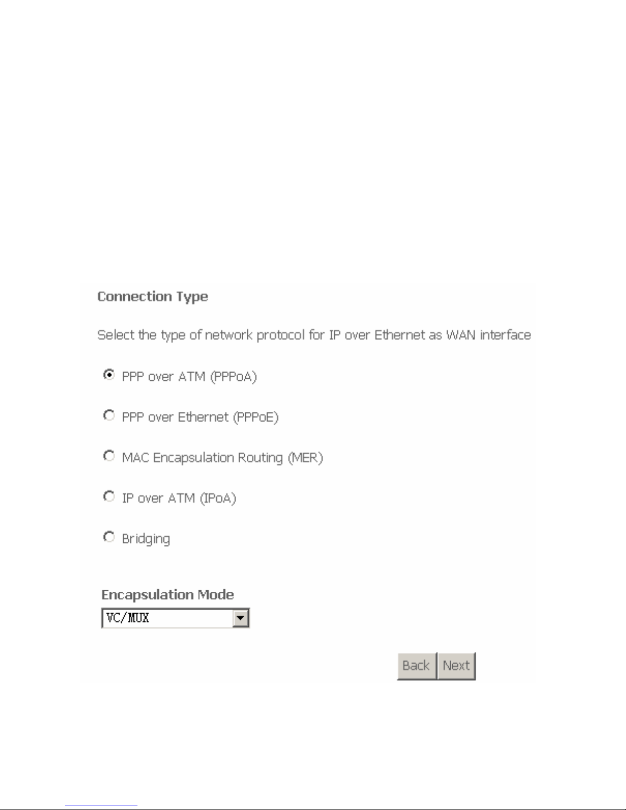
This section describes the procedure for adding PVC 8/35 (PPPoA mode).
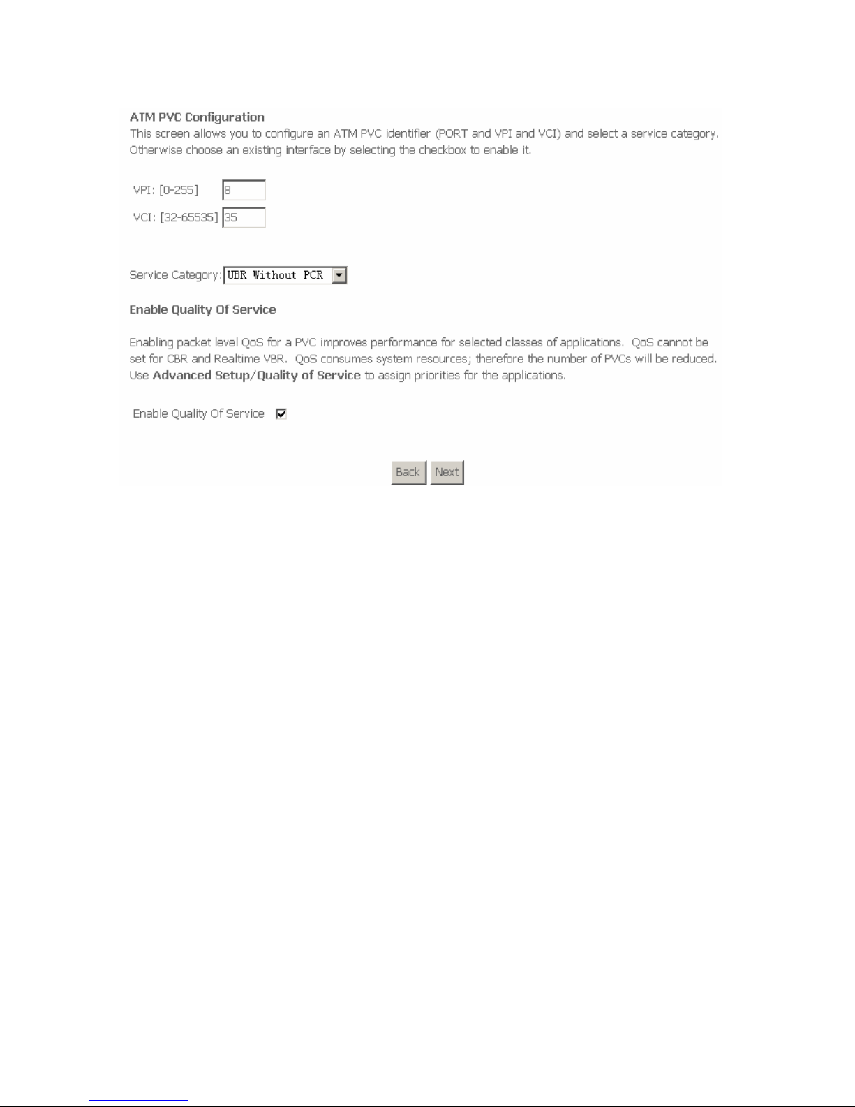
Click Add and the following page appears.
In this page, you can modify VPI/VCI, service categories, and QoS.
VPI: Virtual path between two points in an ATM network. Its valid value range is
from 0 to 255.
Page 21
19
VCI: Virtual channel between two points in an ATM network. Its valid value range
is from 32 to 65535 (1 to 31 are reserved for known protocols).
Service Category: UBR Without PCR/UBR With PCR/CBR/Non Realtime
VBR/Realtime VBR.
Enable Quality Of Service: Enable or disable QoS.
In this example, PVC 8/35 is to be modified and the default values of service
category and QoS remain. In actual applications, you can modify them as
required.
After proper modifications, click Next and the following page appears.
In this page, you can modify the Internet Connection Type and Encapsulation
Type.
Click Next and the following page appears.
Page 22
20
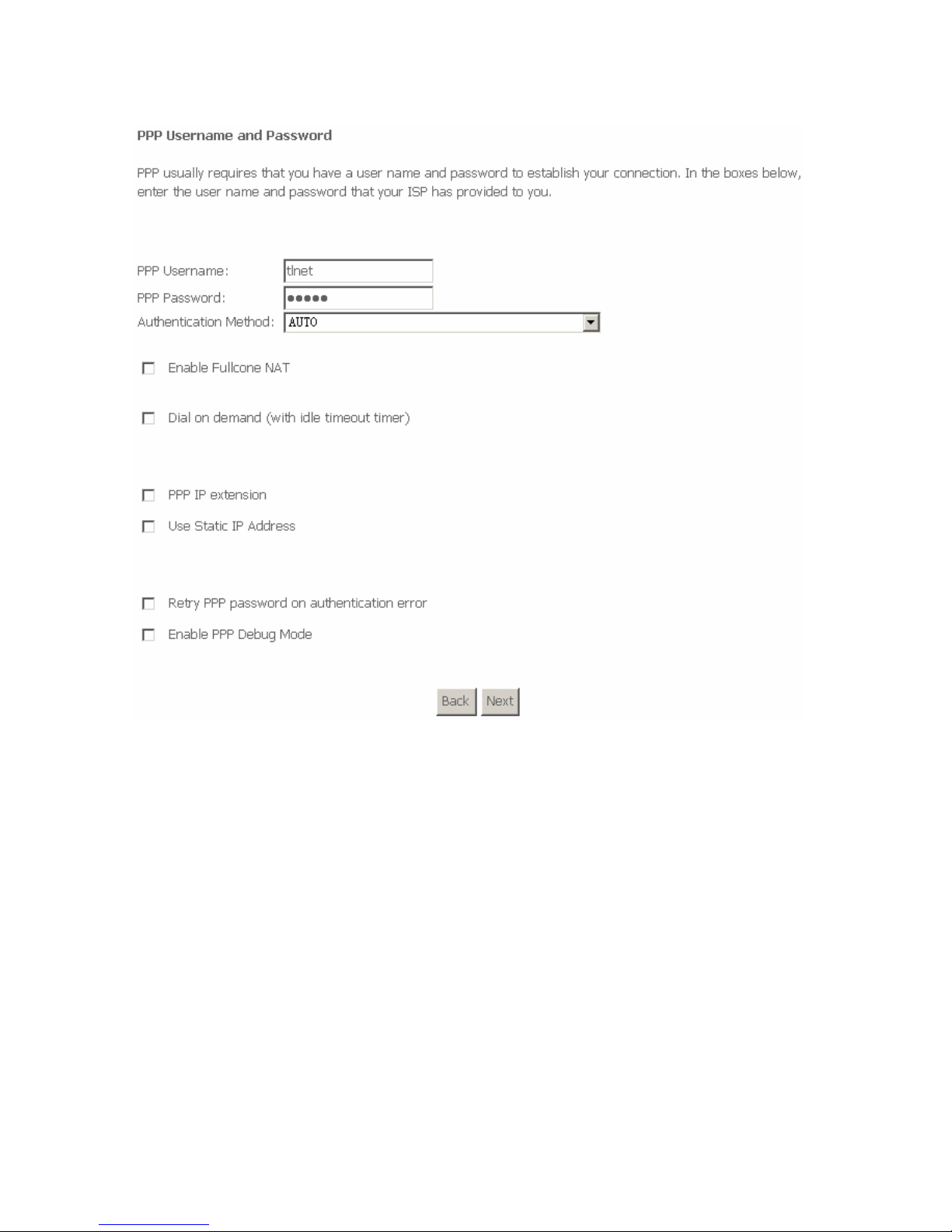
In this page, you can modify the PPP user name, PPP password, authentication
method and so on.
PPP Username: The correct user name that your ISP provides to you.
PPP Password: The correct password that your ISP provides to you.
Authentication Method: The value can be AUTO, PAP, CHAP, or
MSCHAP. Usually, you can select AUTO.
Enable Fullcone NAT: A full cone NAT is one where all requests from the
same internal IP address and port are mapped to the same external IP
address and port. Furthermore, any external host can send a packet to the
internal host, by sending a packet to the mapped external address.
Dial on demand (with idle timeout timer): If this function is enabled, you
need to enter the idle timeout time.
Page 23
21
PPP IP extension: If this function is enabled, the WAN IP address
obtained by the router through built-in dial-up can be directly assigned to
the PC being attached to the router (at this time, the router connects to
only one PC).
Use Static IP Address: If this function is disabled, the router obtains an IP
address assigned by an uplink equipment such as BAS, through PPPoA
dial-up. If this function is enabled, the router uses this IP address as the
WAN IP address.
Retry PPP password on authentication error:If this function is enabled,
DSL will retry PPP password on authentication while authenticating with
right password failure.
Enable PPP Debug Mode: The PPP Debug Mode enables connection
debugging facilities. If this function is enabled, pppd will log the contents of
all control packets sent or received in a readable form. The packets are
logged through syslog with facility daemon and level debug.
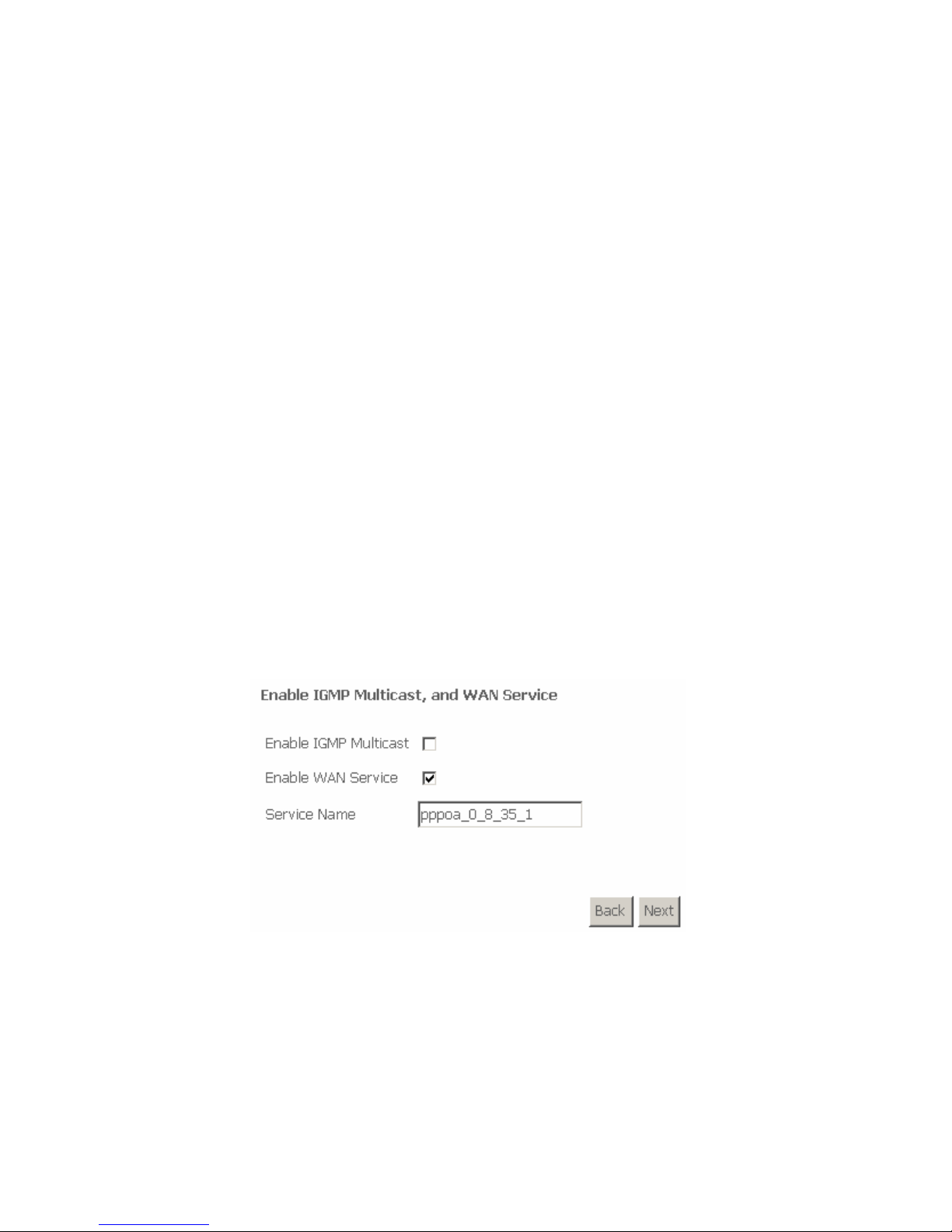
After entering the PPP user name and password, click Next and the following
page appears.
In this page, you can modify the service name, and enable or disable the IGMP
multicast and WAN service.
IGMP Multicast: IGMP proxy. For example, if you wish that the PPPoA mode
supports IPTV, enable this function.
WAN Service: Enable it, unless you do not want to active the PVC.
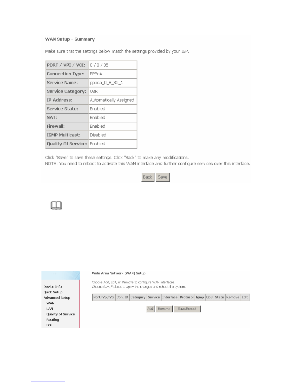
Click Next and the following page appears.
This page shows all the configuration. You can view the default values of NAT
enable and Firewall enable.
Page 24
22
To save the settings, click Save. To make any modifications, click Back.
Note:
You need to reboot the router to activate this WAN interface and further
configure services in this interface.
3.4.1.3 Adding an MER PVC
This section describes the procedure for adding PVC 8/35 (MER mode).
Click Add and the following page appears.
In this page, you can modify VPI/VCIs, service categories and QoS.
Page 25
23
VPI: The virtual path between two points in an ATM network, and its valid value is
from 0 to 255.
VCI: Virtual channel between two points in an ATM network. Its valid value range
is from 32 to 65535 (1 to 31 are reserved for known protocols).
Service Category: UBR Without PCR/UBR With PCR/CBR/Non Realtime
VBR/Realtime VBR.
Enable Quality Of Service: Enable or disable QoS.
In this example, PVC 8/35 is to be modified and the default values of service
category and QoS remain. In actual applications, you can modify them as
required.
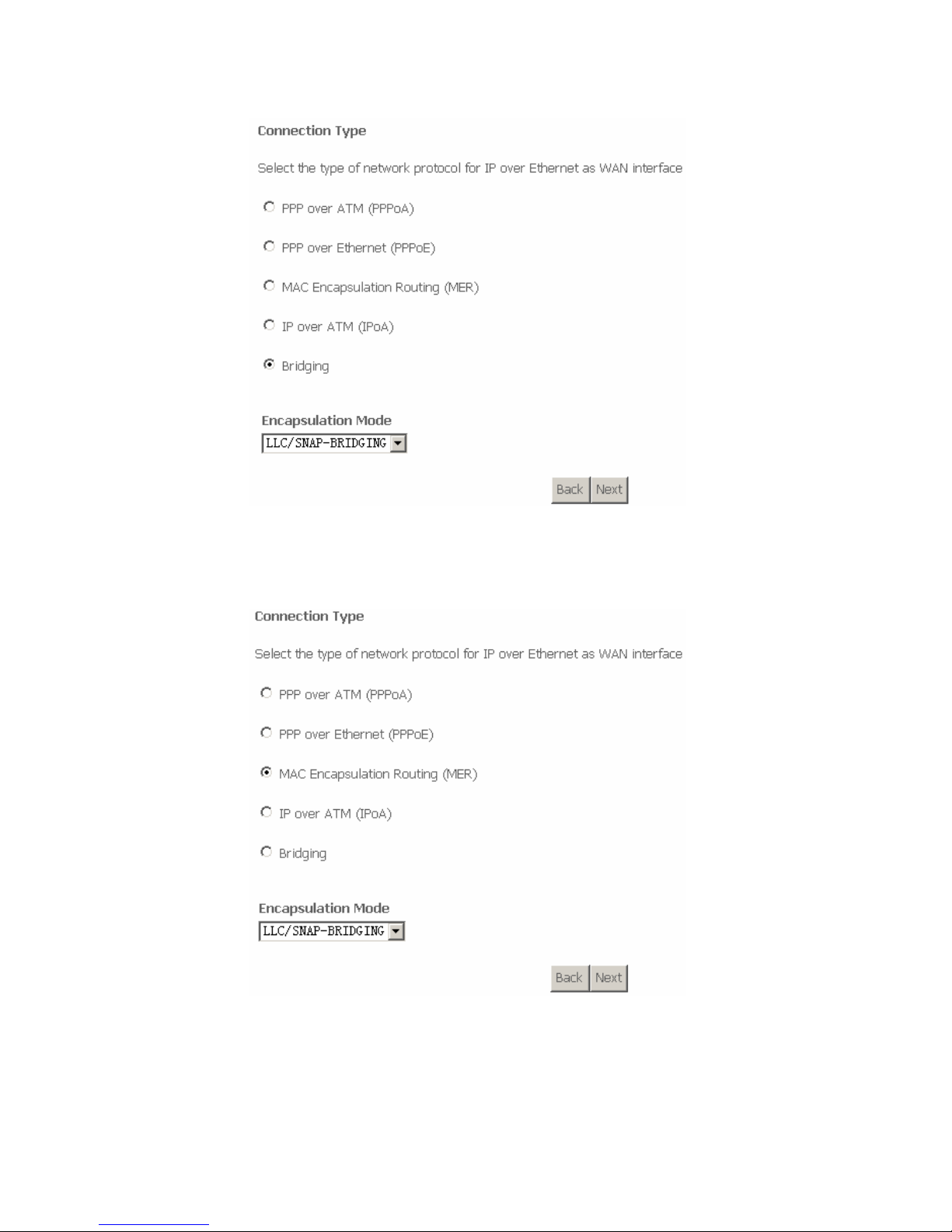
After proper modifications, click Next and the following page appears.
In this page, you can modify the Internet Connection Type and Encapsulation
Mode.
Page 26
24
Change the connection type of PVC 8/35 to MAC Encapsulation Routing (MER)
and set the Encapsulation Mode to LLC/SNAP-BRIDGING (according to the
uplink equipment).
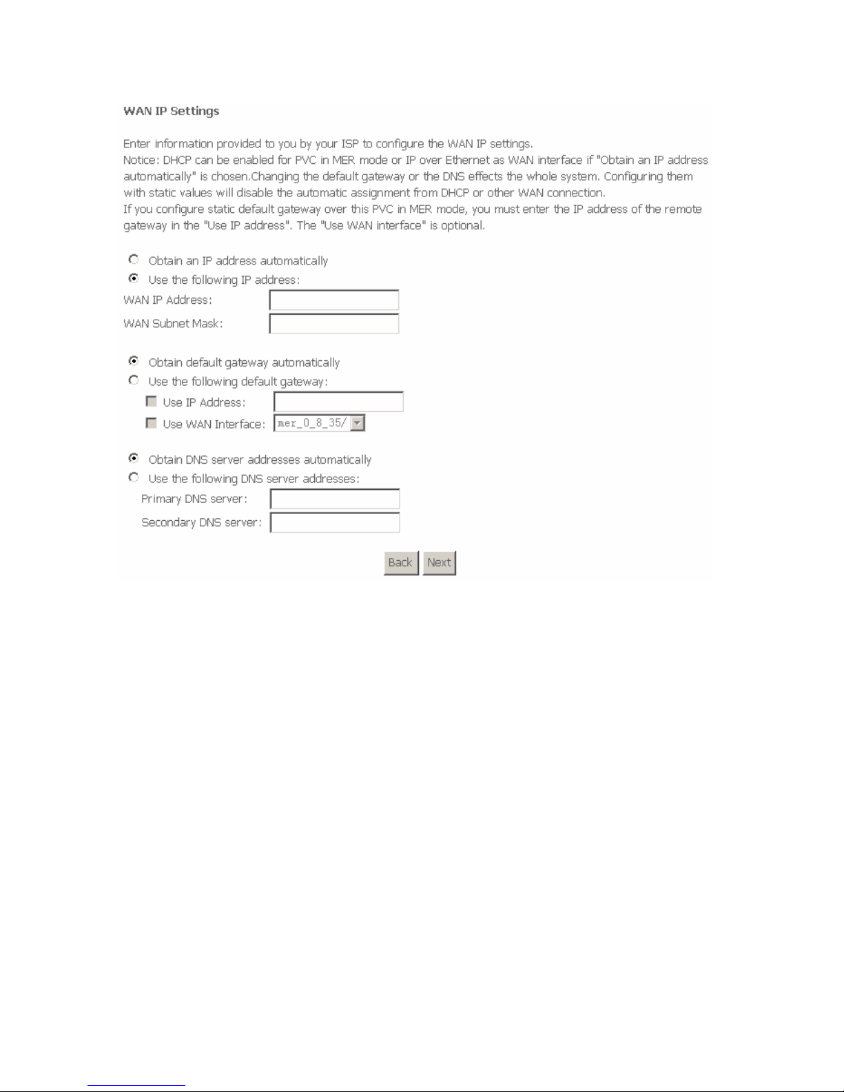
Click Next and the following page appears.
In this page, you can modify the WAN IP address, default gateway, and DNS
server settings.
Page 27
25
Obtain an IP address automatically: The router obtains a WAN IP address
automatically and at this time it enables DHCP client functions. The WAN IP
address is obtained from the uplink equipment like BAS and the uplink equipment
is required to enable the DHCP server functions.
Use the following IP address: If you want to manually enter the WAN IP
address, select this check box and enter the information in the field.
WAN IP Address: Enter the IP address of the WAN interface provided by your
ISP.
WAN Subnet Mask: Enter the subnet mask concerned to the IP address of the
WAN interface provided by your ISP.
Obtain Default Gateway automatically: Obtain the IP address of the default
gateway assigned by the uplink equipment such as BAS.
Use the following Default Gateway: If you want to manually enter the IP
address of the default gateway, select this check box and enter the information in
the fields.
Use IP Address: Enter the gateway of the WAN interface provided by your ISP.
Page 28
26
Use WAN Interface: As to BAS equipment, it is the IP address of the downlink
interface.
Obtain DNS server address automatically: To obtain the IP address of the
DNS server assigned by the uplink equipment such as BAS.
Use the following DNS server addresses: If you want to manually enter the IP
address of the DNS server, select this check box and enter the information in the
fields.
Primary DNS server: Enter the IP address of the primary DNS server.
Secondary DNS server: Enter the IP address of the secondary DNS server
provided by your ISP.
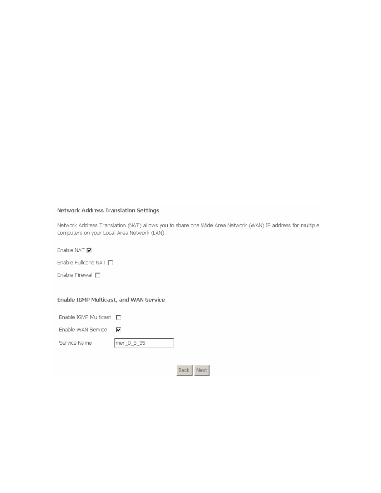
After proper modifications, click Next and the following page appears.
In this page, you can modify the service name, and enable or disable the NAT,
firewall, IGMP multicast, and WAN service.
Enable NAT: Select it to enable the NAT functions of the router. If you do not
want to enable NAT and wish the router user to access the Internet normally, you
must add a route on the uplink equipment. Otherwise, the access to the Internet
fails. Normally, NAT should be enabled.
Enable Fullcone NAT: A full cone NAT is one where all requests from the same
internal IP address and port are mapped to the same external IP address and
Page 29
27
port. Furthermore, any external host can send a packet to the internal host, by
sending a packet to the mapped external address.
Enable Firewall: Enable or disable IP filtering.
IGMP Multicast: IGMP proxy. For example, if you wish that the MER mode
supports IPTV, enable this function.
WAN Service: Enable it, unless you do not want to active the PVC.
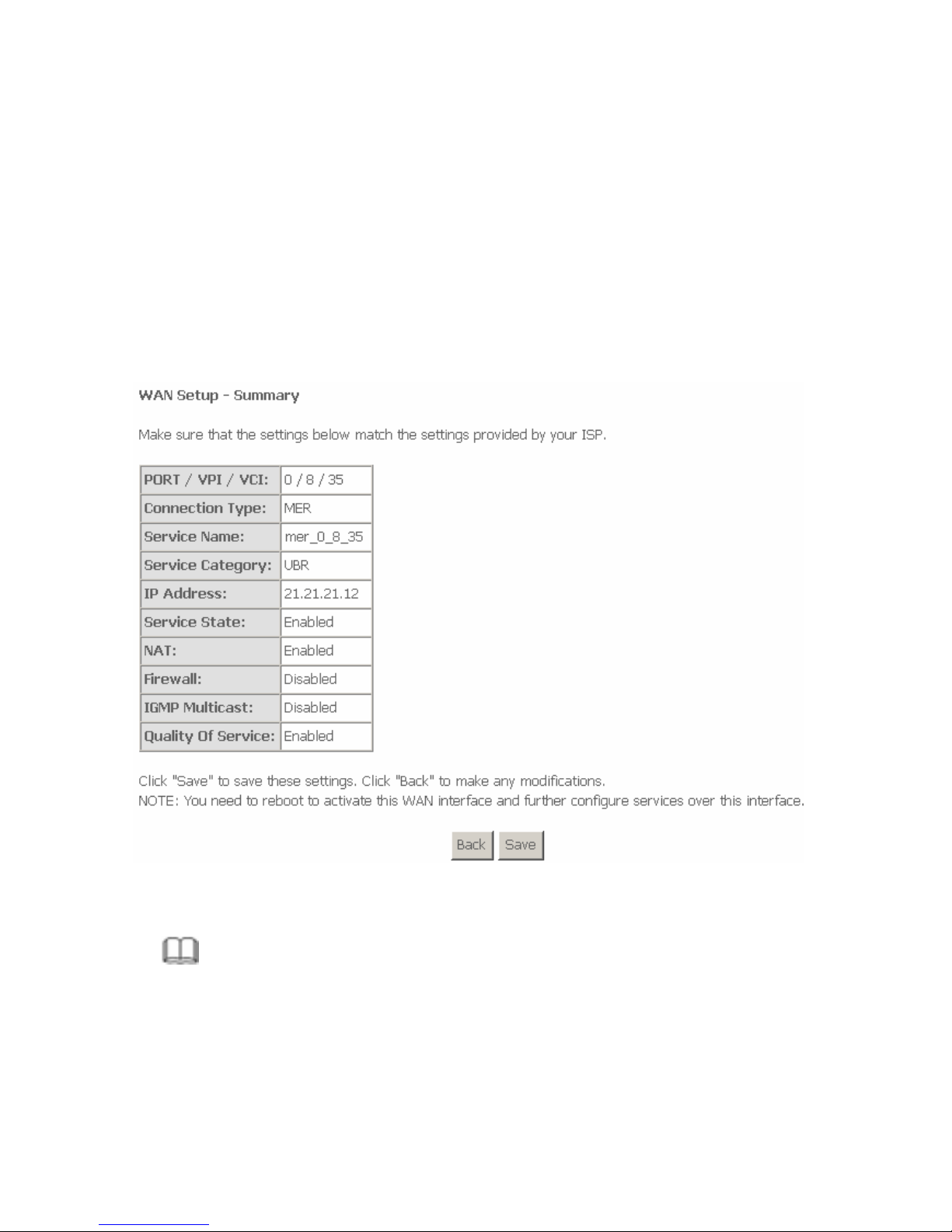
Click Next and the following page appears. This page shows all the
configuration.
To save the settings, click Save. To make any modifications, click Back.
Note:
You need to reboot the router to activate this WAN interface and further
configure services in this interface.
Page 30
28
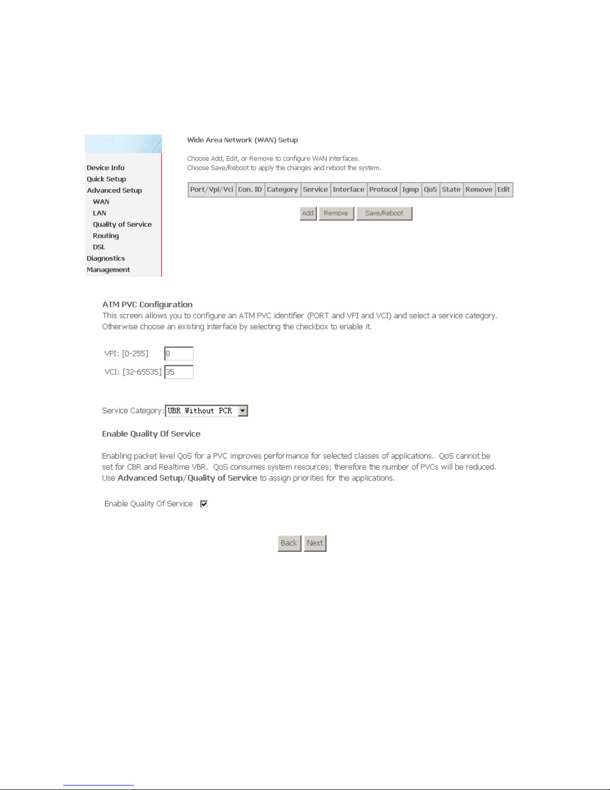
3.4.1.4 Adding an IPoA PVC
This section describes the procedure for adding PVC 8/35 (IPoA mode).
Click Add and the following page appears.
In this page, you can modify VPI/VCIs, service categories, and QoS.
VPI: Virtual path between two points in an ATM network. Its valid value range is
from 0 to 255.
VCI: Virtual channel between two points in an ATM network. Its valid value range
is from 32 to 65535 (1 to 31 are reserved for known protocols).
Service Category: UBR Without PCR/UBR With PCR/CBR/Non Realtime
VBR/Realtime VBR.
Enable Quality Of Service: Enable or disable QoS.
Page 31
29
In this example, PVC 8/35 is to be modified and the default values of service
category and QoS remain. In actual applications, you can modify them as
required.
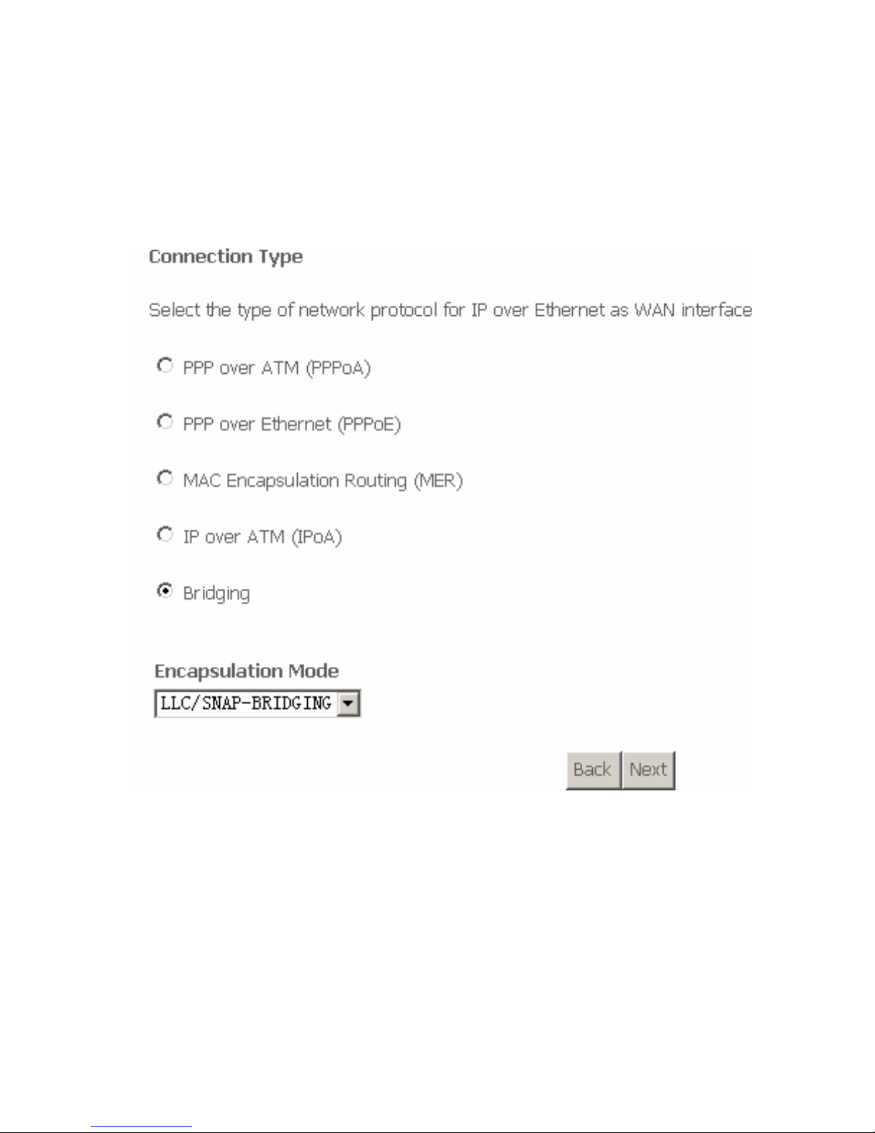
After proper modifications, click Next and the following page appears.
In this page, you can modify the Internet connection type and encapsulation type.
Change the connection type of PVC 8/35 to IP over ATM (IPoA) and set the
Encapsulation Mode to LLC/SNAP-ROUTING (according to the uplink
equipment).
Page 32
30
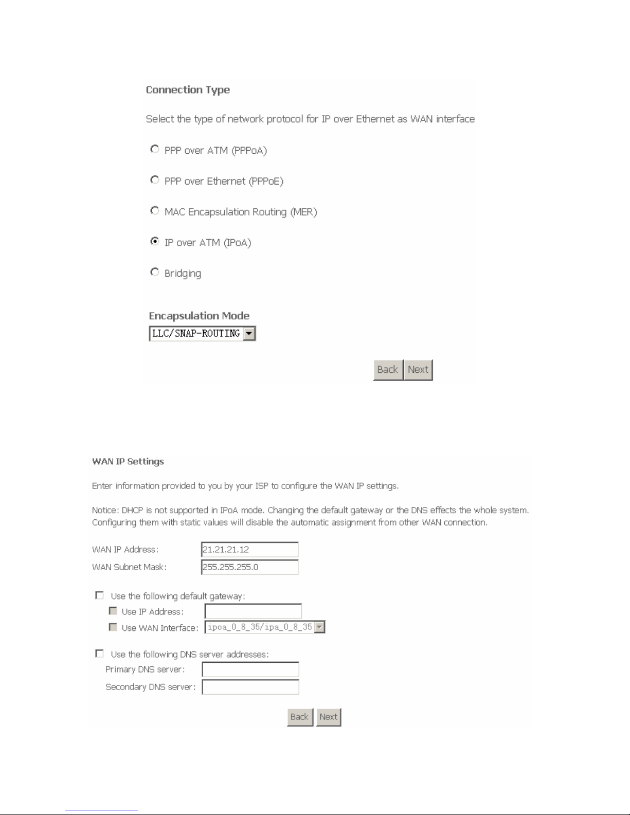
Click Next and the following page appears.
In this page, you can modify the WAN IP, default gateway, and DNS server
settings.
Page 33
31
WAN IP Address: Enter the IP address of the WAN interface provided by your
ISP.
WAN Subnet Mask: Enter the subnet mask concerned to the IP address of the
WAN interface provided by your ISP.
Use the following Default Gateway: If you want to manually enter the IP
address of the default gateway, select this check box and enter the information in
the fields.
Use IP Address: Enter the gateway of the WAN interface provided by your ISP.
Use WAN Interface: As to BAS equipment, it is the IP address of the downlink
interface.
Use the following DNS server addesses: If you want to manually enter the IP
address of the DNS server, select this check box and enter the information in the
fields.
Primary DNS server: Enter the IP address of the primary DNS server.
Secondary DNS server: Enter the IP address of the secondary DNS server
provided by your ISP.
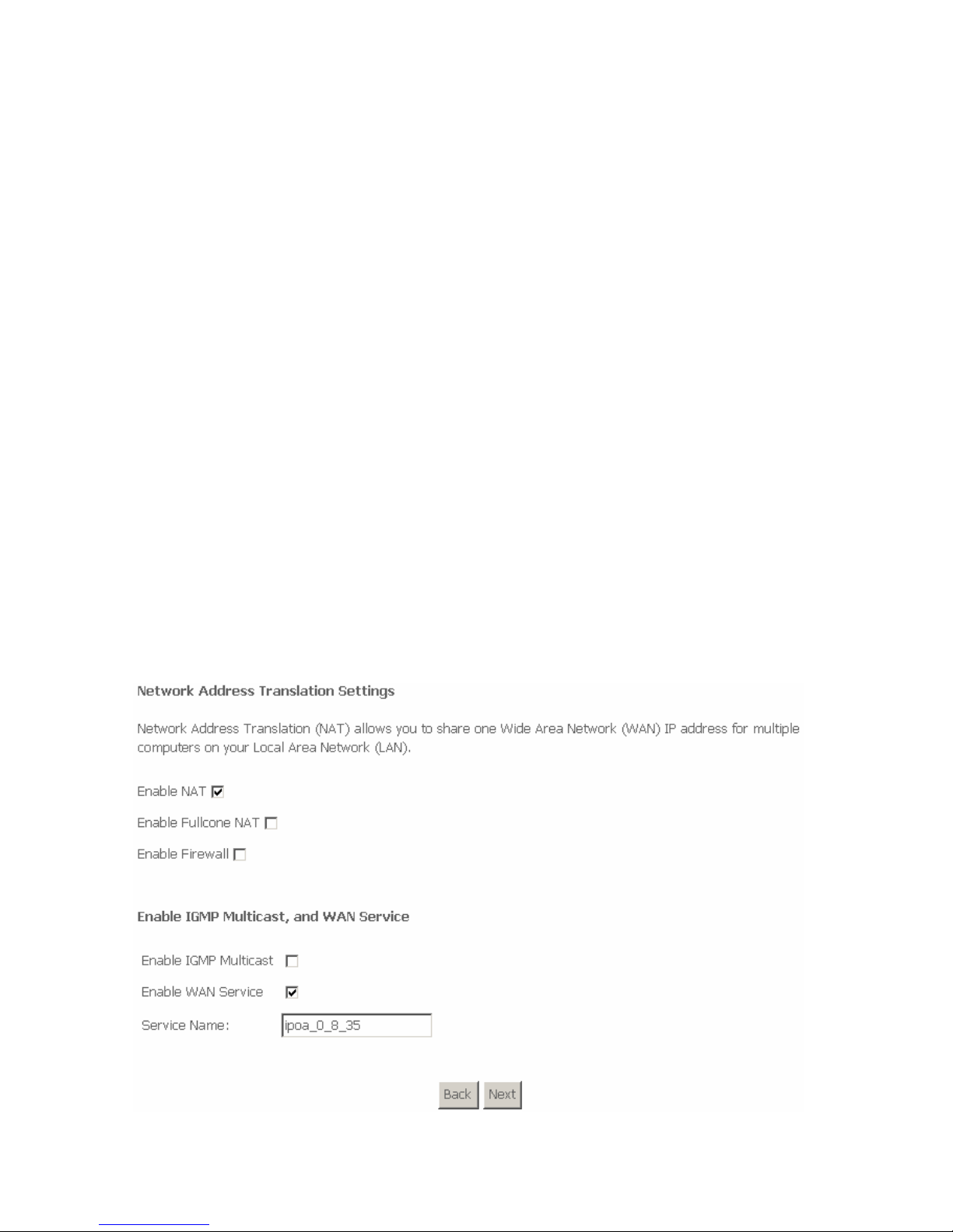
After proper modifications, click Next and the following page appears.
In this page, you can modify the service name, and enable or disable the NAT,
firewall, IGMP multicast, and WAN service.
Page 34
32
Enable NAT: Select it to enable the NAT functions of the router. If you do not
want to enable NAT and wish the router user to access the Internet normally, you
must add a route on the uplink equipment. Otherwise, the access to the Internet
fails. Normally, NAT should be enabled.
Enable Fullcone NAT: A full cone NAT is one where all requests from the same
internal IP address and port are mapped to the same external IP address and
port. Furthermore, any external host can send a packet to the internal host, by
sending a packet to the mapped external address.
Enable Firewall: Enable or disable IP filtering.
IGMP Multicast: IGMP proxy. For example, if you wish that the IPoA mode
supports IPTV, enable this function.
WAN Service: Enable it, unless you do not want to active the PVC.
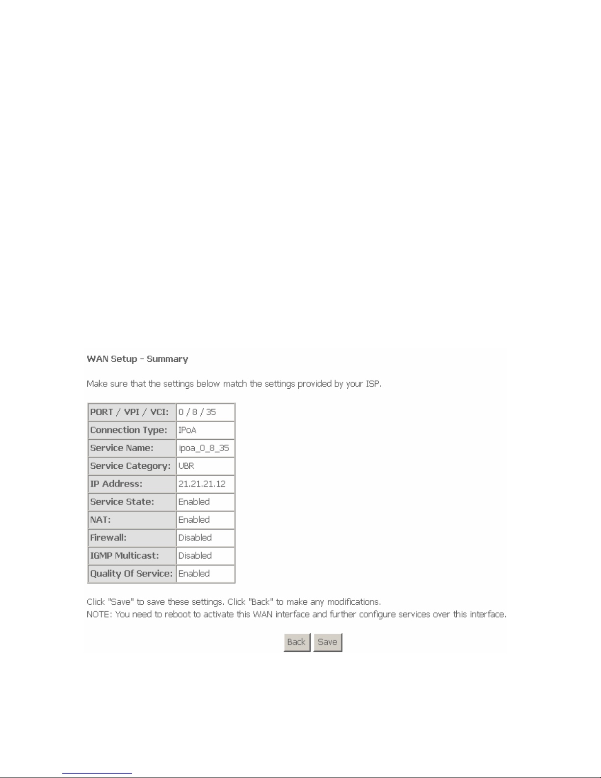
Click Next and the following page appears. This page shows all the
configuration.
To save the settings, click Save. To make any modifications, click Back.
Page 35
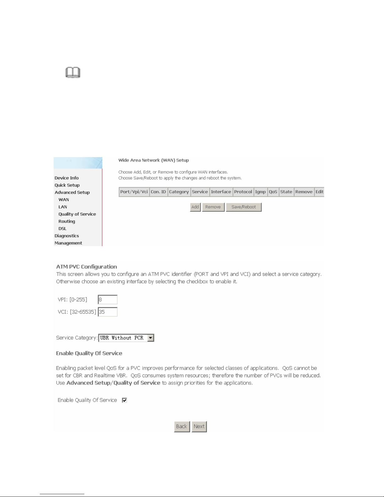
33
Note:
You need to reboot to the router to activate this WAN interface and further
configure services in this interface.
3.4.1.5 Adding a Bridge PVC
This section describes the procedure for adding PVC 8/35 (Bridge mode).
Click Add and the following page appears.
In this page, you can modify VPI/VCIs, service categories, and QoS.
Page 36
34
VPI (Virtual Path Identifier): Virtual path between two points in an ATM network.
Its valid value range is from 0 to 255.
VCI (Virtual Channel Identifier): Virtual channel between two points in an ATM
network. Its valid value range is from 32 to 65535 (1 to 31 are reserved for known
protocols).
Service Category: UBR Without PCR/UBR With PCR/CBR/Non Realtime
VBR/Realtime VBR.
Enable Quality Of Service: Enable or disable QoS.
In this example, PVC 8/35 is to be modified and the default values of service
category and QoS remain. In actual applications, you can modify them as
required.
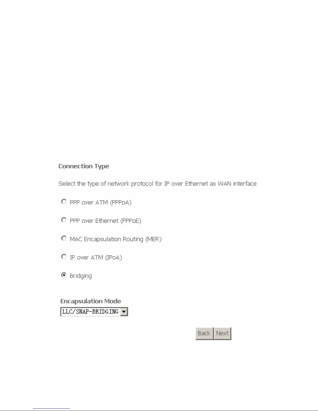
After proper modifications, click Next and the following page appears.
In this page, you can modify the Internet connection type and encapsulation type.
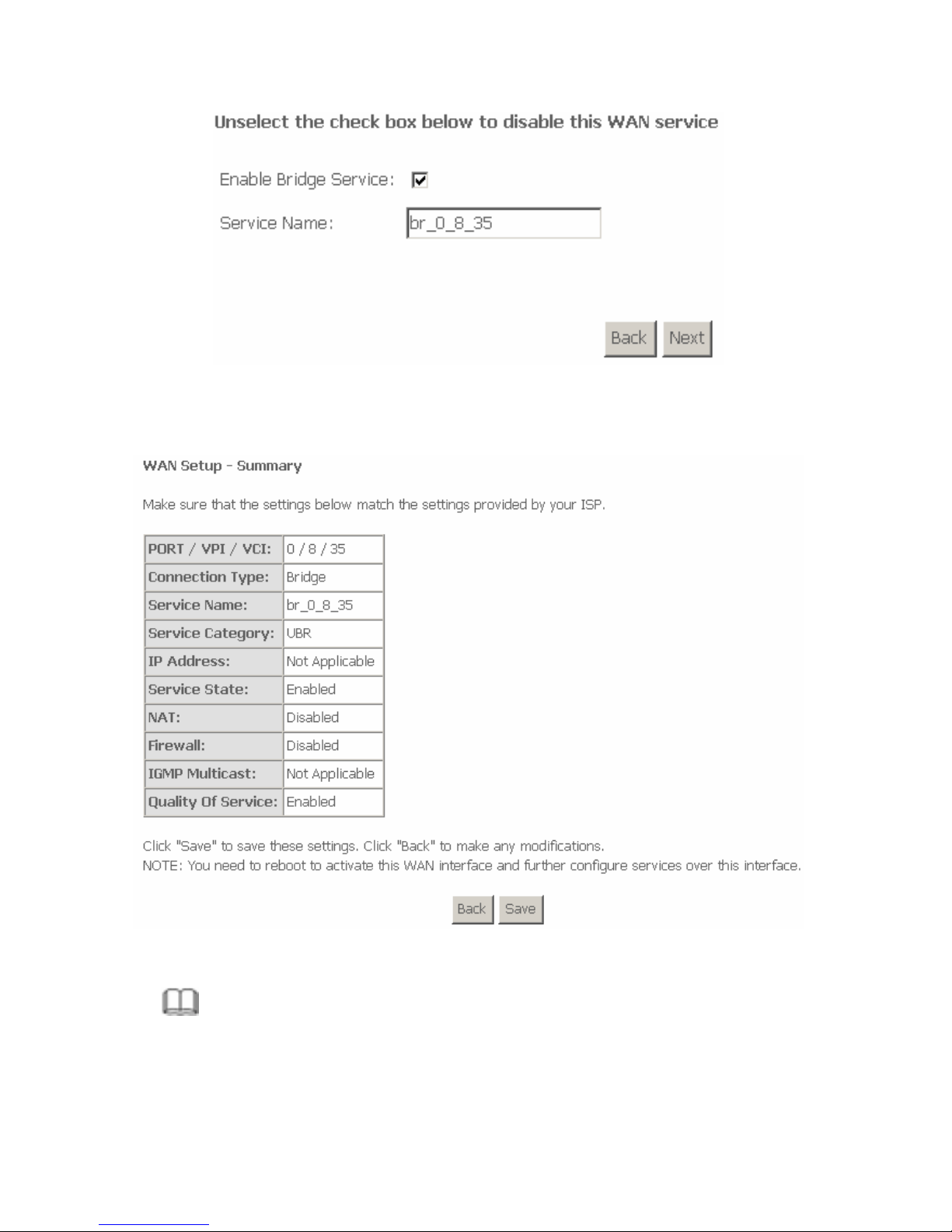
Click Next and the following page appears. In this page, you can modify the
service name.
Page 37
35
WAN Service: Enable it, unless you do not want to active the PVC.
Click Next and the following page appears. This page shows all the
configuration.
To save the settings, click Save. To make any modifications, click Back.
Note:
You need to reboot the router to activate this WAN interface and further
configure services in this interface.
Page 38
36
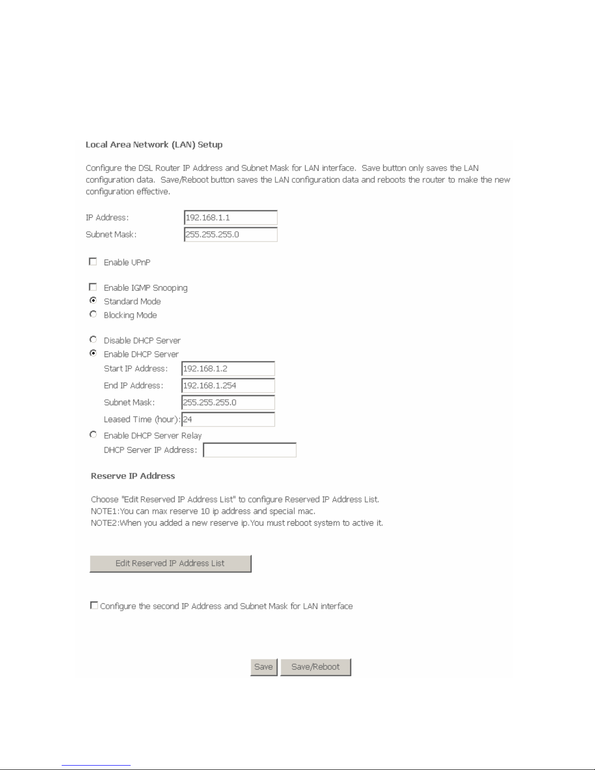
3.4.2 LAN Configuration
You can use the LAN configuration to define an IP address for the DSL Router
and configure the DHCP server.
Page 39
37
3.4.2.1 Defining the Private IP Address for the DSL Router
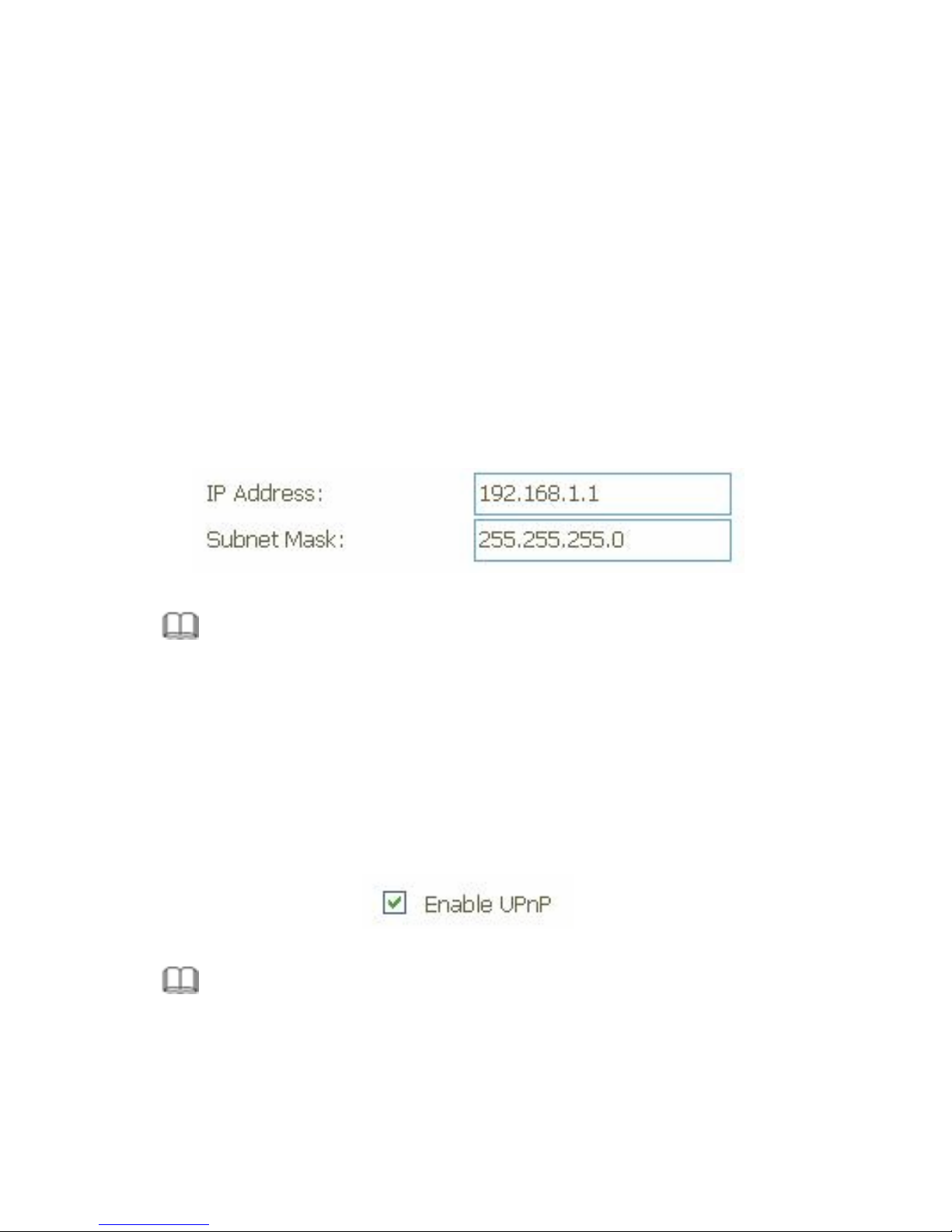
In this page, you can change the IP address of the device. The preset IP address
is 192.168.1.1. This is the private IP address of the DSL Router, under which the
device can be reached in the local network. It can be freely assigned from the
block of available addresses. The IP address under which the Router can be
reached from outside is assigned by the ISP.
If you want to assign a different IP address to the DSL Router, enter it in
the field next to IP address.
Adjust the subnet mask if necessary.
It is recommended to use an address from a block that is reserved for private
use.
The address block is 192.168.1.1~192.168.255.254.
Note:
New settings can only be made after the DSL Router is rebooted. If necessary,
reconfigure the IP address on your PC (including the one that is statically
assigned) so that it matches the new configuration.
3.4.2.2 Enabling UPNP
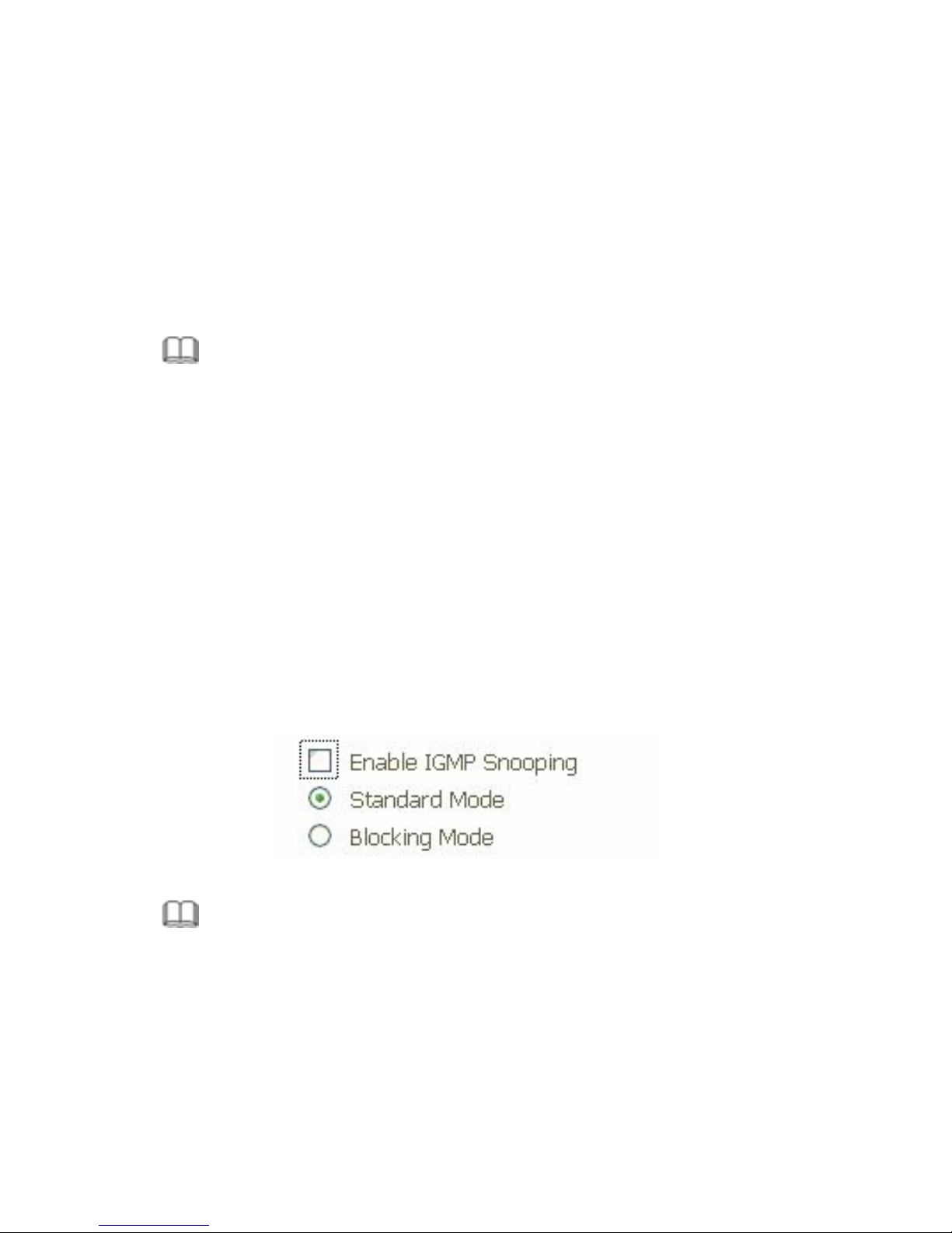
PCs with universal plug and Play (UPnP) can provide their own network services
and automatically use services provided in the network.
Note:
The operating system of the PC must be Windows ME or Windows XP. Check
whether the UPnP function is installed in the PC. You may need to
retrospectively install the UPnP components, even on systems with Windows
XP or Windows ME. Please refer to the User Guide of your PC.
Page 40
38
After you install UPnP in the operating system of a PC and activate it in the router,
applications on this PC (for example, Microsoft Messenger) can communicate via
the Internet without authorization. In this case, the router automatically
implements port forwarding, thereby facilitating communication via the Internet.
The task bar in the PC in which UPnP is installed contains an icon for the DSL
Router. In a Windows XP system, the icon is also shown under network
connections. Click this icon and the user interface of the DSL Router appears.
Note:
When the UPnP function is active, system applications can assign and use
Ports on a PC. This poses a security risk.
3.4.2.3 Enabling IGMP Snooping
Internet Group Management Protocol
IGMP is an Internet protocol that enables an Internet computer to inform
neighboring routers that it is a member of a multicast group. With multicasting, a
computer can send content on the Internet to several other computers that have
registered an interest in the content of the first computer. Multicasting can, for
example, be used for multimedia programs for media streaming to recipients that
have set up multicast group membership.
Note:
If IGMP snooping function is enabled, the DSL Router capability improves.
Page 41
39
3.4.2.4 Configuring the DHCP Server
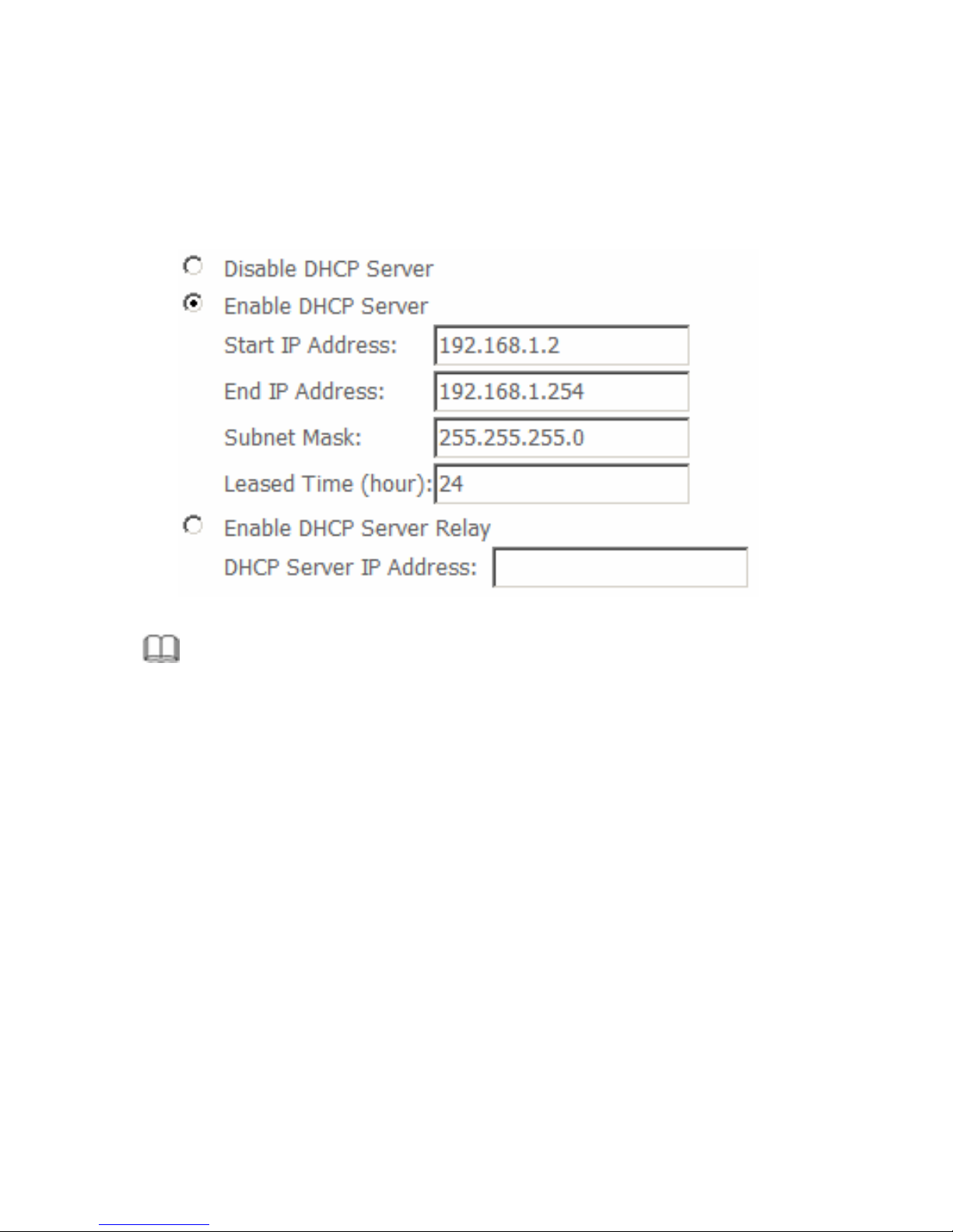
The DSL Router has a DHCP server for which the factory setting is active.
Consequently, the IP addresses of the PCs are automatically assigned by the
DSL Router.
Note:
If the DHCP server for the DSL Router is activated, you can configure the
network setting on the PC so that the option Obtain an IP address
automatically is set up.
If you deactivate the DHCP server, you need to assign a static IP address
for the PCs that use the network settings.
If the DHCP server is active, you can define a lease time. The lease time
determines the period for which the PCs retain the IP addresses assigned
to them without changing them.
Define the range of IP addresses that the Router should use to
automatically assign IP addresses to the PCs. Define the first issued IP
address and the last issued IP address.
Enable DHCP Server Relay: This function allows you to relay DHCP and
BOOTP requests from a subnet with no DHCP server on it to one or more
DHCP servers on other subnets.
Page 42
40
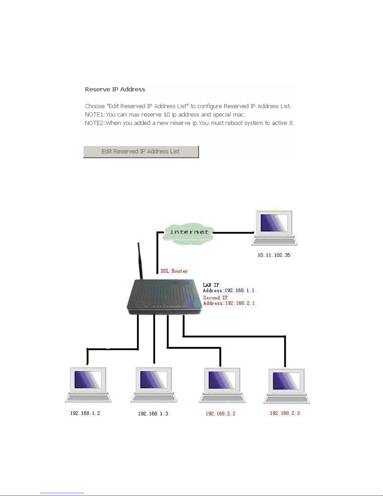
3.4.2.5 Reserve IP Address
If you want to reserve one specific IP address for a certain PC by MAC address,
edit the reserved IP Address List.
3.4.2.6 Configuring the Second IP Address and Subnet Mask for
LAN Interface
Page 43
41
3.4.3 NAT
Note:
The NAT information is not displayed in the bridge mode.
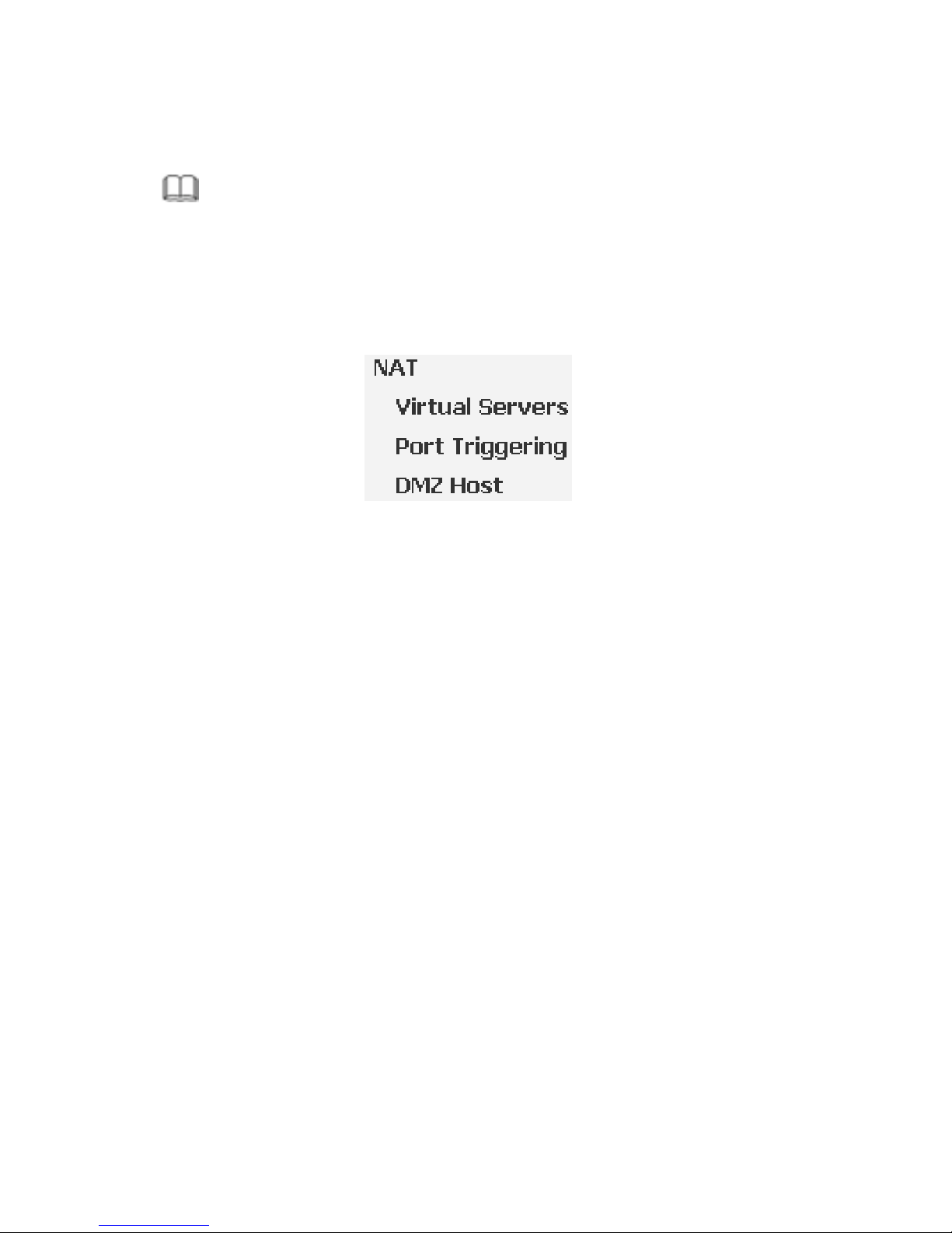
Click Advanced Setup > NAT, and the following page appears. This part
contains Virtual Servers, Port Triggering, and DMZ Host. Choose the item to do
relative configurations.
3.4.4 Security
Security is an important function of DSL. It protects resources of a private
network from users from other networks, and prevents unauthorized Internet
users from accessing private networks connected to the Internet. All messages
entering or leaving the intranet (that is, the local network to which you are
connected) must pass through the security checks, which checks each message
and blocks those that do not meet the specific security criteria.
There are two basic types of security techniques:
IP packet filtering: The system checks each packet entering or leaving
the network and accepts or rejects it based on user-defined rules. Packet
filtering is fairly effective and transparent to users, but is difficult to
configure.
Parental Control: The system checks each frame entering or leaving the
network from layer 2. It accepts and rejects frames according to
user-defined rules.
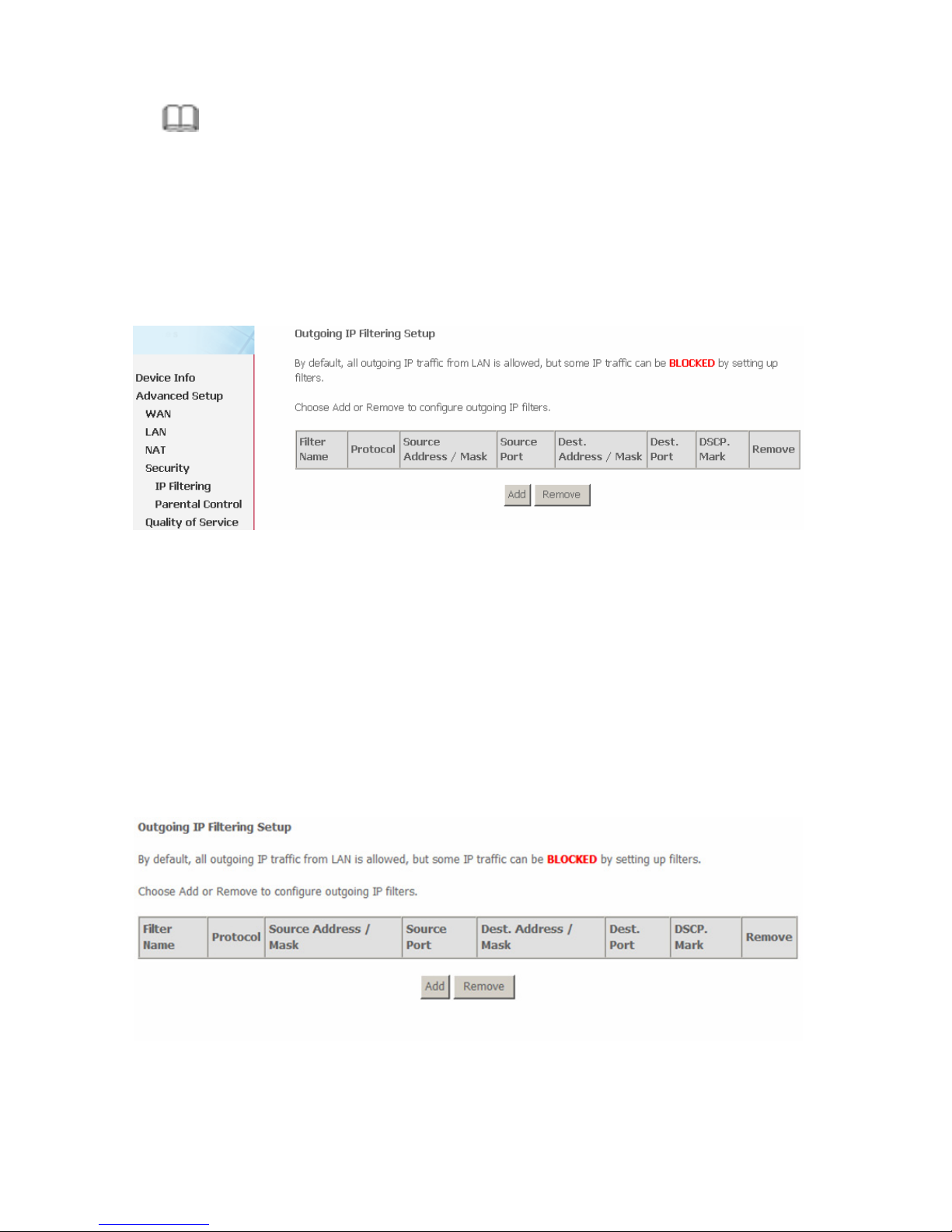
Choose Security > IP Filtering and the following page appears. By default, the
firewall is enabled. The firewall is used to block document transmissions between
the Internet and your PC. It serves as a safety guard and permits only authorized
documents to be sent to the LAN.
Page 44
42
Note:
If the router is configured to bridge mode only, IP filtering is disabled and the
IP filtering interface does not appear.
If no PVC of Bridge mode is configured, MAC filtering is disabled and the
MAC Filtering interface does not appear.
3.4.4.1 Outgoing IP Filtering Setup
When setup of outgoing IP filtering rules is enabled on the router, various security
functions for the local network are enabled at the same time. You can protect the
network against hacker attacks and block access of individual PC to selected
services or Internet websites.
Choose Security > IP Filtering > Outgoing and the following page appears.
By default, all outgoing IP traffic from LAN is allowed, but some IP traffic can be
blocked by setting up filters.
Page 45
43
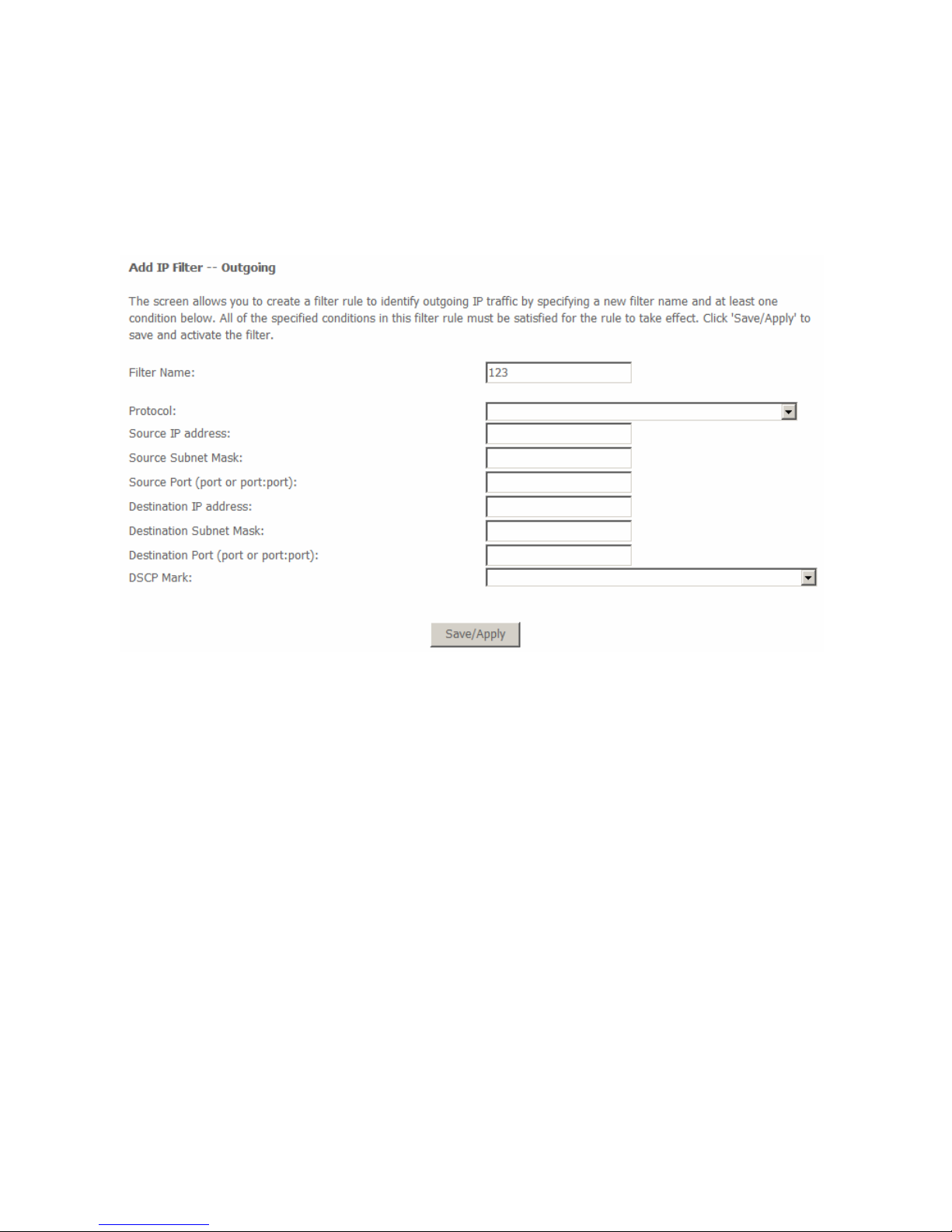
Click Add and the page for defining the IP filtering rule appears.
In this page, you can create a filter rule to identify outgoing IP traffic by specifying
a new filter name and at least one condition. All specified conditions in the
filtering rule must be complied with the rule to take effect.
Click Save/Apply to save and activate the filter.
Filter Name: Enter the name of outgoing filter rule.
Protocol: Select one from TCP/UDP, TCP, UDP, and ICMP protocols.
Source IP address: Enter an IP address. After you set the IP address,
outgoing packets (protocol selected packets) are blocked.
Source port: UPD/TCP source port or a range of ports.
Destination IP address: IP address of the destination (default: null).
Destination port: UPD/TCP destination port or a range of ports.
DSCP Mark: Marking DSCP that outgoing packets.
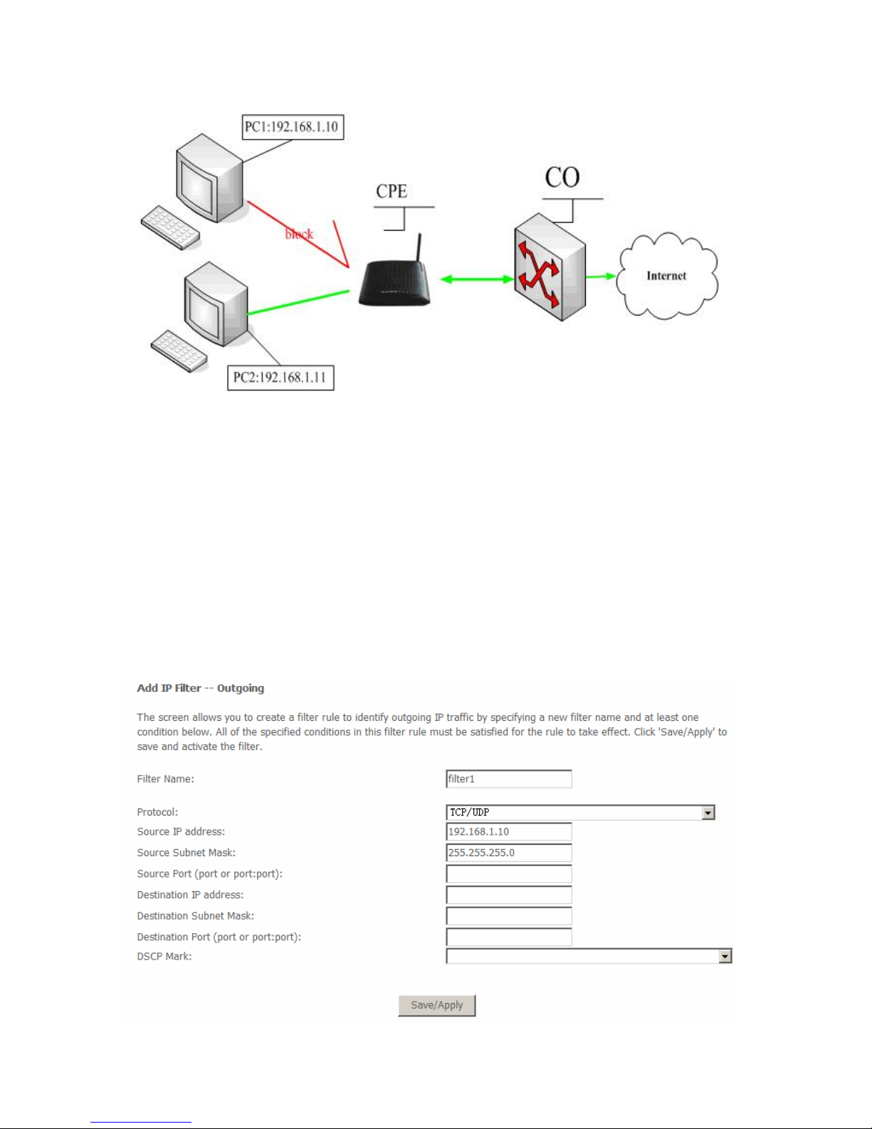
The following is an example of configuring the outgoing IP filtering.
The topology is as follows:
Page 46
44
Request
I need to block PC1 whose IP address is 192.168.1.10. All outgoing
UDP/TCP packet from that PC1 (192.168.1.10) is not allowed.
Allow all outgoing traffic packet from PC2 (192.168.1.11).
Configuration
Step 1 By default, all outgoing IP traffic from LAN is allowed. Hence, all outgoing
IP packets from PC2 are allowed. The detailed configuration steps are as
follows:
Page 47
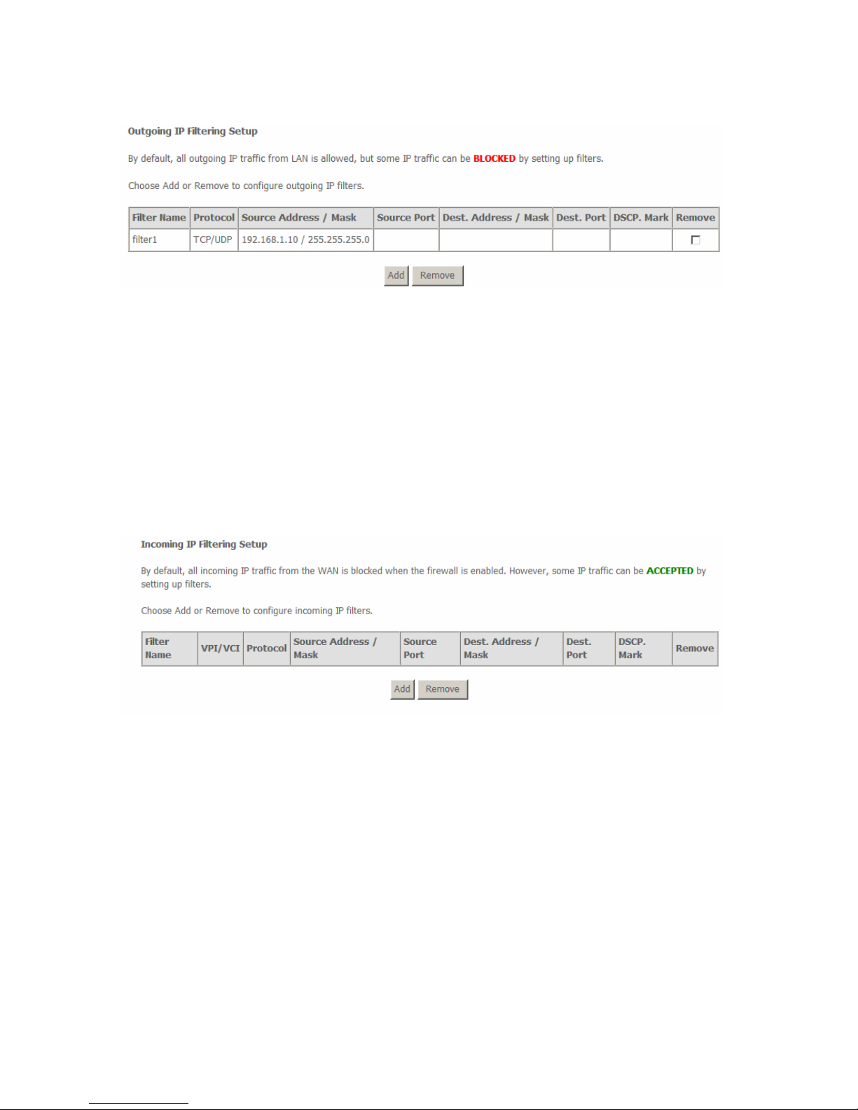
45
Step 2 Click Save/Apply and the following page appears:
3.4.4.2 Incoming IP Filtering Setup
The incoming IP filter is used to block and permit IP packet transmisstion from
internet. By default incoming IP filter block all incoming packet from Internet.
When incoming IP filtering rules setup being enable on the router, you can permit
remote individual PC to access various local network service.
Choose Security > IP Filtering > Incoming and the following page appears.
By default, all incoming IP traffic from the WAN is blocked when the firewall is
enabled. However, some IP traffic can be accepted by setting up filters.
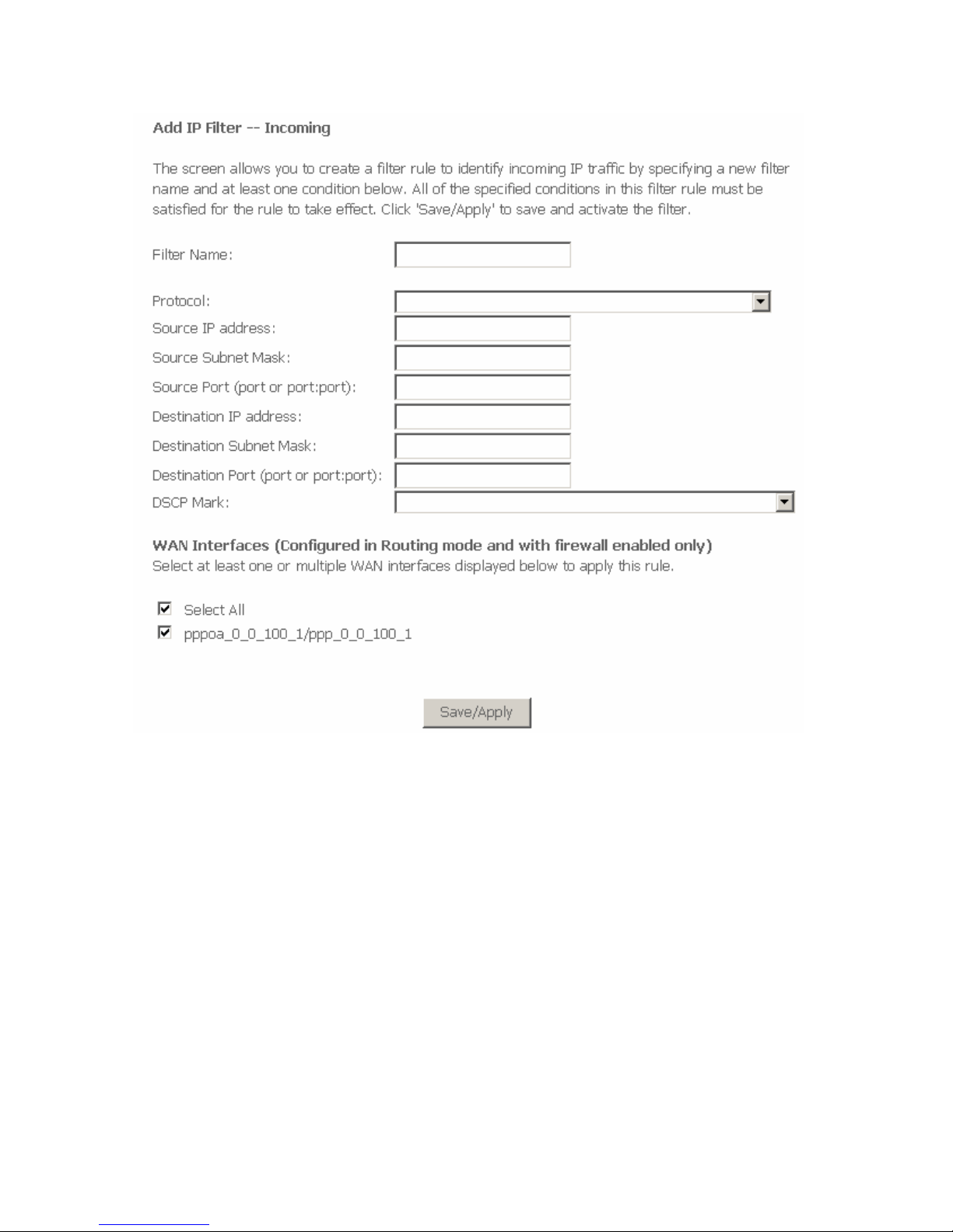
Click Add and the page for defining the IP filtering rule appears.
In this page, you can create a filter rule to identify incoming IP traffic by specifying
a new filter name and at least one condition. All specified conditions in the filter
rule must be complied with the rule to take effect. Click Save/Apply to save and
activate the filter.
You must select at least one WAN interface to apply this rule.
Page 48
46
Filter Name: Enter the name of incoming filter rule.
Protocol: Select one from TCP/UDP, TCP, UDP, and ICMP protocols.
Source IP address: Enter an IP address. After you set the IP address, the
incoming packets (protocol selected packets) are allowed.
Source port: UPD/TCP source port or a range of ports.
Destination IP address: destination IP (default: null).
Destination port: UPD/TCP destination port or a range of ports.
DSCP Mark: Marking DSCP that outgoing packets.
WAN interfaces: You can select WAN interfaces and PVC.
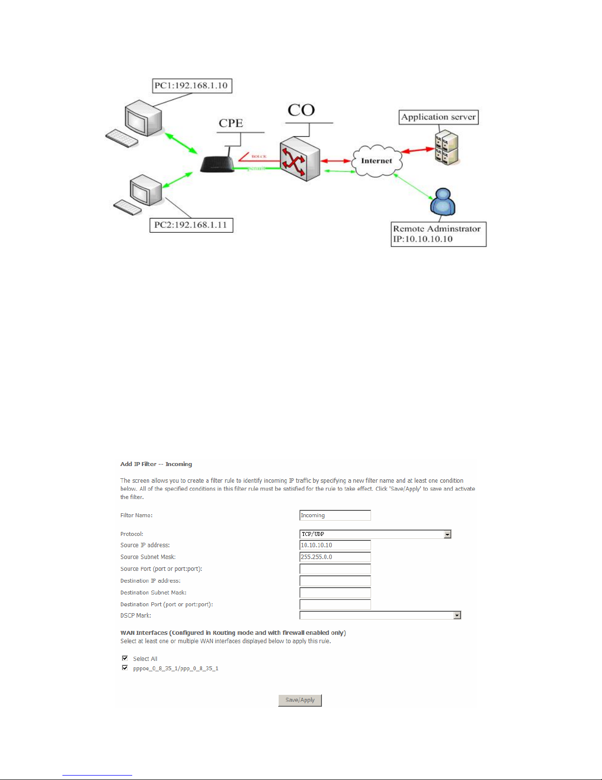
The following is an example of configuring the incoming IP filtering:
Page 49
47
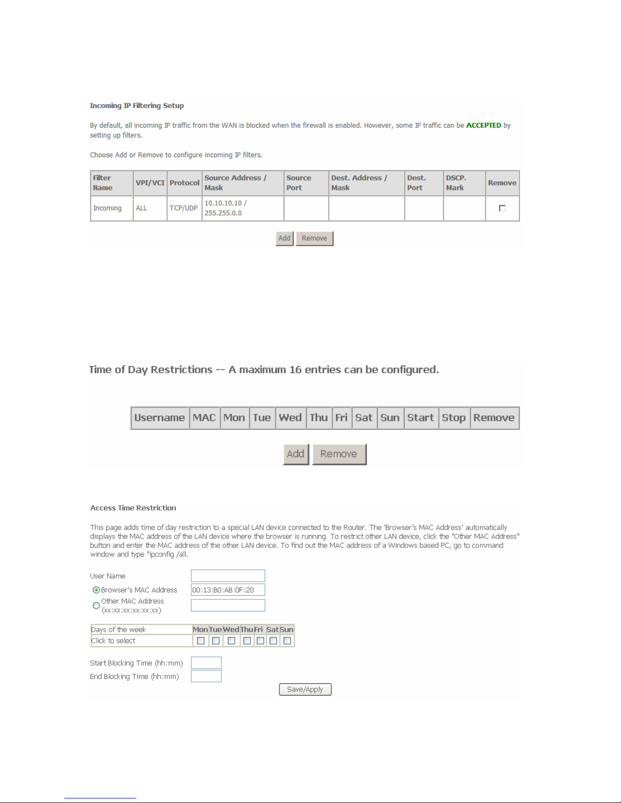
Request
I need to permit a PC whose IP address is 10.10.10.10. All Incoming
TCP/UDP packet traffic from that PC (10.10.10.10) is allowed.
Block all IP traffic from other PCS.
Configuration
Step 1 By default, all incoming IP traffic from Internet is blocked. Hence, all
incoming IP packets from other PCS except PC (10.10.10.10) are
blocked.
Step 2 The detailed configuration steps are as follows:
Page 50
48
Step 3 Click Save/Apply and the following page appears:
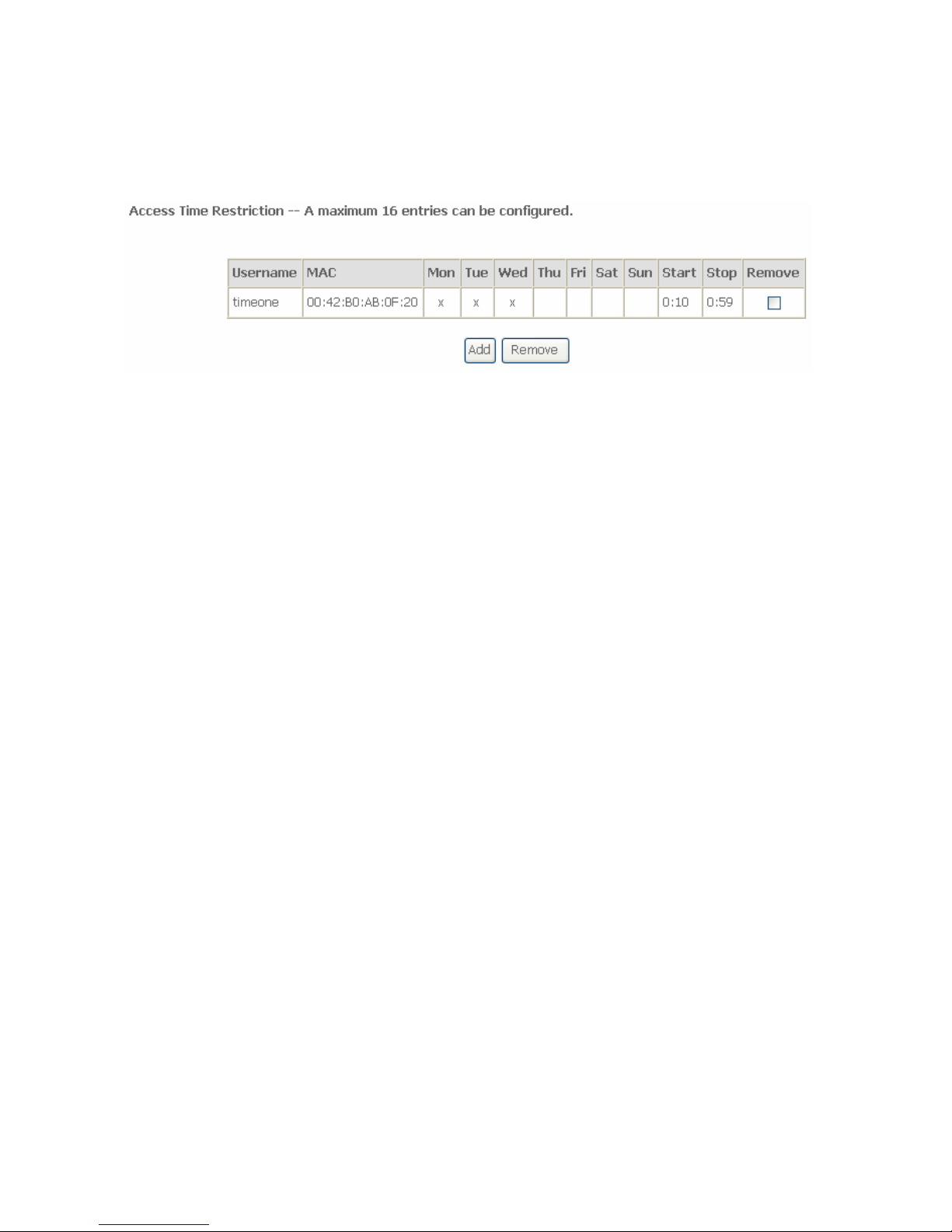
3.4.4.3 Parental Control
If you allow your children to access to the Internet in the specific time, add the
schedule with the LAN MAC address of the device. Choose Security > Parental
Control and the following page appears.
Click Add and the following page appears:
Page 51
49
In this page, you can add time of day restriction to a specific LAN device
connected to the Router. Enter the user name, select days of week and the
blocking time, and click Save/Apply. The following page appears:
3.4.5 Quality of Service
Many communication and multimedia applications require large, high speed
bandwidths to transfer data between the local network and the Internet. However,
for many applications there is often only one Internet connection available with
limited capacity. QoS divides this capacity between the different applications and
provides undelayed and continuous data transfer where data packets with higher
priority are given preference.
Click Quality of Service and the following page appears. Under Quality of
Service, there are two network share modes: Queue Config and QoS
Classification.
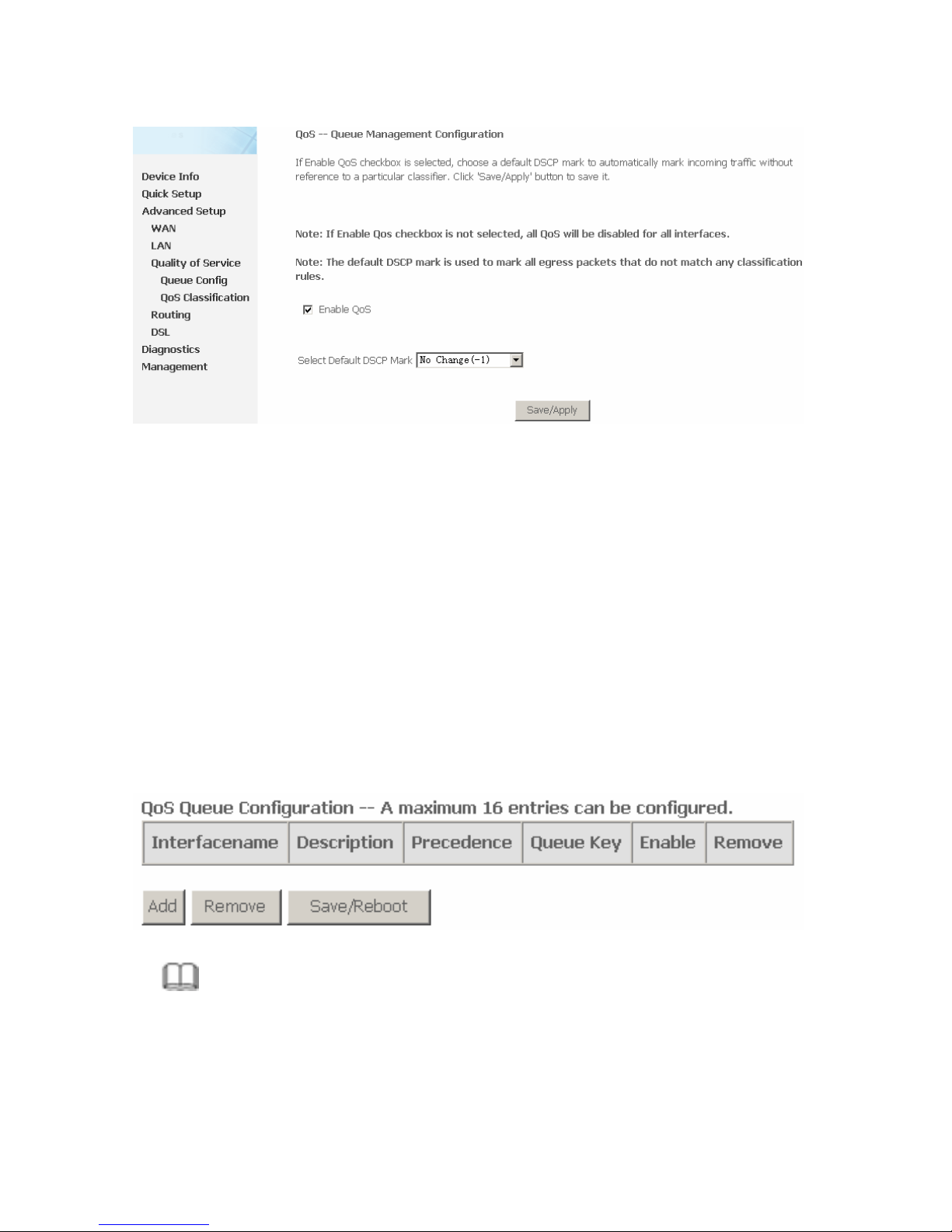
3.4.5.1 Enabling QoS
In this page, you can configure QoS queue management. By default, the system
enables QoS and sets a default DSCP mark to automatically mark incoming
traffic without reference to particular classifier.
Choose Advance Setup > Quality of Service and the following page appears:
Page 52
50
Select Enable QoS to enable QoS and set the default DSCP mark.
Click Save/Apply to active QoS.
3.4.5.2 QoS - Queue Configuration
The queuing in packet QoS becomes effective only when packet is forwarded to
QoS-enabled PVC. Packet forwarding is determined by IP routing or bridging, not
under control of the packet QoS.
Click Queue Config and the following page appears. In this page, you can
configure QoS Queue. A maximum of 24 entries can be configured.
QoS Queue Configuration can allocate three queues. Each of the queues can be
configured for a precedence value. The queue entry configured is used by the
classifier to place ingress packets appropriately.
Note:
Lower integer values for precedence indicate higher priority for this queue
relative to others.
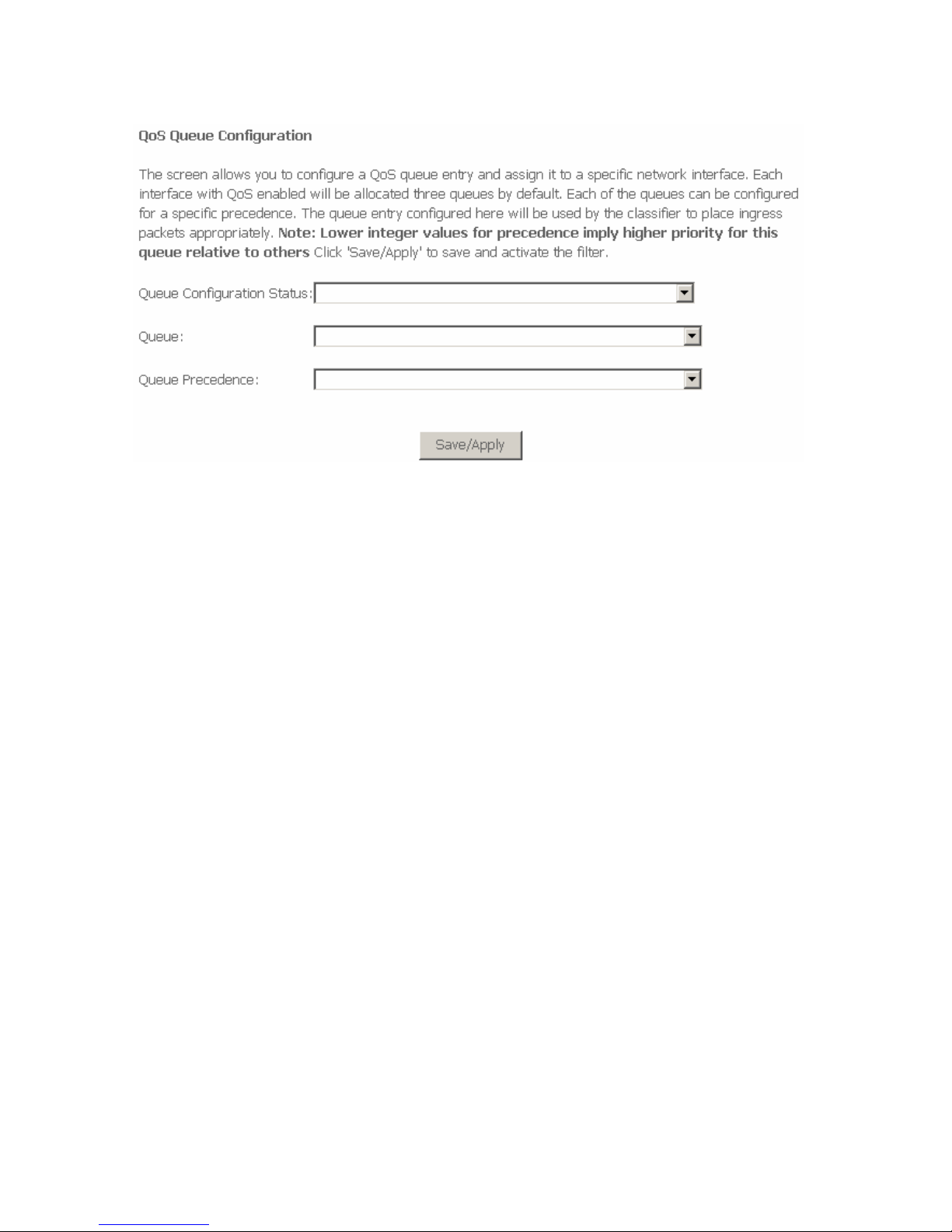
Click Add and the following page appears.
Page 53
51
Queue Configuration Status: Set to enable or disable a QoS queue.
Queue: Select a specific network interface. The router automatically allocates
selected network interface to the queue.
Queue Precedence: Select an integer value for queue precedence. After you
select an integer value, the queue entry appropriately places to ingress packets.
Lower integer values for precedence imply higher priority for this queue relative
to others.
3.4.5.3 QoS - QoS Classification
Some applications require specific bandwidth to ensure their data be forwarded
in time. QoS classification can creates traffic class rule to classify the upstream
traffic. Assign queue which defines the precedence and the interface and
optionally overwrite the IP header DSCP byte. After QoS classification, QoS
divides capacity between different applications and provides undelayed and
continuous data transfer where data packet with higher priority is given
preference.
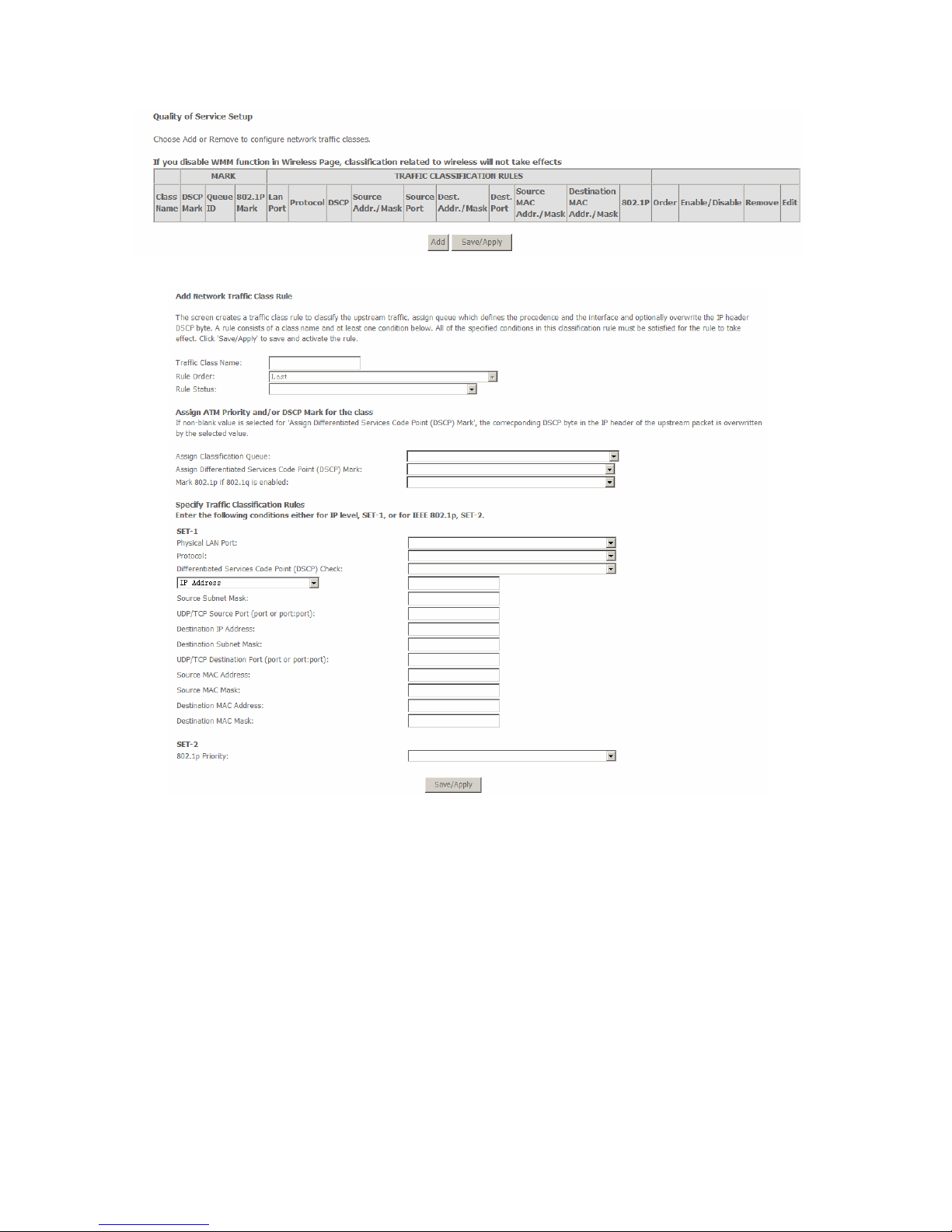
Click QoS Classification and the following page appears. In this page, you can
configure network traffic classes.
Page 54
52
Click Add, and the following page appears.
Traffic Class Name: Enter a name of the class.
Rule Order: Select order for queue.
Rule Status: Enable or disable this traffic class rule.
Assign Classification Queue: Select a classification queue.
Assign Differentiated Service Code Point (DSCP) Mark: Select a mark
service that modifies the original packet IP header if all rules defined within
the classification class are matched. (CS - Mark IP Precedence, AF -
Assured Forwarding, EF - Expedited Forwarding)
Mark 802.1p if 802.1q is enabled: Select an 802.1p priority number that
serves as the 802.1p value.
Page 55
53
There are two sets of classification rules. Set-1 is based on different fields within
TCP/UDP/IP layer plus physical LAN port; Set-2 is based on MAC layer IEEE
802.1p priority field.
802.1p priority: The 802.1p header includes a 3-bit prioritization field, which
allows packets to be grouped into eight levels of priority (0-7), where level 7 is the
highest one.
3.4.6 Routing
3.4.6.1 Routing – Default Gateway
In this page, you can modify the Default Gateway settings.
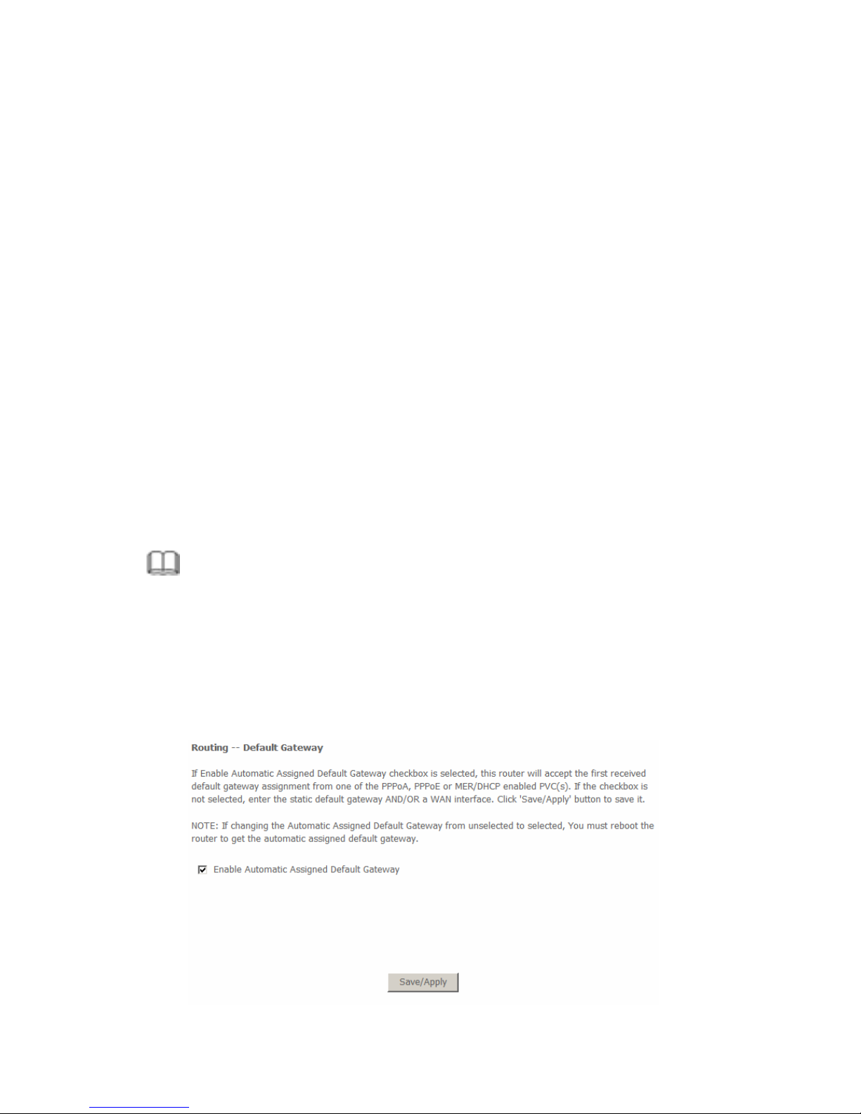
If the Enable Automatic Assigned Default Gateway checkbox is selected, this
router accepts the first received default gateway assignment from one of the
PPPoA, PPPoE or MER/DHCP enabled PVC(s). If the checkbox is not selected,
enter the static default gateway and/or a WAN interface. Click Save/Apply to
save it.
Note:
After changing the Automatic Assigned Default Gateway from unselected
to selected, you must reboot the router to obtain the automatic assigned
default gateway.
If you want to use a default gateway, select the Enable Automatic Assigned
Default Gateway check box to show the following page:
Page 56

54
Use Default Gateway: Select the Enable automatic Assigned Default Gateway
box.
Custom DSL router Default Gateway
Enable Automatic Assigned Default Gateway
Use Default Gateway IP Address
Use Interface: interface that the packets pass through on the router
Click Save/Apply to apply the settings.
3.4.6.2 Static Routes
Networking devices forward packets using route information that is either
manually configured or dynamically learned using a routing protocol. Static routes
are manually configured and define an explicit path between two networking
devices. Unlike a dynamic routing protocol, static routes are not automatically
updated and must be manually reconfigured if the network topology changes.
The benefits of using static routes include security and resource efficiency. Static
routes use less bandwidth than dynamic routing protocols and no CPU cycles are
used to calculate and communicate routes. The main disadvantage to using
static routes is the lack of automatic reconfiguration if the network topology
changes.
Static routes can be redistributed into dynamic routing protocols but routes
generated by dynamic routing protocols cannot be redistributed into the static
routing table. No algorithm exists to prevent the configuration of routing loops that
use static routes.
Static routes are useful for smaller networks with only one path to an outside
network and to provide security for a larger network for certain types of traffic or
links to other networks that need more control. In general, most networks use
dynamic routing protocols to communicate between networking devices but may
have one or two static routes configured for special cases.
Page 57
55
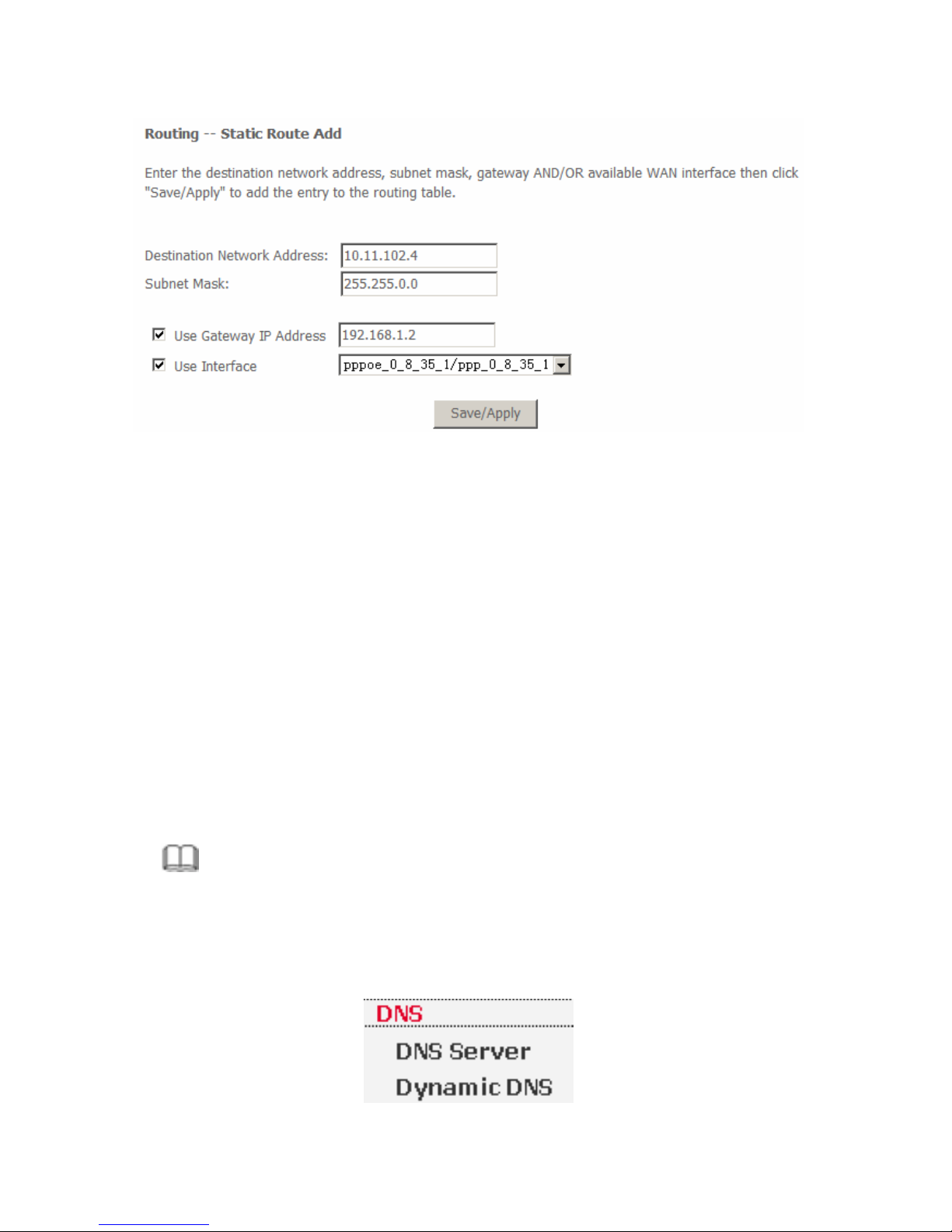
Adding Static Route
Step 1 Enter destination network address.
Step 2 Enter subnet Mask.
Step 3 Enable Use Gateway IP Address and enter IP address.
Step 4 Select use interface.
Step 5 Click Save/Apply to apply the settings.
Remove static route
Select Remove box in the table, and click Remove to apply the settings.
3.4.7 DNS
Note:
If the connection is Bridge PVC, you can not view the DNS item.
Click Advanced Setup > DNS, and the following page appears. Choose the item
to do relative configurations.
Page 58
56
3.4.8 DSL
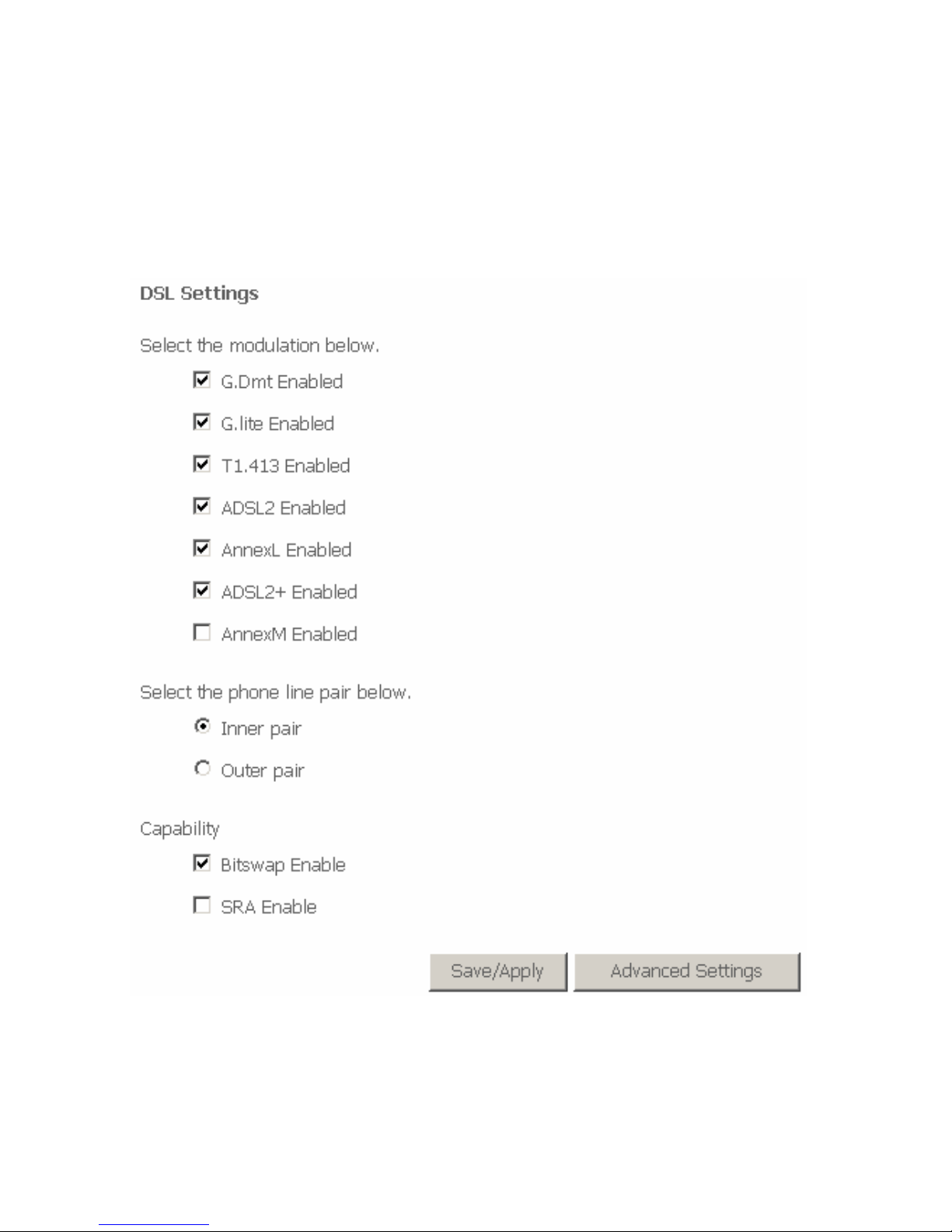
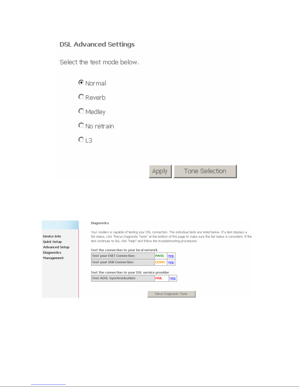
In this interface, you can view the DSL settings. Normally, you can keep the
factory default settings. The router support these modulations: G.Dmt, G.lite,
T1.413, ADSL2, AnnexL, ADSL2+ and AnnexM. The router negotiates the
modulation mode with the DSLAM.
Click Advanced Settings, and the following page appears.
Page 59
57
3.5 Diagnostics
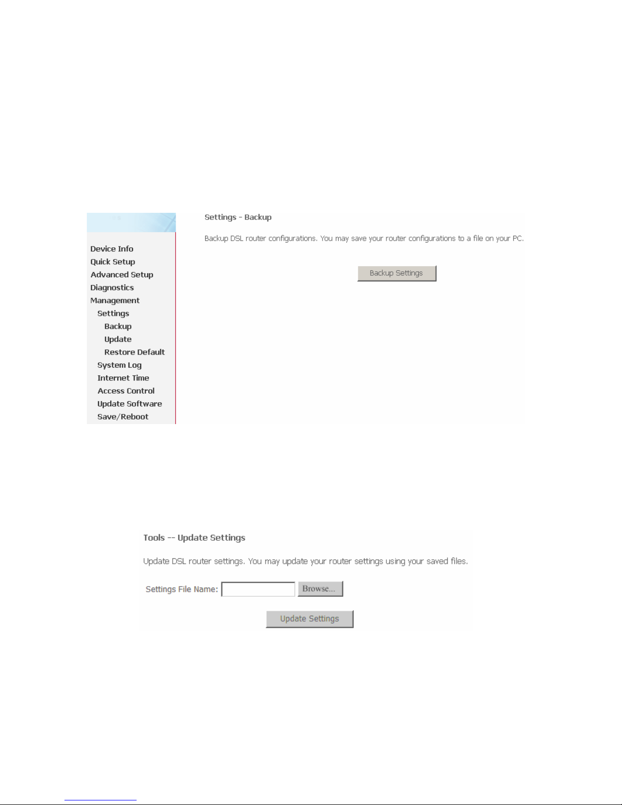
Click Diagnostics, and the following page appears.
Your router is capable of testing your DSL connection. The individual tests are listed
above. If a test displays a fail status, click Rerun Diagnostic Tests at the bottom of
this page to make sure the fail status is consistent. If the test continues to fail, click
Help and follow the troubleshooting procedures.
Page 60
58
3.6 Management
3.6.1 Setting
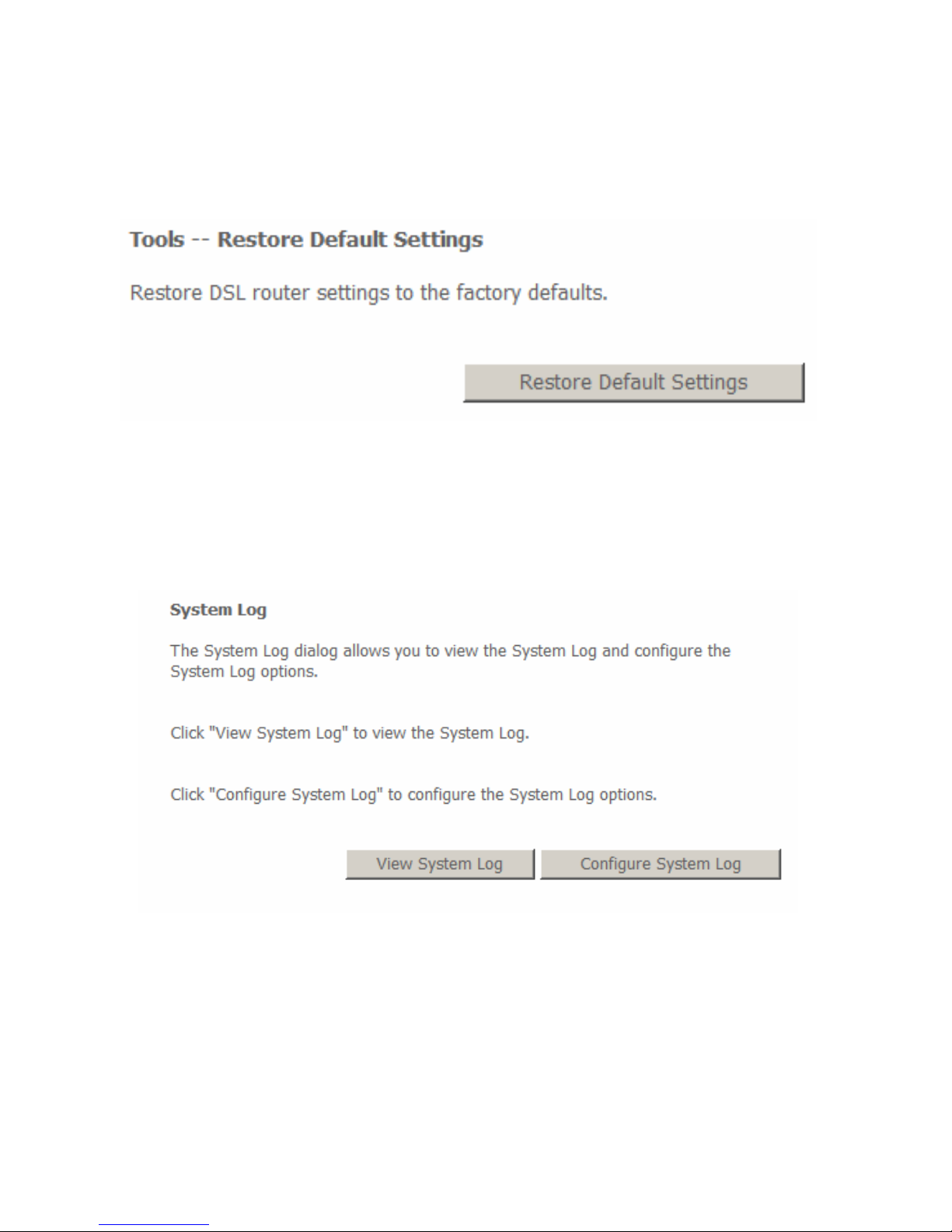
Settings - Backup
Select the “Backup” to show the following interface. In the interface, you can
backup the DSL router configurations.
Settings - Update
Select the “Update” to show the following interface. Click the “Browsing...” button
to select the correct update configure settings file. Then click the “Update
Settings” to update the router settings.
Page 61
59
3.6.1.1 Settings Restore Default
Click Management > Settings > Restore Default to restore DSL router to the
factory default configuration.
3.6.2 System Log
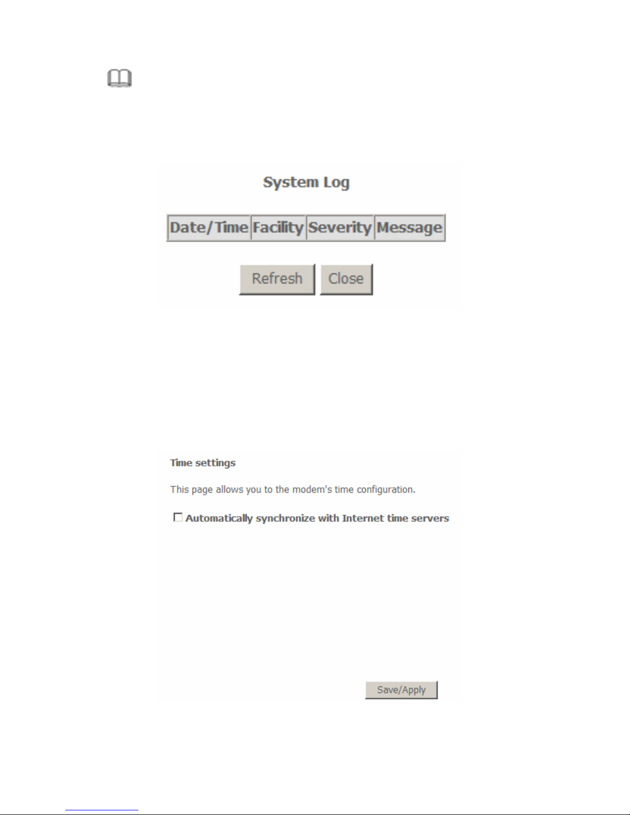
Click Management > System Log, and the following page appears. The system
log dialog allows you to view the system log and configure the system log
options.
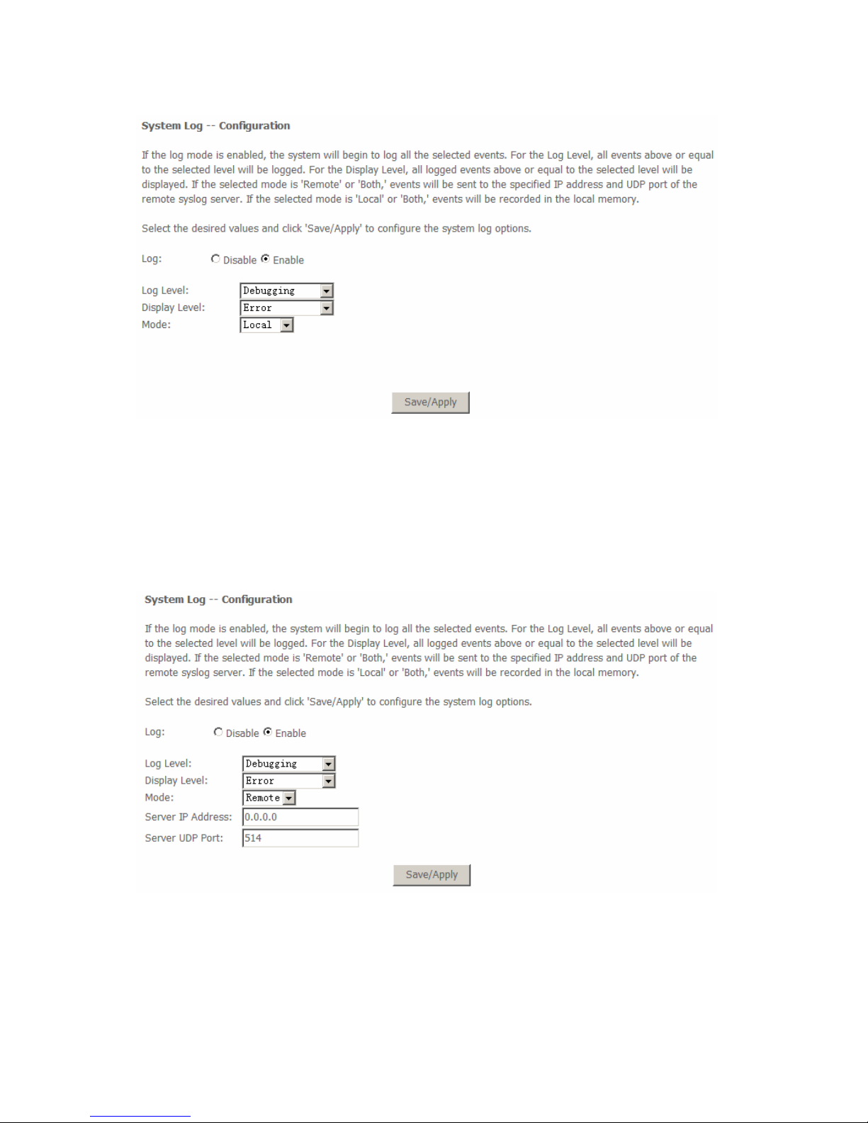
Click “Configure System Log” to show the following interface. You can enable or
disable the system log and then select the log level, display level and mode, and
click “Apply” to end your configurations.
Page 62
60
Both the log level and display level have eight choices. The default log level is
“Debugging” and the default display level is “Error”.
The mode options are “Local”, “Remote”, and “Both”. The default option is
“Local”.
If you select “Remote” or “Both”, all events are transmitted to the specified UDP
port of the specified log server.
After operations under “Configure System Log”, click “View System Log” to query
the system logs.
Page 63
61
Note:
The log and display of the system events are above the set level. If you intend
to record all information, you need to set the levels as “Debugging”.
Click “Refresh” to refresh the system event logs or “Close” to exit from this
interface.
3.6.3 Internet Time
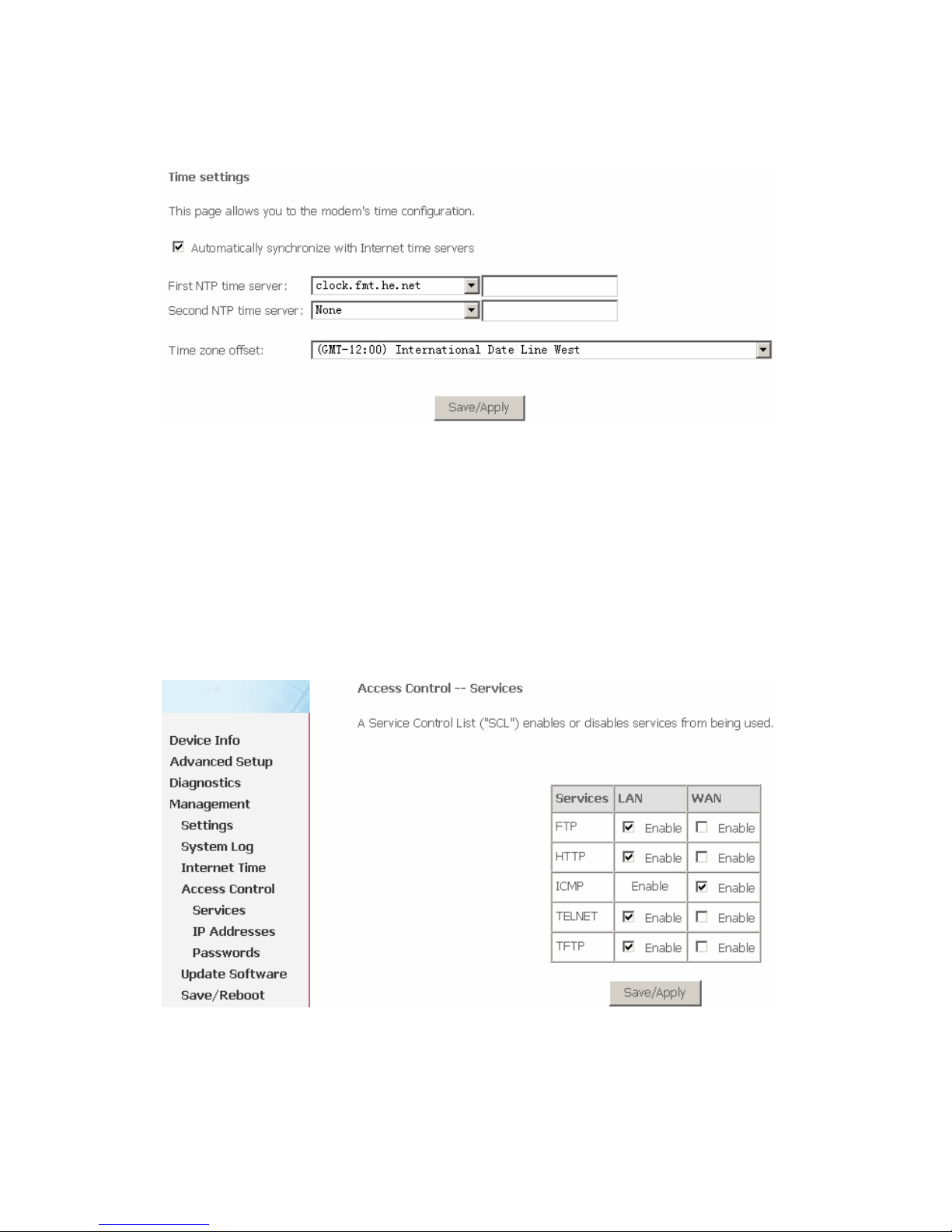
Click Management > Internet Time, and the following page appears. In this
page, the router can synchronize with Internet time servers.
Page 64
62
After enable Automatically synchronize with Internet time servers, the
interface show below. Enter proper configurations and click Save/Apply.
3.6.4 Access Control
Access Control – Services
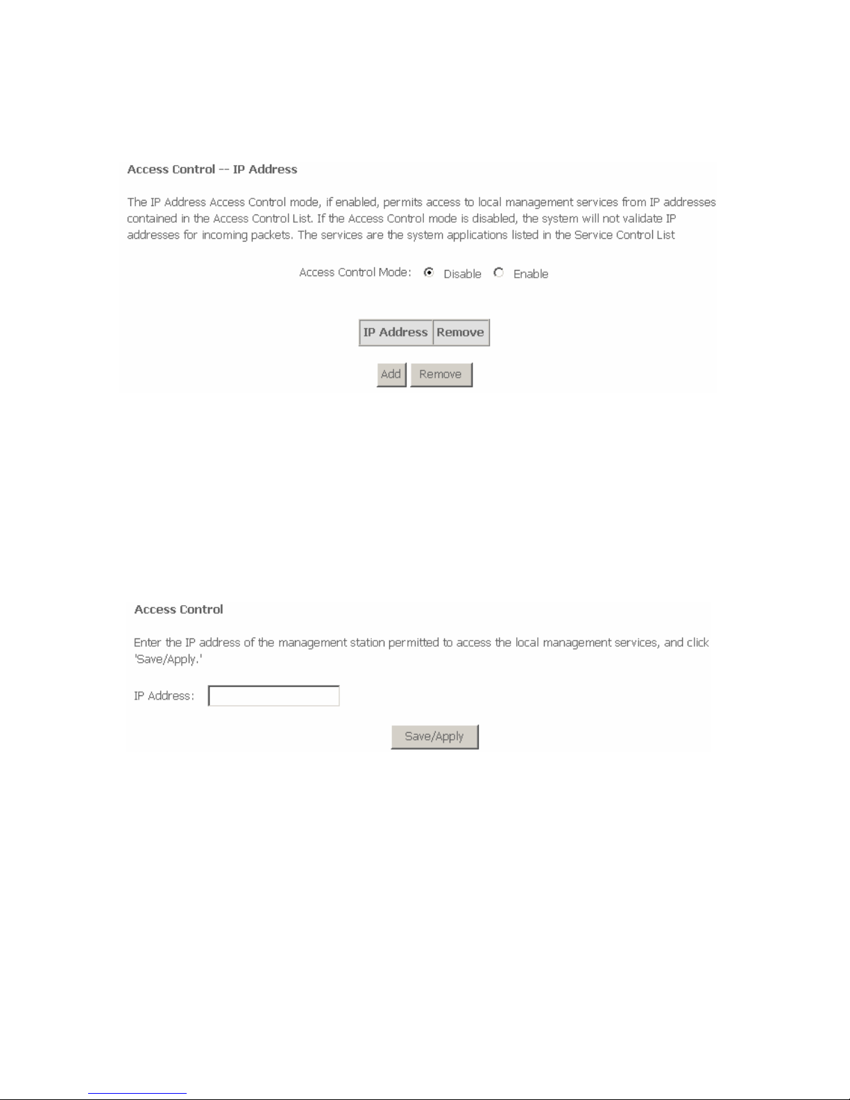
Select “Access Control”-->”Services” to show the following interface. In the
interface, you can enable/disable the FTP, HTTP, ICMP, TELNET and TFTP
services. And the LAN side and WAN side show different configurations.
Note:
The WAN information is not displayed in the bridge mode.
Page 65
63
Access Control – IP Addresses
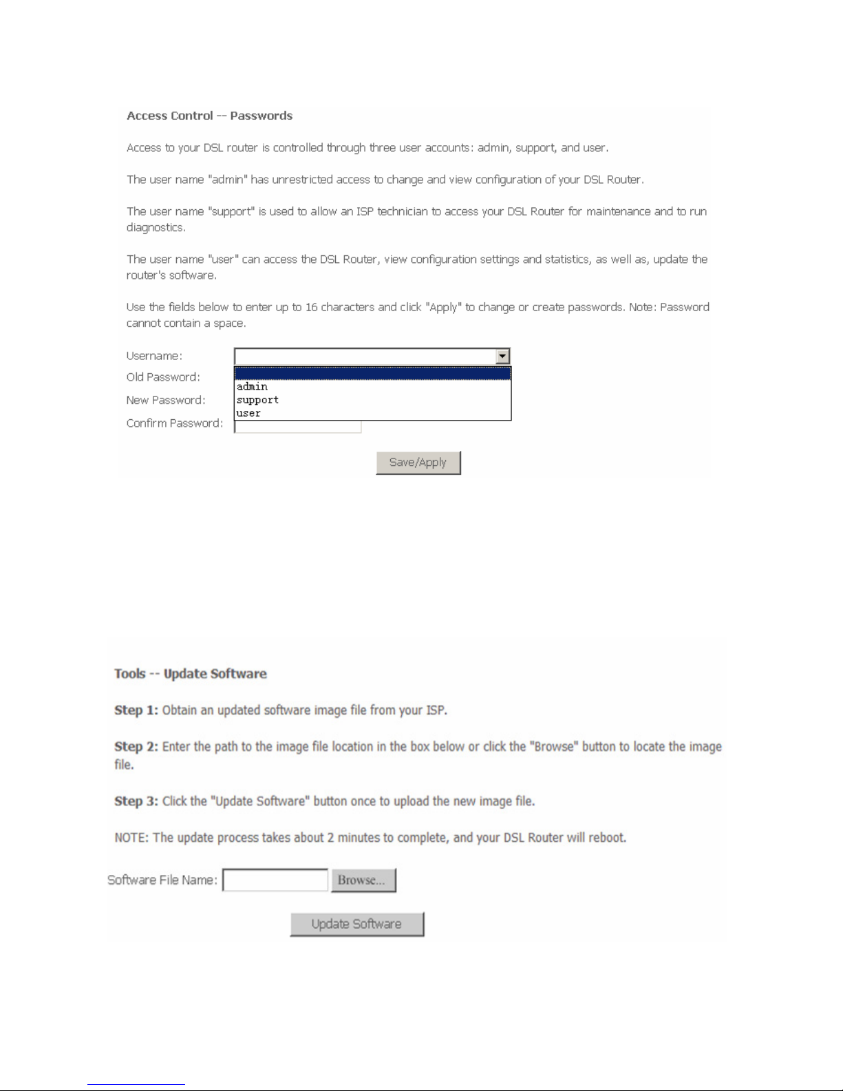
Choose Access Control > IP Addresses and the following page appears.
In this page, you can add or remove the IP address in the IP access control list.
If the Access Control Mode is enabled, it indicates that the router permits the
access to local management services from the IP addresses contained in the
access control list.
If the Access Control Mode is disabled, the system does not validate IP addresses
for the incoming packets.
Click the Add button to display the following page.
In this page, enter the IP address of the management station permitted to access
the local management services, and then click Save/Apply.
Access Control – Passwords
Click “Access Control”-->”Passwords” to show the following interface. In the
interface, you can modify the accounts passwords.
Page 66
64
3.6.5 Update Software
Click “Update Software” to show the following interface. In this interface, you can
update the router software. Click the “Browse...” button to find the right version
file and press “Update Software” to do the update.
Page 67
65
Note:
Do not turn off your router during firmware updates. When the update is
finished, the router reboots automatically. Do not turn off your router before
the reboot is over. You must guarantee the update software is right and
accurate. It is strictly forbidden to use other software for updates.
After update software, it is suggested to restore the router to the factory defaults
and configure it again.
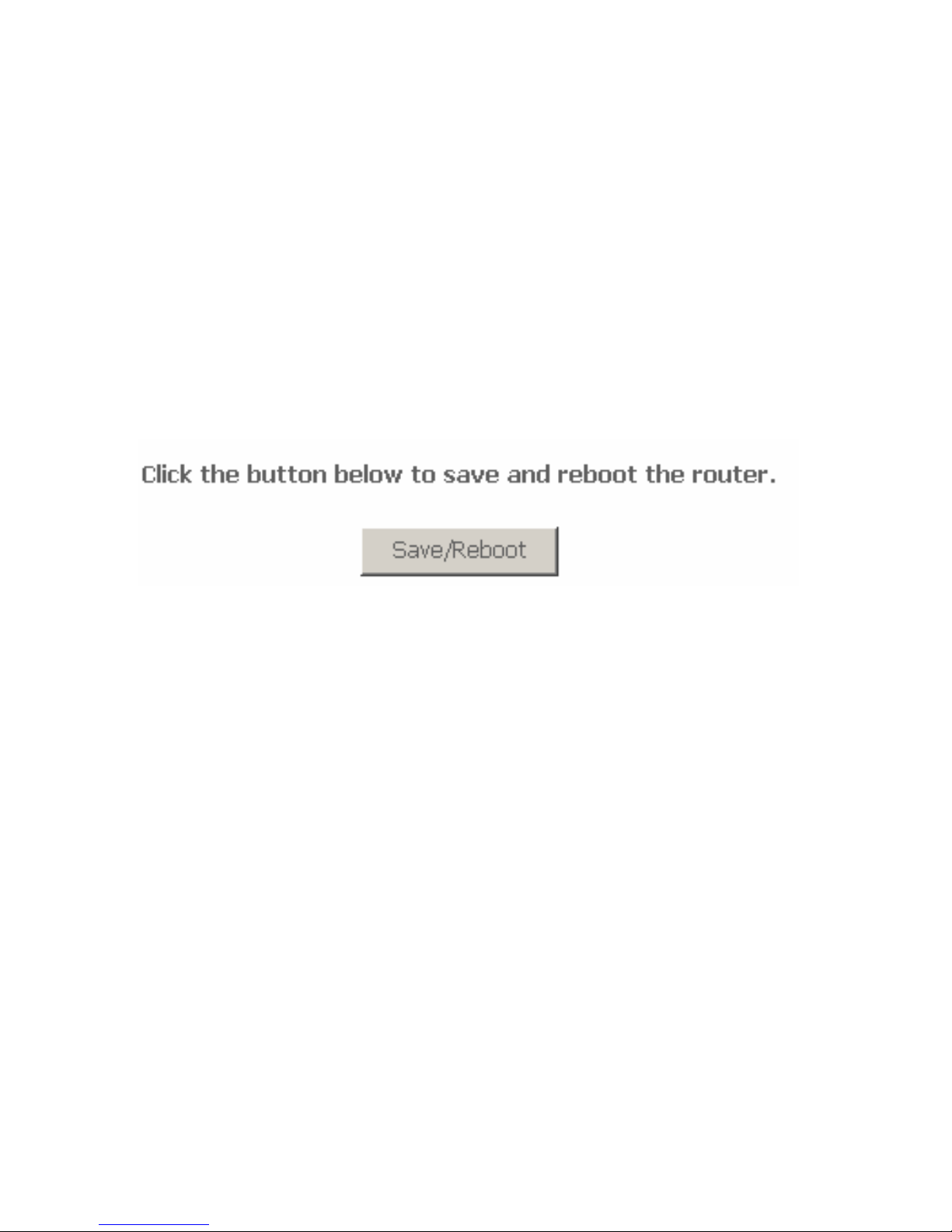
3.6.6 Save/Reboot
Choose Management > Save/Reboot and the following page appears.
In this page, click the Save/Reboot button, and then the router reboots.
4 Q&A
(1) Q: Why all the indicators are off?
A: Check the following:
The connection between the power adaptor and the power socket.
The status of the power switch.
(2) Q: Why the Ethernet indicator is off?
A: Check the following
The connection between the ADSL router and your computer, hub,
or switch.
The running status of your PC, hub, or switch.
(3) Q: Why the Link indicator is off?
A: Check the connection between the “Line” port of router and the wall jack.
(4) Q: Why Internet access fails while the Link indicator is on?
Page 68

66
A: Check whether the VPI, VCI, user name, and password are correctly
entered.
(5) Q: Why does the web configuration page of the router fail to be accessed?
A: Choose Start > Run from the desktop, and ping 192.168.1.1 (IP address
of the router). If the router cannot be reached, check the type of the
network cable, the connection between the router and the PC, and the
TCP/IP configuration of the PC.
(6) Q: How to load the default settings after incorrect configuration?
A: To restore the factory default, keep the device powered on; push a
needle into the hole for about 3 seconds, and then release. The default
IP address and subnet mask of the router are 192.168.1.1 and
255.255.255.0 respectively.
User/password of super user: admin/admin.
User/password of common user: user/user
 Loading...