

Espar Hydronic 4, Hydronic D4 SC, Hydronic 5, Hydronic B5 SC, Hydronic D5 SC Installation, Troubleshooting, Parts Manual
...
Hydronic 4/5 (Coolant Heaters)
Installation • Troubleshooting • Parts Manual
Heater Model 12 V
Hydronic D4 SC 25 1917 01
25 2096 05
Hydronic B4 SC 20 1789 05
Hydronic D5 SC 25 1920 05
25 2098 05
Hydronic D5 S 25 2031 05
25 2100 05
Hydronic B5 SC 20 1791 05
Hydronic B5 S 20 1793 05
Heater Model 24 V
Hydronic D5 SC 25 2147 05
Hydronic D5 S 25 2009 05
Espar
P/N 610-121-0201
January 2001

Table of Contents Page
Introduction Heater Warnings ........................................................ 3
Introduction ........................................................ 4
Specifications ........................................................ 4
Heater Components
Hydronic 4/5 SC, 12 volt, Diesel ........................................................ 5
Hydronic 5 SC, 24 volt, Diesel ........................................................ 6
Hydronic 4/5 SC, 12 volt, Gasoline ........................................................ 6
Hydronic 5 S, 12 + 24 volt, Diesel + Gas ........................................................ 7
Principal Dimensions ........................................................ 8
Installation Heater Location ........................................................ 8
Procedures Heater Mounting ........................................................ 9
Heater Plumbing ........................................................ 10
Fuel System ........................................................ 11
Electrical Connections ........................................................ 13
Exhaust/Intake Connections ........................................................ 14
Operating Switches ........................................................ 15
Heater Operation Pre-Start Procedures ........................................................ 16
Start-Up ........................................................ 16
Running ........................................................ 16
Switching Off ........................................................ 17
Safety Equipment ........................................................ 17
Operational Flow Chart ........................................................ 18
Schematics
Hydronic D4 SC 12 volt, diesel - 25 1917 01 ........................................................ 19
Hydronic D4 SC 12 volt, diesel - 25 2096 05 ........................................................ 20
Hydronic D5 SC 12 volt, diesel - 25 1920 05 ........................................................ 21
Hydronic D5 SC 12 volt, diesel - 25 2098 05 ........................................................ 22
Hydronic D5 SC 24 volt, diesel - 22 2147 05 ........................................................ 23
Hydronic B4 SC 12 volt, gas - 20 1789 05 ........................................................ 23
Hydronic B5 SC 12 volt, gas - 20 1791 05 ........................................................ 23
Hydronic D5 S 12 volt, diesel - 25 2031 05 ........................................................ 24
Hydronic D5 S 12 volt, diesel - 25 2100 05 ........................................................ 24
Hydronic B5 S 12 volt, diesel - 20 1793 05 ........................................................ 24
Hydronic D5 S 24 volt, diesel - 25 2009 05 ........................................................ 24
Maintenance, Periodic Maintenance ........................................................ 25
Troubleshooting & Basic Troubleshooting ........................................................ 25
Repairs Self Diagnostic Troubleshooting ....................................................... 25
Troubleshooting Chart ....................................................... 26
Fuel Quantity Test ........................................................ 29
Heater Disassembly / Repair Steps ........................................................ 30
Heater Components Parts Diagram / Scope ........................................................ 32
Description & Part #’s ........................................................ 33
Parts & Accessories Diagram / Scope ....................................................... 35
Description & Part #’s ....................................................... 36
Special Notes
Note: Highlight areas requiring special attention or clarification.
Caution: Indicates that personal injury or damage to equipment may occur unless specific guidelines are followed.
Warning: Indicates that serious or fatal injury may result if specific guidelines are not followed.

Heater Warnings
Warning To Installer
3
• Correct installation of this heater is necessary to ensure
safe and proper operation.
Read and understand this manual before attempting to
install the heater. Failure to follow all these instructions
could cause serious or fatal injury
Warning - Explosion Hazard
• Heater must be turned off while re-fueling.
• Do not install heater in enclosed areas where combustible fumes may be present.
• Do not install heaters in engine compartments of gasoline powered boats.
Warning - Fire Hazard
• Install the exhaust system so it will maintain a minimum
distance of 50mm (2”) from any flammable or heat sensitive material.
• Ensure that the fuel system is intact and there are no leaks.
Warning - Asphyxiation Hazard
Caution: During electrical welding work on the vehicle
disconnect the power to the heater in order
to protect the control unit.
Note: All measurements contained in this manual
contain metric and approximate SAE equivalents in brackets eg 25mm (1”)
Direct questions to Espar Heater Systems
USA 1-800-387-4800
CANADA 1-800-668-5676
• Route the heater exhaust so that exhaust fumes cannot
enter any passenger compartments.
• If running exhaust components through an enclosed
compartment, ensure that it is vented to the outside.
Warning - Safety Hazard on Coolant Heaters
Used With Improper Antifreeze Mixtures
• The use of Espar coolant heaters requires that the
coolant in the system to be heated contain a proper mixture of water and antifreeze to prevent coolant from
freezing or slushing.
• If the coolant becomes slushy or frozen, the heater’s
coolant pump cannot move the coolant causing a blockage of the circulating system. Once this occurs, pressure
will build up rapidly in the heater and the coolant hose
will either burst or blow off at the connection point to the
heater.
• This situation could cause engine damage and/or personal injury. Extreme care should be taken to ensure a
proper mixture of water and antifreeze is used in the
coolant system.
• Refer to the engine manufacturer’s or coolant manufacturer’s recommendations for your specific requirements.
This publication was correct at the time of print.
However, Espar has a policy of continuous improvement and reserves the right to amend any specifications without prior notice.

4
Introduction
Espar’s Hydronic D4/D5 Heater
Quality engineered to provide a dependable means of heating, the Espar Hydronic 4/5 is a diesel fired coolant heater
capable of between
Hydronic 4 - 1.6 kW to 4 kW/hr (5,500 to 13,700 BTU/hr).
Hydronic 5 - 2.4 kW to 5 kW/hr (8,200 to 17,100 BTU/hr).
This compact coolant heater offers an affordable heating
solution to many applications. The Hydronic 4/5 is ideal for
pre-heating the engines of trucks, cars, off-road equipment,
small trucks and boats. It features automatic heat regulation
while being fuel and power efficient. Since the heater runs on
fuel and 12 or 24 volt power, it is able to perform this completely independently of the vehicle engine. The unit regulates the coolant temperature between a low of 65°C (149°F)
and a high of 80°C (176°F) by automatically cycling the
heater.
The Hydronic 4/5 can be operated from the vehicle cab by an
on/off switch, a preselect timer or a combination of both.
A Flame sensor, temperature regulating sensor and overheat
sensor are among the safety features which makes the
Hydronic D4/D5 a safe and dependable heating system.
Specifications Hydronic 4 Hydronic 5
Heat output (±10%) 4 kW (13,700 BTU/hr) - Boost
3.3 kW (11,300 BTU/hr - High 5 kW (17,000 BTU/hr) - High
1.6 kW (5,500 BTU/hr - Low 2.4 kW (8,200 BTU/hr) - Low
12 volt 24 volt
Current draw (±10%) 4.3 amps Boost
3.0 amps High 4.16 amps High 2.08 amps High
2.0 amps Low 1.91 amps Low 0.95 amps Low
Fuel consumption (±10%) 0.51 l/hr (0.13 US gal/hr) Boost
0.40 l/hr (0.11 US gal/hr) High 0.62 l/hr (0.16 US gal/hr) High
0.20 l/hr (0.05 US gal/hr) Low 0.27 l/hr (0.08 US gal/hr) Low
Operating Voltage Range
Minimum Voltage 10 V 10 V 20.4 V
Maximum Voltage 16 V 16 V 32.0 V
Working pressure 2.5 bar (36 psi) 2.5 bar (36 psi)
Ambient operating temperature -40°C to +80°C (-40°F to 176°F) -40°C to +80°C (-40°F to 176°F)
Overheat temperature shutdown (±5%) 105°C (221°F) 105°C (221°F)
Weight 2.5 kg. (5.5 lbs.) 2.9kg. (6.4lbs)
Controls available On/Off switch or 7-day timer On/Off switch or 7-day timer
Note: The heater is equipped with a high-voltage
cutout as well a low-voltage cutout.

5
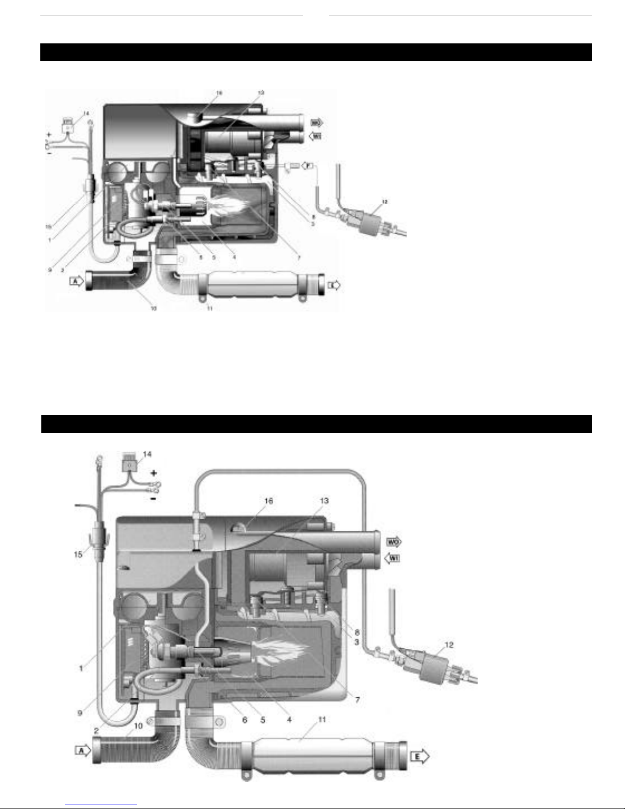
Heater Components - Hydronic 4 & 5 SC versions - 12 Volt - Diesel
25 1917 01
25 2096 05
25 1920 05
25 2098 05
17
1 Combustion air blower wheel
2 Electric motor
3 Heat exchanger
4 Combustion chamber
5 Glow pin
6 Flame sensor
7 Temperature sensor
8 Overheat temperature sensor
9 Control unit
18
A = Combustion air
E = Exhaust
F = Fuel supply line
WO = Water Outlet
WI = Water Inlet
10 Combustion air tube
11 Exhaust tube
12 Fuel-metering pump
13 Coolant pump
14 Main fuse
15 Interface/8-pin connector
16 Bleed screw
17 Push/Pull switch
18 7-day timer
6
Heater Components - Hydronic 5 SC - 24 volt version - Diesel
Heater Components - Hydronic 4 & 5 SC - 12 volt version - Gasoline
25 2147 05
20 1789 05
20 1791 05
7
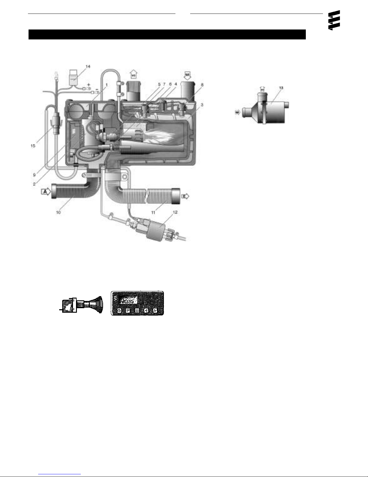
Heater Components - Hydronic 5 S - 12 & 24 volt versions - Diesel & Gasoline versions
25 2031 05
25 2100 05
20 1793 05
25 2009 05
17
18
1 Combustion air blower wheel
2 Electric motor
3 Heat exchanger
4 Combustion chamber
5 Glow pin
6 Flame sensor
7 Temperature sensor
8 Overheat temperature sensor
9 Control unit
A = Combustion air
E = Exhaust
F = Fuel supply line
WO = Water Outlet
WI = Water Inlet
10 Combustion air tube
11 Exhaust tube
12 Fuel-metering pump
13 Coolant pump
14 Main fuse
15 Interface/8-pin connector
16 Bleed screw
17 Push/Pull switch
18 7-day timer
8
Heater Location
Mount the heater in a protected area if you’re in extreme
conditions where heavy salting is experienced.
Eg: storage compartment, engine compartments, step box or
battery box.
Espar recommends you use the boxed unit. Boxed heaters
can be mounted by utilizing one of the existing brackets. See
following page.
If mounting on frame rail use an optional Espar Inside frame
bracket to mount to inside of frame rails. Heaters can also be
mounted on a cross tray behind the cab and on top of
the frame rails.
When mounting the heater adhere to the
following conditions.
• Situate the heater below the normal coolant level of the engine.
• Guard against excessive road spray.
• Keep coolant hoses, fuel lines and electrical wiring as
short as possible
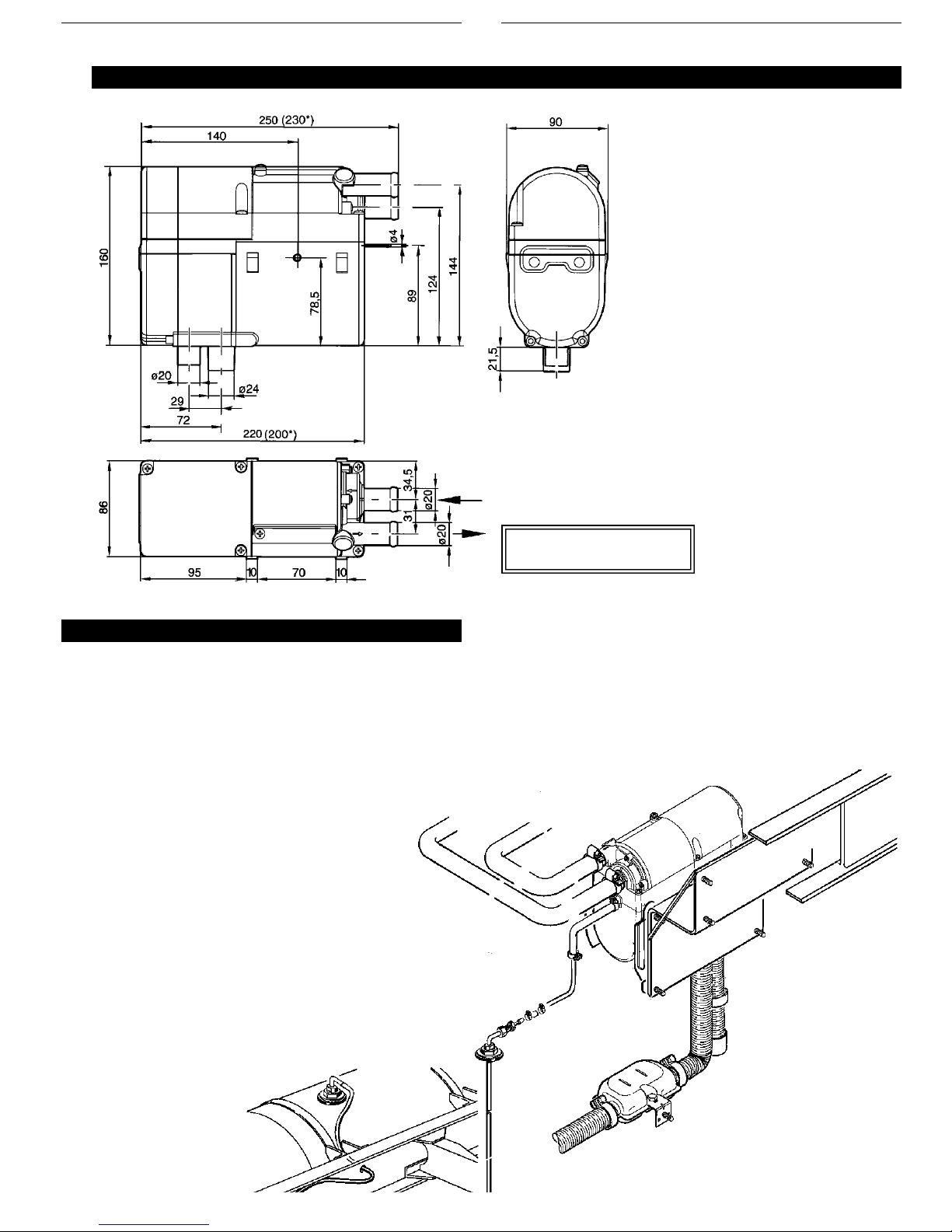
Principal Dimensions - Hydronic D4/D5 SC (values in brackets* = D4SC)
* All measurements in millimeters
25.4mm = 1”
Caution: Guard the heater against excessive road
spray to avoid internal corrosion
For Illustration purposes only
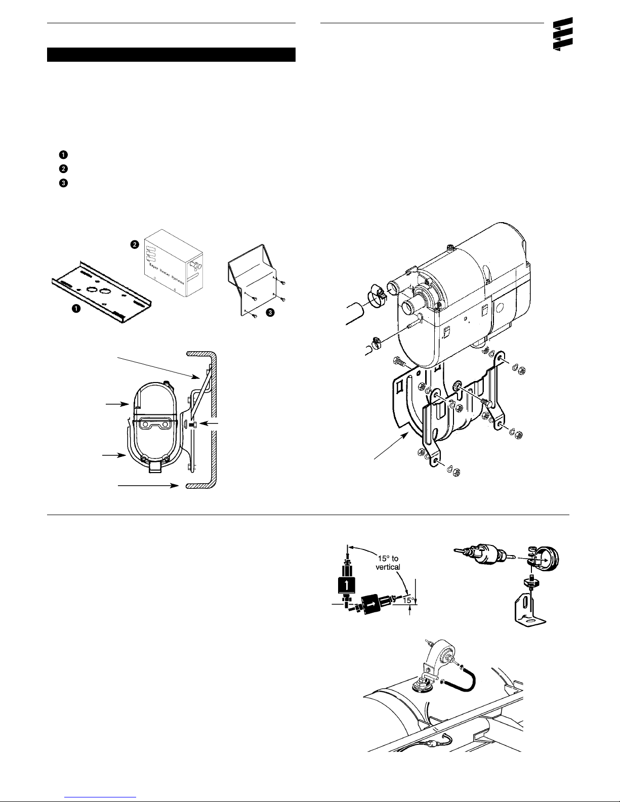
Heater Mounting
9
Mount heater in saddle bracket and secure with hardware
provided. If heater is not a boxed unit, mount bracket onto
inside frame rail bracket. Boxed unit can also be secured to
the inside frame bracket or mounted to the Cross frame
Mounting Tray
Cross Frame Mounting Tray
Hydronic 4/5 box
Inside frame mounting bracket
Inside frame
mounting bracket
Hydronic D4 SC boxed unit P/N CA 2096 55
Hydronic D5 SC boxed unit P/N CA 2098 55
Hydronic
Water Heater
Spacer and screw
Saddle bracket
Inside frame rail
For “S” and gasoline version heaters which have external
fuel metering pumps
• Choose a protected mounting location close to the fuel
pick-up pipe and heater.
• Using the bracket and rubber mount provided, install fuel
pump as shown
Note: Proper mounting angle of the fuel pump is nec-
essary to allow any air or vapor in the fuel lines
to pass through the pump rather than cause a
blockage.
Saddle bracket
10
Heater Plumbing
The heater is incorporated into the engine’s cooling system
for engine preheating
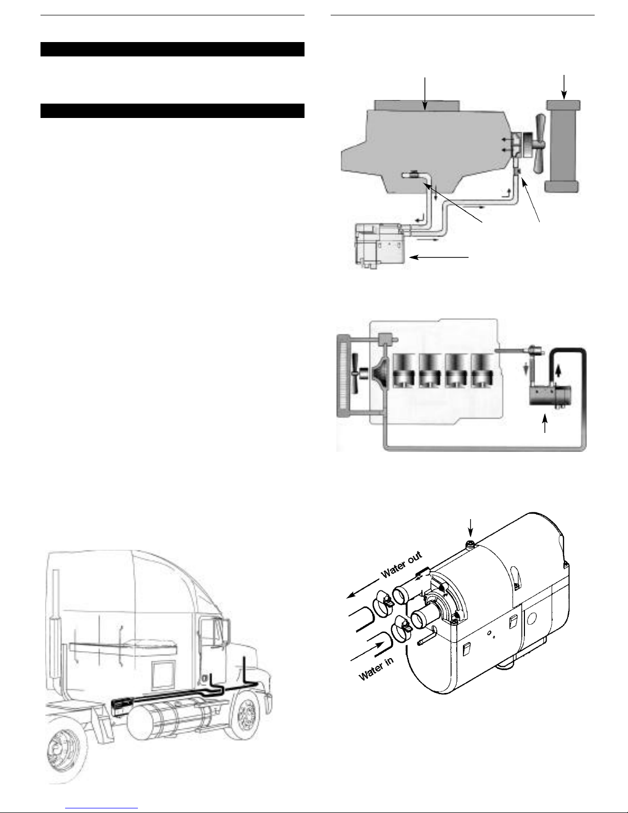
Engine Plumbing
Follow these guidelines and refer to engine plumbing diagram shown below.
• Use existing holes in the engine block (ie. remove
blanking plugs when possible). Install fittings into the block
for pick-up and returns.
• If possible, use shut off valves to ensure the system can
be isolated from the engine when not in use.
• Provide 20mm (3/4”) hose barbs for hose connections.
• Use 20mm (3/4”) hoses to ensure adequate coolant flow.
• Keep the pick up and return points as far apart as
possible to ensure good heat distribution.
• Take the coolant from a low point on the engine to
reduce aeration in the system.
• Ensure proper direction of coolant flow by taking coolant
from a high pressure point in the engine and returning it to
a low pressure point. (ie. pickup from back of block and
return to the suction side of the engine's water pump).
• Ensure adequate flow rate through the heater by comparing the incoming and outgoing coolant temperatures while
the heater is running. If the rise in temperature exceeds
10°C (18°F), coolant flow must be increased by modifying
the plumbing.
• Ensure the heater and water pump are installed as low as
possible to allow the purging of air. Bleed system via radiator or bleed screw located on heater.
Caution: The coolant must contain a minimum of 10%
antifreeze at all times as a protection against
corrosion. Fresh water will corrode internal
heater parts.
Engine
Radiator
External Water Pump
Shut-off valves
Hydronic SC Heater
Bleed Screw
Hydronic “S” version
11
Fuel System
The Hydronic water heaters typically have the fuel metering
pump mounted inside the unit. This is to reduce installation
time and to protect the pump from corrosion. Some versions
have an external fuel metering pump. Refer to graphics for
connections and specifications.
All parts necessary to do the installation are included in the
kit as shown.
Note: Fuel line limits must not be exceeded.
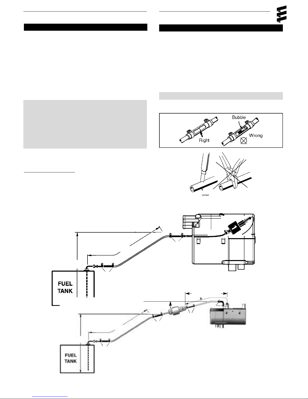
Ensure that the following conditions are met.
Hydronic heater must be within a height of 76cm
(2’6”) from the bottom of the fuel pick-up pipe.
Fuel-metering pump must be within a total
distance of 200 cm (6’6”) from the fuel pick-up pipe.
If the above conditions cannot be met, a heater
with external fuel metering pump must be used.
Fuel System Tolerances
Fuel Line
• Route fuel lines from the fuel pick-up pipe to the heater.
• Use fuel lines provided.
• Other sizes or types of fuel lines may inhibit proper fuel
flow.
• Make proper butt joints using clamps and connector
pieces as shown
• Use a sharp utility knife to cut plastic fuel lines to avoid
burrs.
Note: Butt joints and clamps on all connections.
1. Fuel Pick-Up Pipe
2. Fuel Pipe Reducer
3. 9mm Clamp
4. 3.5mm Rubber Connector
5. 2.0mm White Plastic Fuel Line
6. Fuel Metering Pump
7. 1.5m White Plastic Fuel Line
Max. 76cm (2’6”)
1
Max. 76cm (2’6”)
Max. 2 M (6’6”)
4
2
3
Max. 2 M (6’6”)
2
4
3
5
5
Max. 2 M (6.5’)
4
3
Hydronic Heater
6
4
3
Max. 6 M (19.8’)
4
7
3
6
4
3
1

12
Note: Drill the two (1/4”) holes first.
( Optional Pick-Up Pipe with NPT fitting )
• Remove an existing plug from the top of
the fuel tank.
• Cut the fuel pick-up pipe to length.
• Secure the fuel pick-up pipe into position
using the combined NPT compression
fitting as shown
Double pick ups (used with combo kits)
• Double NPT pipe.
P/N: CA0 12 107
Note: NPT fittings are available in various sizes
(Refer to parts section).
Fuel Pick-Up Pipe
Nut
Sheet Metal Washer
Rubber Gasket
Steel Safety Washer
Holding Tabs
Allow 2.5” from fuel pick-
up to tank bottom. Allow
only 1” for flat bottom
tanks.
End tip of the fuel pick-up
pipe should have angle to
avoid picking up dirt and
subsequent blockage
Fuel Pick-Up Pipe Installation (Standard Pick-Up)
• Choose a protected mounting location close to the pump
and heater. A spare fuel sender gauge plate provides an
ideal mounting location. If one is not available.....
• Drill mounting holes in tank to accommodate pick-up pipe
as shown.
• Cut the fuel pick-up pipe to length. Allow 2-2.5” from bottom of tank.
• Mount the fuel pick-up pipe as shown
• Lower the fuel pick-up pipe (with reinforcing washer) into the
tank using the slot created by the two 0.6cm (1/4”) holes.
• Lift the assembly into position through the 2.5cm (1”) hole.
• Assemble the rubber washer, metal cup washer and nut.
ø 2.5cm (ø1.0”)
ø 0.625 cm (2 Holes)
(ø 1/4”)
1.5 cm
(9/16”)
1.5 cm
(9/16”)
Fuel Pick-Up Pipe reducer

13
Electrical Connections
All parts needed are included with the kit. ( * ) indicates external mounted fuel and or water pump versions of Hydronics.
A. Main Heater Harness...................................................
B. Power Harness............................................................
C. Switch Harness............................................................
D.*Fuel Metering Pump Harness........................................
E.*Water Pump Harness......................................................
Hydronic Heaters
• Connects switch and power harness to the heater harness.
( * in some cases power to fuel metering pump )
• 2 core harness (red, brown).
• Connect red wire to fuse link and terminal.
• Attach ring terminal to vehicle battery (+).
• Connect brown wire to vehicle battery (-) using ring
terminal provided.
• Insert 25 amp fuse
• 4 core harness (red/yellow, brown, yellow, blue/white)
• Run to location of switch. Make terminal connections at
switch. Espar has 2 available switches see switch
instructions on following pages.
• 2 core harness (green, green)
• Connect to fuel metering pump using single terminals
and rubber protective boots (no polarity required).
• 2 core harness (black, brown)
• Connect to main harness at heater.
Caution:
To avoid potential short
circuit damage during
installation, insert 25
amp fuse on power
harness after all
electrical connections
are complete.
E
Note: All harnesses should be cut to length.
All exposed electrical connections should be
coated with protective grease.
Note: Wire must be inserted into fuse holder prior
to terminating
A
D
B
C
7 Day Timer
switch harness
7 Day Timer
 Loading...