

Page 1
D
24 W / D30
W Water Heater
Installation
Troubleshooting &
Parts Manual
Espar
May 1997
For Heater Models
D24W D30W
25 1869 01 00 00 25 1871 01 00 00
25 1870 01 00 00 (NP) 25 1872 01 00 00 (NP)
25 1869 05 00 00 (C) 25 1871 05 00 00 (C)
25 1870 05 00 00 (C) (NP) 25 1872 05 00 00 (C) (NP)
(C) - Compact
(NP)-Nozzle Prepheat
Visit www.butlertechnik.com for more technical information and downloads.
www.butlertechnik.com
Page 2

This publication was cor
rect at the time of going to print. However, Espar Inc. has a
policy of continuous improvement and reserves the right to amend any specifications
without prior notice.
Visit www.butlertechnik.com for more technical information and downloads.
www.butlertechnik.com
Page 3
Table of Contents
I. Introduction 1.
Heater Warnings Page 1-5
2. Introduction
3. Specifications
4. Heater Components
5.
Principal Dimensions
II. Installation Procedures 1. Heater Location Page 5-15
2. Heater Mounting
3. Heater Plumbing
4. Fuel System
5. Electrical Connections
6. Exhaust & Intake Connections
7. Operating Switches
III. Heater Operation 1. Pre-Start Procedures Page 15-19
2. Start-Up
3. Running
4. Switching Off
5. Safety Equipment
6. Operational Flow Chart
7. Wiring Diagrams Model # 25 1869 01/05
25 1871 01/05
25 1870 01/05
25 1872 01/05
IV. Maintenance, 1. Recommended Periodic Maintenance Page 20-31
Troubleshooting & 2. Troubleshooting
Repairs 3. Fuel Quantity Test
4. Adjusting the combustion air
5. Dismantling the water pump
6. Repair Steps
VII. Heater Components 1. Parts Diagram Page 32-39
2. Description & Part #’s
Special Notes
Note: Highlight areas requiring special attention or clarification.
Caution: Indicates that personal injury or damage to equipment may occur unless specific guidelines are
followed.
Warning: Indicates that serious or fatal injury may result if specific guidelines are not followed.
Visit www.butlertechnik.com for more technical information and downloads.
www.butlertechnik.com
Page 4
1
1. Heater Warnings
Warning To Installer
• Correct installation of this heater is necessary to ensure safe and proper operation.
Read and understand this manual before attempting to install the heater. Failure to follow all
these instructions could cause serious or fatal injury
Warning - Explosion Hazard
• Heater must be turned off while re-fueling.
• Do not install heater in enclosed areas where combustible fumes may be present.
• Do not install heaters in engine compartments of gasoline powered boats.
Warning - Fire Hazard
• Install the exhaust system so it will maintain a minimum distance of 2” from
any flammable or heat sensitive material.
• Ensure that the fuel system is intact and there are no leaks.
Warning - Asphyxiation Hazard
• Route the heater exhaust so that exhaust fumes cannot enter any
passenger compartments.
• If running exhaust components through an enclosed compartment, ensure that it is
vented to the outside.
Warning - Safety Hazard on Coolant Heaters Used With Improper Antifreeze Mixtures
• The use of Espar coolant heaters requires that the coolant in the system to be heated
contain a proper mixture of water and antifreeze to prevent coolant from freezing
or slushing.
• If the coolant becomes slushy or frozen, the heater’s coolant pump cannot move the
coolant causing a blockage of the circulating system. Once this occurs, pressure willbuild
up rapidly in the heater and the coolant hose will either burst or blow off at the connection
point to the heater
.
• This situation could cause engine damage and/or personal injury. Extreme care should
be taken to ensure a proper mixture of water and antifreeze is used in the coolant system.
• Refer to the engine manufacturer’s or coolant manufacturer’s recommendations
for your specific requirements.
Note: During electrical welding work on the vehicle disconnect the power to the heater in order to protect
the control unit.
Direct questions to Espar Heater Systems USA 1-800-387-4800
CDA 1-800-668-5676
Visit www.butlertechnik.com for more technical information and downloads.
www.butlertechnik.com
Page 5
2
2. Introduction
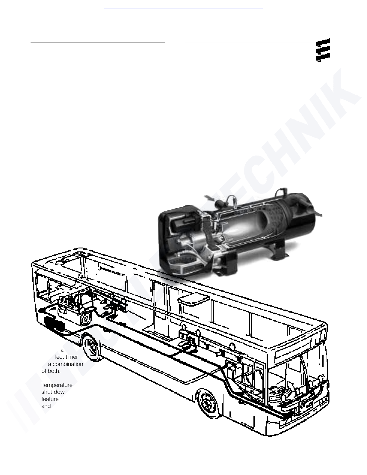
Espar’s D24W / D30W Coolant Heater
Quality engineered to provide a dependable means
of heating, the Espar D24W and D30W are diesel
fired coolant heaters capable of putting out between
82,000 to 102,000 BTU’s/hr
.
The heater pumps coolant from the engine, heats it
and returns it to the engine. By routing the hot
coolant through heat exchangers it is also possible
to heat the interior of the vehicle. It is also possible
to route the coolant through stainless steel tubing to
pre-heat hydraulic fluid and fuel in off-road applications.
Since the heater runs on diesel fuel and 24 volt
power, it is able to perform this completely independently of the vehicle engine. A temperature regulating switch in the unit regulates the coolant temperature between a low of 149°F (65°C)
and a high of 176°F (80°C) by automatically
cycling the heater.
The D24W /D30W can be operated from
the vehicle cab by
an on/off
switch, a
preselect timer
or a combination
of both.
T
emperature regulating and overheat
shut down switches are among the safety
features which make the D24W / D30W a safe
and dependable heating system.
Visit www.butlertechnik.com for more technical information and downloads.
www.butlertechnik.com
Page 6
3
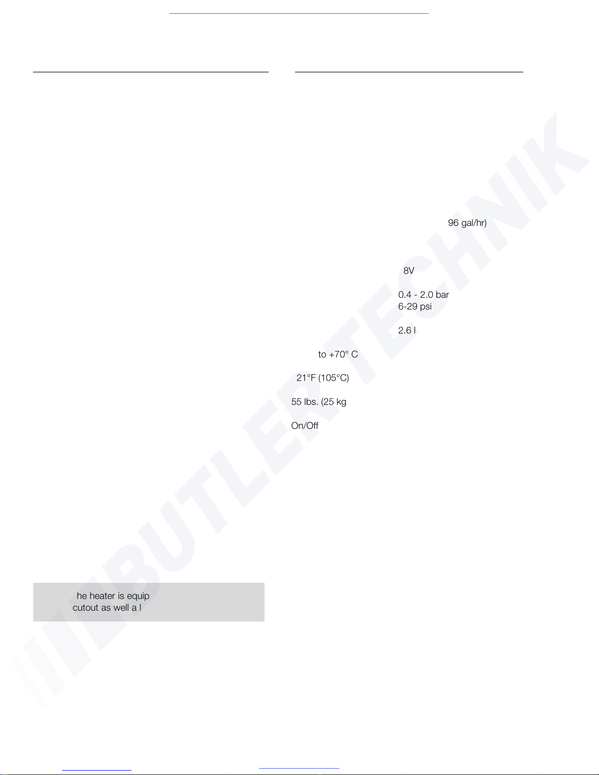
3. Specifications - heater
Model (24V) D24W D30W
Heat output (±10%) 82,000 BTU (24Kw) 102,000 BTU (30Kw)
Current draw (±10%) 5 amps 5.5 amps
(without water pump)
Fuel consumption (±10%) 2.90 l/hr (0.76 gal/hr) 3.65 l/hr (0.96 gal/hr)
Operating Voltage Range
Minimum Voltage 20V 20V
Maximum Voltage 28V 28V
W
orking pressure 0.4 - 2.0 bar 0.4 - 2.0 bar
6-29 psi 6-29 psi
Water capacity 2.6 l 2.6 l
Ambient temperature (minimum) -40°C to +70° C -40°C to +70° C
Overheat temperature Shutdown (±5%) 221°F (105°C)
Weight 55 lbs. (25 kg.)
Controls available On/Off switch, 99hr. timer or 7 day timer.
Specifications - water pump Standard High capacity
Voltage 24 V ± 20% 24 V ± 20%
Current draw 4.6 amps 10.4 amps
Water throughput 5000 l/hr - 200mbar 6000 l/hr - 200mbar
Note: The heater is equipped with a high voltage
cutout as well a low voltage cutout.
Visit www.butlertechnik.com for more technical information and downloads.
www.butlertechnik.com
Page 7
4
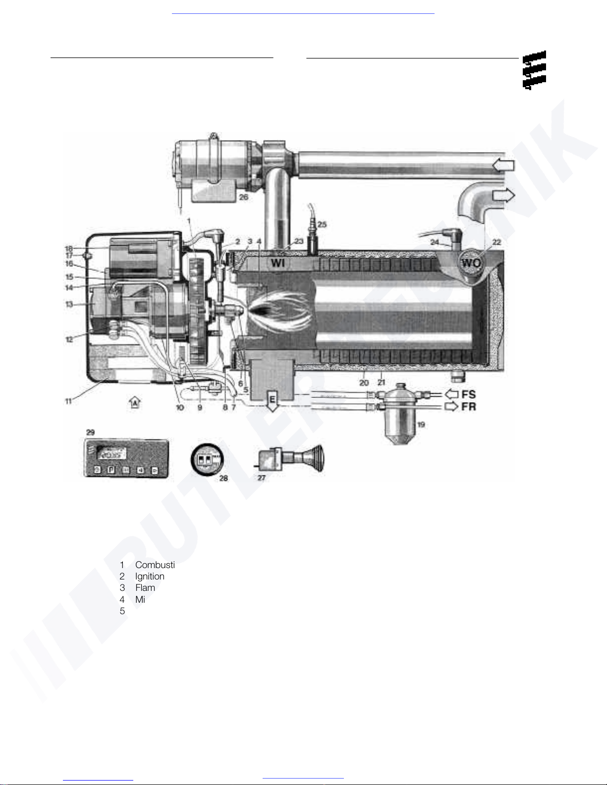
4. Heater Components
1 Combustion air blower wheel
2
Ignition electrode
3 Flame monitor
4 Mixing head
5
Fuel nozzle
6 Fuel nozzle pre heating (optional)
7 Fuel line
8 Air baffle plate
9 Combustion air control plate
10 Electric motor
11 Silencer
12 Fuel connection
13 Fuel pump
14 Fuel compression line
15 Control unit
16 Fuel solenoid valve
17 Diagnostics Display
18 Ignition spark generator
19 Fuel filter
20 Heat exchanger with flame pipe
21 Outer casing
22 Water connection socket - outlet
23 Water connection socket - inlet
24 Safety thermal cut-out switch
25 Temperature Probe
26 Water pump
27 Push/Pull switch
28 99 hr timer
29 7 day timer
A = Combustion air
E = Exhaust
F = Fuel supply line
FR = Fuel return line
WO = Water Outlet
WI = Water Inlet
Visit www.butlertechnik.com for more technical information and downloads.
www.butlertechnik.com
Page 8
II. Installation Procedures
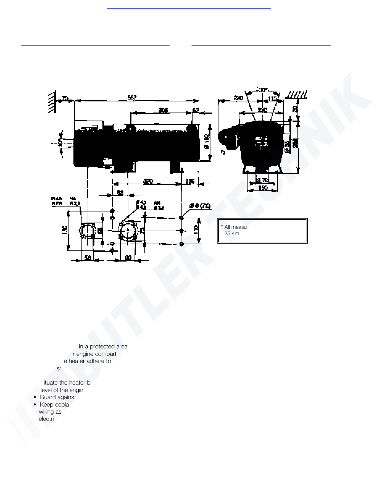
1. Heater Location
Mount the heater in a protected area eg: storage
compartment or engine compartments. When
mounting the heater adhere to the following
conditions:
• Situate the heater below the normal coolant
level of the engine.
• Guard against excessive road spray.
• Keep coolant hoses, fuel lines and electrical
wiring as short as possible (see fuel line &
electrical wiring specs on pgs.9-11)
5
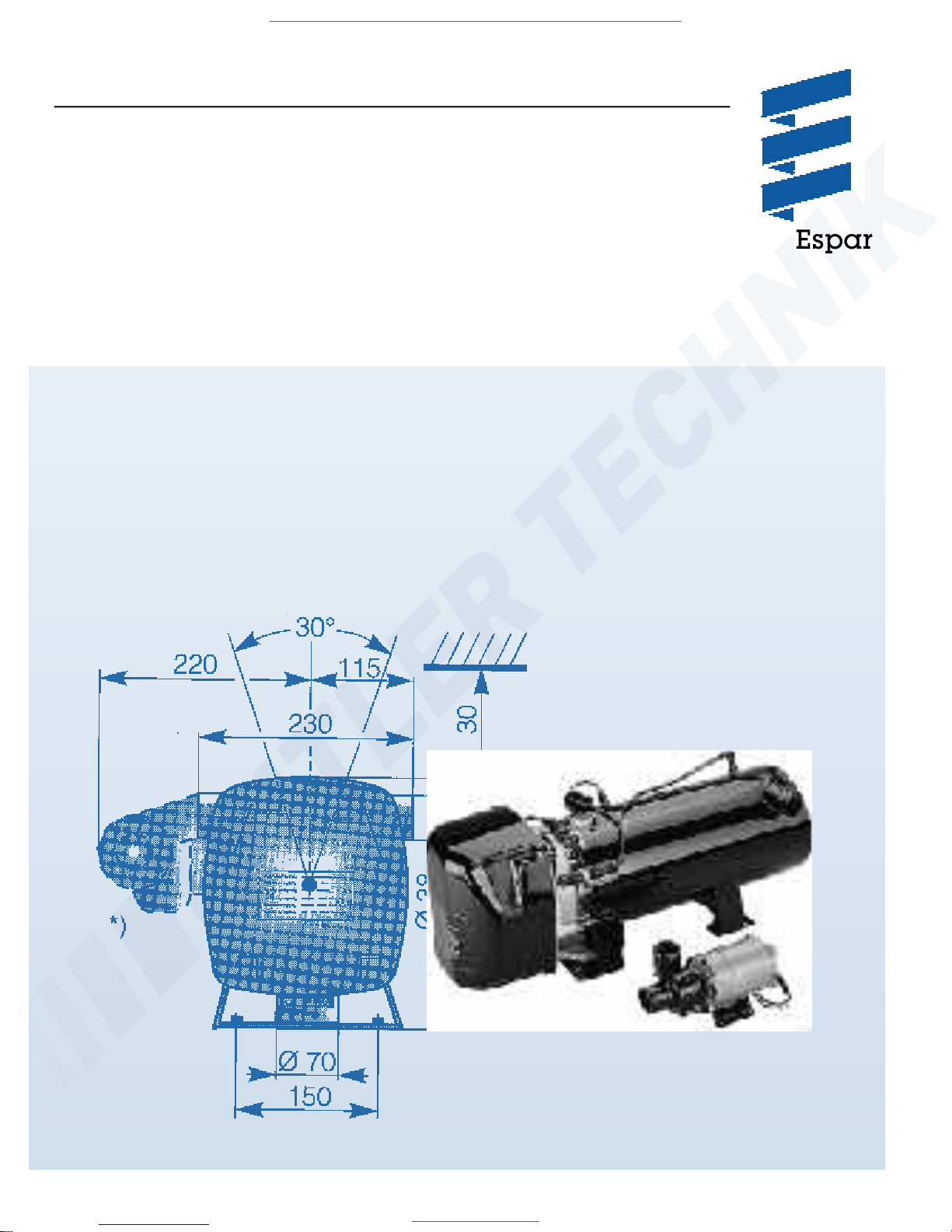
5. Principal Dimensions
* All measurements in millimeters
25.4mm = 1”
2. Heater Mounting
Using the hole pattern shown above to mount
the heater using the following mounting methods:
• Fabricate support brackets.
• Use an existing compartment floor ( if available).
Visit www.butlertechnik.com for more technical information and downloads.
www.butlertechnik.com
Page 9
6
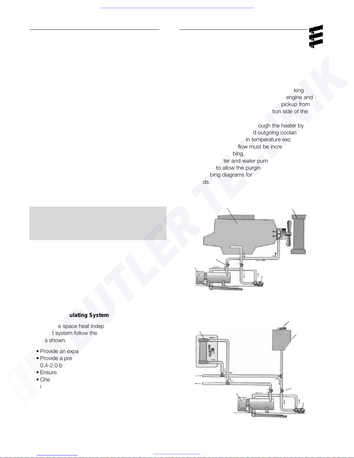
3. Heater Plumbing
The heater can either be incorporated into the
engines cooling system for engine preheating or can
be provided with its own circulation system for space
heating (ie. marine)
Engine Plumbing
To pre heat engines, follow these guidelines and
refer to engine plumbing diagram shown below.
• Install fittings into the block for pick up and
returns.
• Use existing holes in the engine block (ie.
remove blanking plugs when possible).
• Use shut off valves to ensure the system can be
isolated from the engine when not in use.
• Provide 1.5" (37.5mm) hose barbs for hose
connections.
• Use 1.5” (37.5mm) hoses to ensure adequate
coolant flow
.
D24W / D30W plumbed for engine pre-heat
Isolated Circulating System
To provide space heat independent from the engines
coolant system follow these guidelines and illustrations shown.
• Provide an expansion tank
• Provide a pressure relief valve.
0.4-2.0 bars (6-29 psi)
•
Ensure proper direction of coolant flow.
• Check flow rate through heater by comparing the
incoming and out going coolant temperatures. If the
rise in temperature exceeds 18°F (10°C), coolant
flow must be increased by modifying plumbing .
• The heater and water pump should be installed as
low as possible to allow for the purging of air.
• Use a minimum of 1.5” (37.5mm) hose to and from
the heater.
• Keep the pick up and return points as far apart
as possible to ensure good heat distribution.
• Take the coolant from a low point on the engine
to reduce aeration in the system.
• Ensure proper direction of coolant flow by taking
coolant from a high pressure point in the engine and
returning it to a low pressure point. (ie. pickup from
back of block and return to the suction side of the
engine's water pump).
• Ensure adequate flow rate through the heater by
comparing the incoming and outgoing coolant
temperatures. If the rise in temperature exceeds
18°F (10°C), coolant flow must be increased by
modifying the plumbing.
• Ensure the heater and water pump are installed as low
as possible to allow the purging or air.
• See plumbing diagrams for alternative plumbing
methods.
1
2
3
4
5
1 Heater
2
Water pump
3 Shut-off valve
4
Engine
5 Radiator
6 Heat Exchanger
7 Expansion Tank
8 Safety valve
Note: The coolant must contain a minimum of
10% antifreeze at all times as a protection
against corrosion. Fresh water will corrode
internal heater parts.
D24W / D30W plumbed in isolated circuit
8
6
1
3
2
7
Visit www.butlertechnik.com for more technical information and downloads.
www.butlertechnik.com
Page 10
7
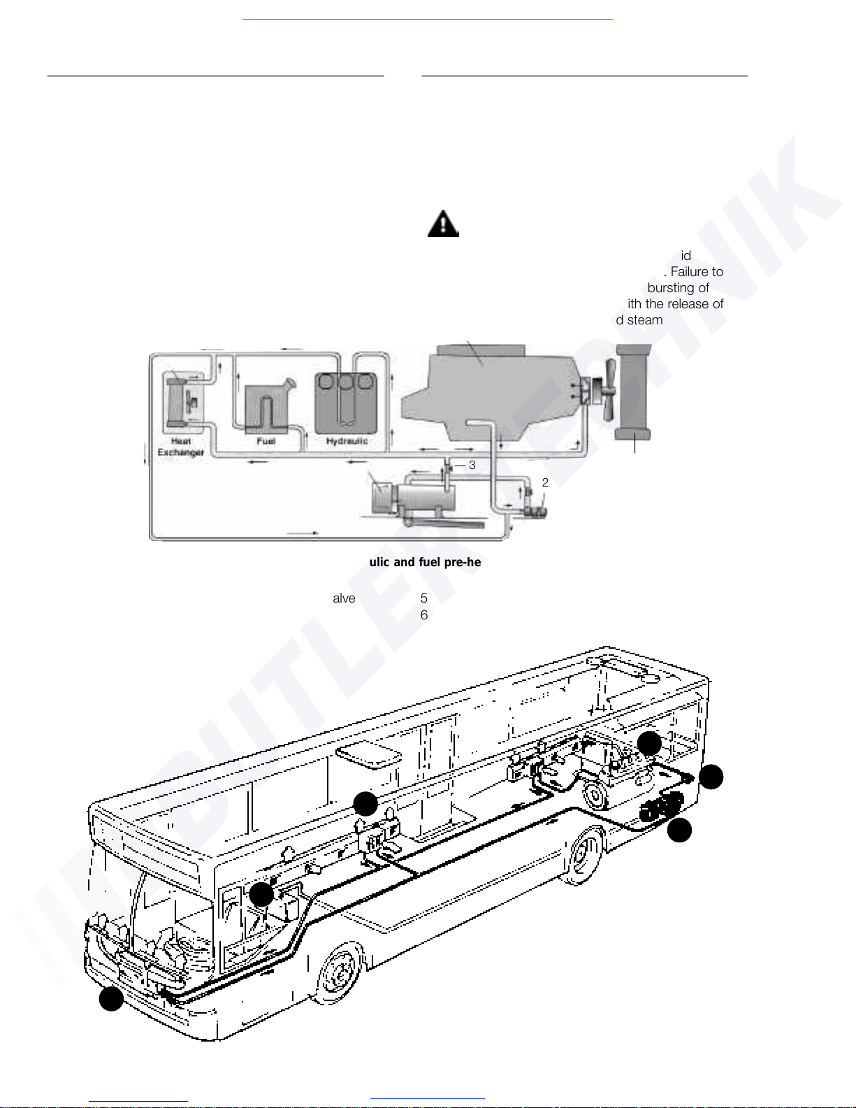
Bus Plumbing Diagram
D24W / D30W plumbed for hydraulic and fuel pre-heat with heat exchanger
1 Heater 3
Shut-off valve 5 Radiator 7
Fuel tank
2 Water pump 4 Engine 6 Hydraulic fluid tank 8 Heat exchanger
4
2
3
1
5
6
7
8
1 Heater 4 Vehicle engine
2 Water pump 5 Front heater
3 Fuel Tank connect 6 Floor Heater
Adding Heat Exchangers, Fuel warmers or
Hydraulic warmers
• Maintain proper flow through heater at all times
• Provide air relief cocks at the heat exchanger.
• If the water piping cannot be run with a continuos
rise to the heat exchangers, provide air relief
cocks at high points.
• Connect plumbing circuits in parallel to avoid
reduction of plumbing hose size and avoid restriction of flow.
• Ensure thermostat and flow control valves do not
completely close off flow through heater
• Refer to plumbing diagrams for examples
Warning: Ensure that a coolant flow path
is open at all times while the
heater is operating to avoid
overheating conditions. Failure to
do so may result in bursting of
coolant hoses with the release of
hot coolant and steam
6
5
1
2
3
4
Visit www.butlertechnik.com for more technical information and downloads.
www.butlertechnik.com
Page 11
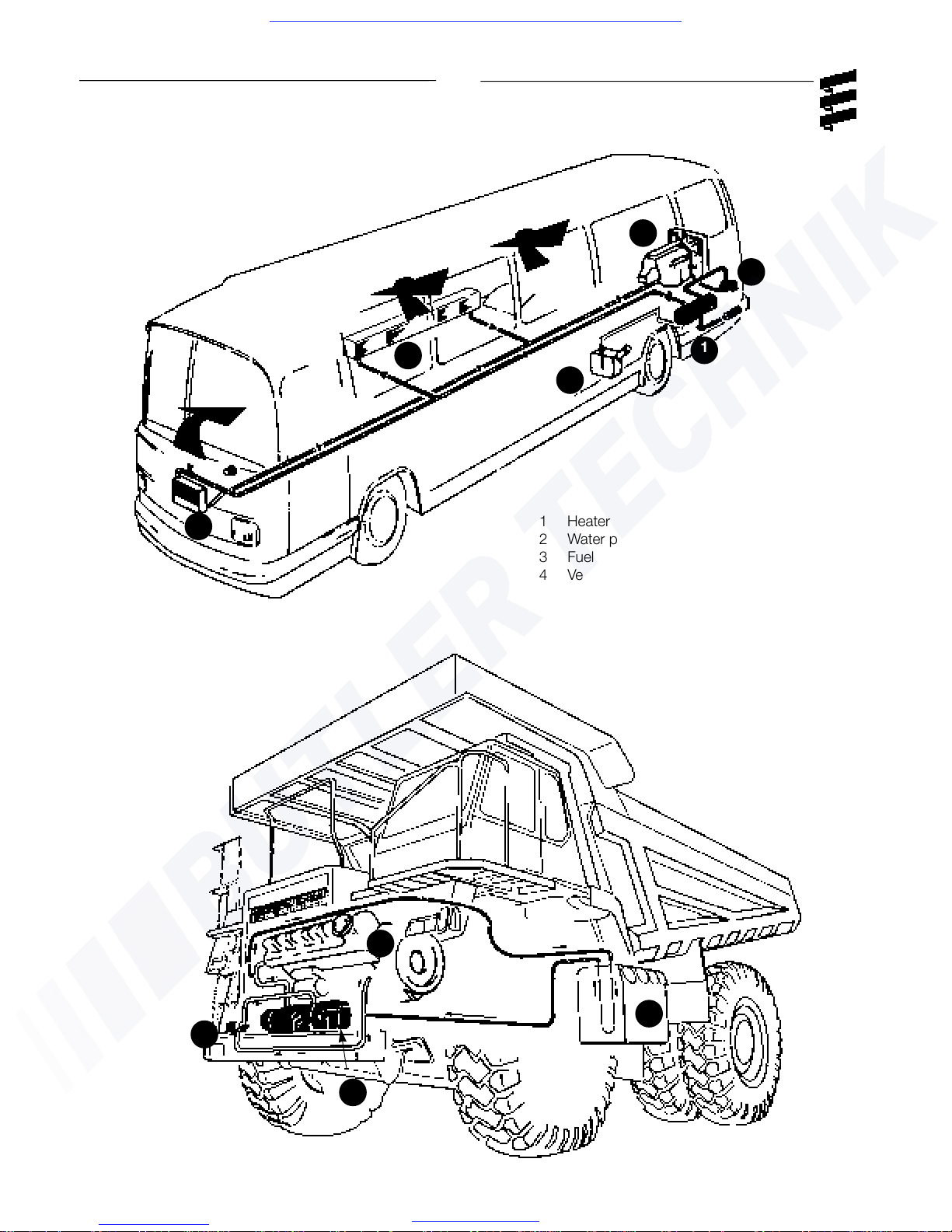
8
Off-road
plumbing
diagram
1 Heater 5
Front heater
2 Water pump
6 Floor Heater
3 Fuel Tank connect 7 Hydraulic Tank
4 Vehicle engine
6
7
5
1
1
2
2
3
4
4
Visit www.butlertechnik.com for more technical information and downloads.
www.butlertechnik.com
Page 12
9
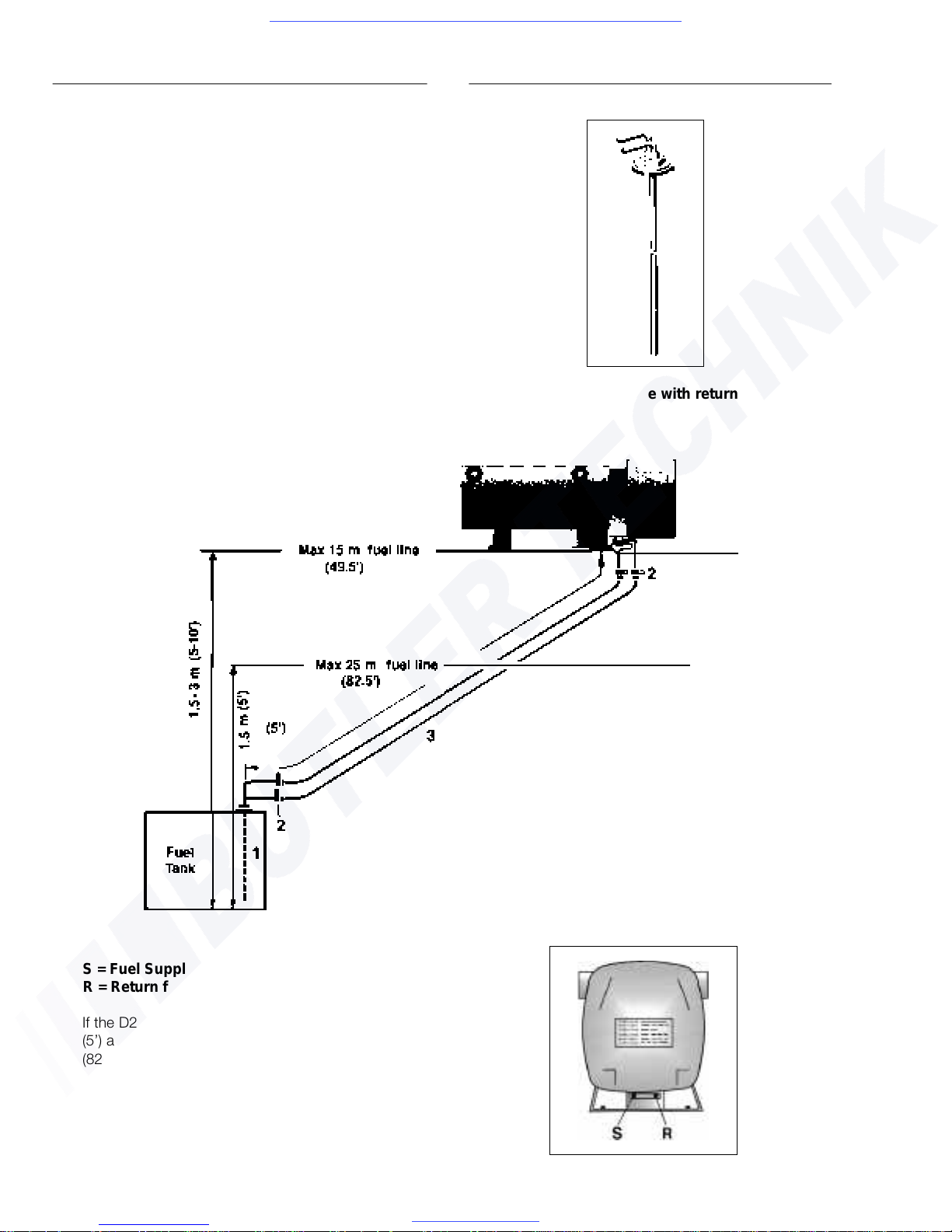
4. Fuel System
To connect the fuel supply to the heater (at the fuel filter), a supply line and a return line to the tank are
necessar
y. To accommodate these lines at the tank, a
fuel pick-up pipe with a return stem is available.
The fuel filter is located into the feed line near the
heater. It is recommended that a shut off valve be fitted near the heater on both the intake and return
lines. (fuel filter and shut off valves are already
attached to the heater in the compact version). Refer
to Figures below for connections and specifications.
Fuel System Tolerances
1. Fuel Pick-Up Pipe
2. 11mm Clamp
3. 5.0mm Fuel line
S = Fuel Supply
R = Return fuel
If the D24W / D30W heater is situated within 1.5 m
(5’) above the fuel tank, a permissible 25 meters
(82.5’) of fuel line can be used.
If it is between 5 -10’ (1.5 - 3 m) above the fuel
tank a maximum fuel line of 15 m (48.5’) is permissible.
Fuel pick up pipe with return
Visit www.butlertechnik.com for more technical information and downloads.
www.butlertechnik.com
Page 13

10
Fuel Pick-Up Pipe Installation (Standard Pick-Up)
Choose a protected mounting location close to the
pump and heater. A spare fuel sender gauge plate
provides an ideal mounting location.
• Drill the mounting holes as shown in Figure 1.
• Cut the fuel pick-up pipe to length.
• Mount the fuel pick-up pipe as shown in
Figure 2.
• Lower the fuel pick-up pipe (with reinforcing
washer) into the tank using the slot created by
the two 1/4” holes.
• Lift the assembly into position through the 1”
hole.
• Assemble the rubber washer, metal cup washer
and nut.
Note: Drill the two 1/4” holes first.
Figure 2
ø 1.0” (2.5cm)
ø 1/4” (2 Holes)
(ø 0.625 cm)
9/16”
(1.5 cm)
9/16”
(1.5 cm)
Fuel Pick-Up Pipe Return
Fuel Pick-Up Pipe Supply
Nut
Sheet Metal Washer
Rubber Gasket
Steel Safety Washer
Holding Tabs
Allow 4” from fuel pick-up to tank bottom.
Allow only 1” for flat bottom tanks.
End tip of the fuel pick-up pipe should have
angle so as to avoid picking up dirt and subsequent blockage.
Figure 1
Visit www.butlertechnik.com for more technical information and downloads.
www.butlertechnik.com
Page 14
Note: All harnesses should be cut to length.
All exposed electrical connections should
be coated with protective grease.
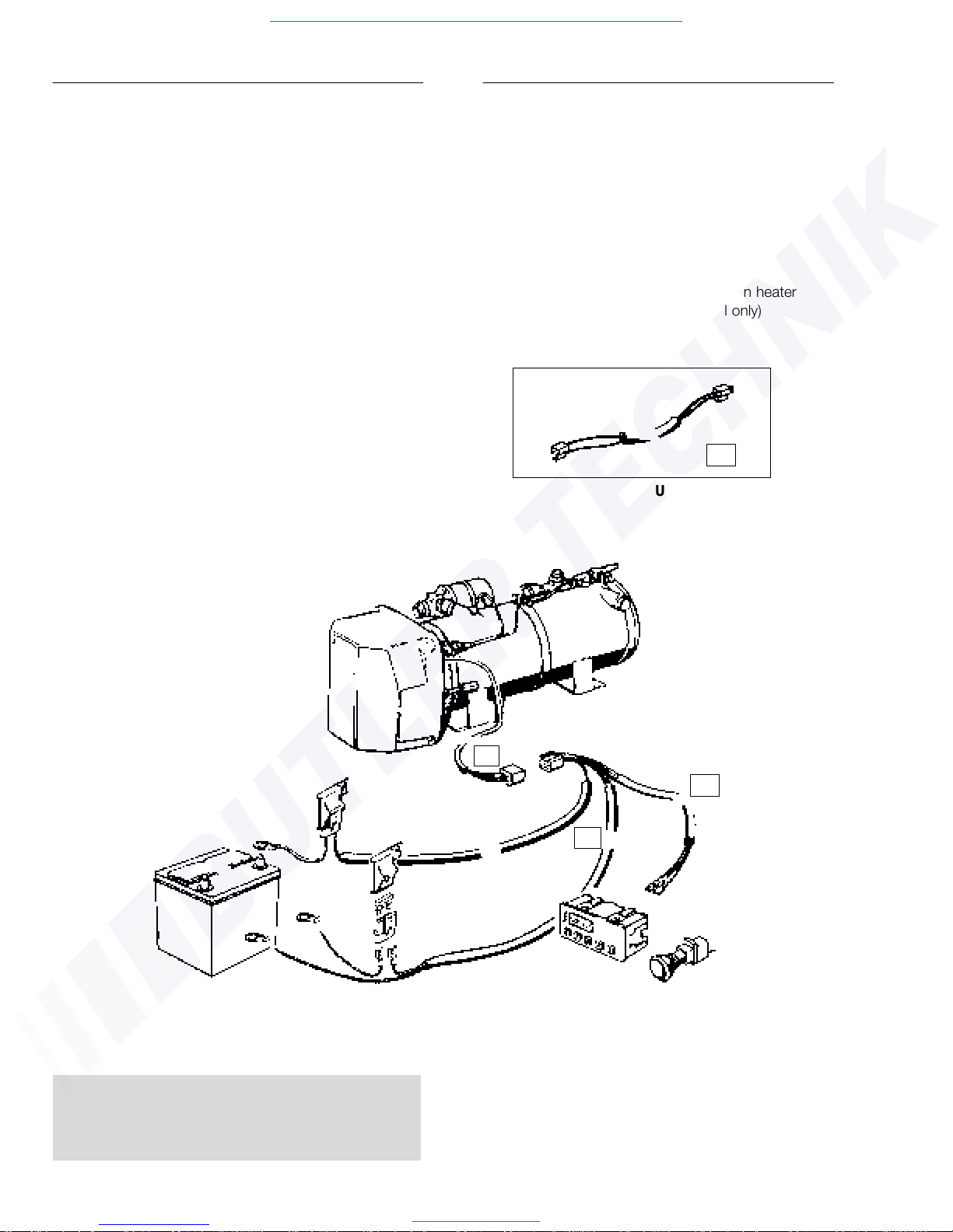
5.
Electrical Connections
Caution: To avoid potential short circuit damage
during installation, make connection to
the positive terminal at battery after all
electrical connections are complete.
A. Power/ • 3 core harness (red, red, brown).
Pump • Connect red wires to vehicle battery (+)
Harness via fuse link provided, using ring
terminal provided.
• Connect brown wire to vehicle battery (-)
using ring terminal provided.
B. Switch • 3 core harness (red, brown, yellow).
Harness • Run to location of switch.
C.
Main • Connects the above harnesses to
Heater control unit and other components
Harness inside the heater cover.
A
B
D
C
11
D.
Pump • 2 core harness(red, brown)
Harness Connects to pump and main heater
Extension harness (Universal model only)
Universal model
Compact version
Visit www.butlertechnik.com for more technical information and downloads.
www.butlertechnik.com
Page 15

12
WARNING: The exhaust is hot, keep a minimum
of 2” clearance from any heat
sensitive material. Route exhaust
so that the exhaust fumes cannot
enter the passenger compartment.
6. Exhaust Connection
A 2.8” (70 mm) flexible tube exhaust pipe with a
length no more than 4m long is required for the
exhaust. A 3” (75mm) muffler clamp is needed to
secure the exhaust to the the heater. Connect the
exhaust as follows:
• Connect the exhaust pipe to the exhaust tube
on the heater and attach with clamp provided.
• Run exhaust to an open area to the rear or side
of the vehicle so that fumes can not build up
and enter the passenger compartment or the
heater combustion air intake.
• Install exhaust pipe with a slight slope or drill a
small hole in the lowest point to allow water to
run off. Any restriction in exhaust will cause
operational problems.
• Secure the exhaust pipe at the heater using clamps
and holders. Secure the exhaust pipe externally
using clamps and holders.
Caution: Run exhaust so that it cannot be plugged
by dirt, water or snow.
Ensure the outlet does not face into the
vehicle slip stream.
Max 13’ (4m)
Exhaust
Intake Connection
The combustion air must be drawn in from the outside.
The combustion air opening must be kept free at all
times. When installing the heater in a closed box care
must be taken to ensure that it is sufficiently ventilated
from the outside. Use a lourved type plate or grill.
Caution: - Do not install the intake opening facing the
vehicle slipstream, ensure that the opening
cannot become clogged with dirt or snow
and that any water entering the intake can
drain away.
Visit www.butlertechnik.com for more technical information and downloads.
www.butlertechnik.com
Page 16

7.
Operating Switches
A Push/Pull switch, optional 99 Hour Digital Timer or a
7 Day Timer are available for the heater. Connect the
operating switch as follows.
Push/Pull Switch
• Mount switch in a location where it is easily
accessible.
•
Mount using hardware supplied.
• Connect the 25’ switch harness to the connector
at the heater and run the harness to the switch
location.
• Cut harness to length at the switch and install
terminals.
• Connect wiring as shown in Figure 3.
13
Figure 3
Note: Wired as above the switch light glows when
pulled out and is off when pushed in.
99 Hour Digital Timer
This timer is pre-set by Espar to operate the
heater for one (1) hour only. If an alternative run
time setting is desired refer to the instructions
provided with the timer
.
• Mount the timer using a 2” hole in the dash or use
the optional mounting bracket.
•
Mount timer using hardware supplied.
• Connect the 25’ switch harness to the connector
at the heater and run the harness to the switch
location.
• Cut harness to length and terminate wires.
•
Attach using connector provided.
Red-Red
Y
ellow-Yellow
Brown-Brown
Control Wiring
Push/Pull Switch
Brown - 31
Red
- K (15)
Yellow - 15 (K)
Visit www.butlertechnik.com for more technical information and downloads.
www.butlertechnik.com
Page 17

7 Day Timer
The 7 day timer is capable of setting up to 3 preset
start times within 24 hrs. or 1 start time with in 7
days. It also has other functions such as a curr
ent
time display and a heater numeric fault code. Refer
to instructions provided with timer for setting options.
• Mount timer and bracket in a suitable location.
• Connect the 25’ switch harness to the connector
at the heater and run the harness to the
switch location.
• Cut harness to length at the switch and install
terminals.
• Connect switch harness to timer....Figure 4
• Refer to timer instructions for other wiring
options.
14
Figure 4
Note: The timer display is automatically illuminated
while the heater is operating. Connecting
the grey wire to the vehicle dimmer switch
will allow the timer display to illuminate with
the vehicles dash lights. An alternative to
connecting the black wire to the vehicle
ignition accessories “On” circuit may also be
considered for some applications where
extended run times are desired. Connecting
the black wire with the red wire will enable
the heater to run continuously whether the
heater is switched on manually or through
the preset function.
Visit www.butlertechnik.com for more technical information and downloads.
www.butlertechnik.com
Page 18

15
III. Heater Operation
1. Pre-Start Procedures
Upon completion of installation prepare the
heater as follows:
• Check all fuel, electrical and plumbing
connections.
•
Refill the engine coolant
• Bleed air from the coolant system by loosening
the locking screw on the coolant inlet barb.
• Re-tighten screw
• Run engine to further bleed the system.
• T
op up engine coolant.
2. Start Up
Once switched on the following sequence occurs:
• Control unit does a systems check ( flame sensor,
temperature, safety thermal cutout fuse and
various other control unit checks).
• Water pump starts circulating coolant fluid.
• Electric motor starts the combustion air
blower and fuel pump.
• A motor system test is performed and the
electric motor is shut off while the control unit
measures the generated voltage.
• Fuel solenoid opens enabling fuel to be sprayed
into the combustion chamber.
• Atomized fuel is then ignited by a high voltage
ignition spark.
• Once ignition takes place a photoresistive cell
automatically switches the ignition system off
(ignition time: 10 seconds maximum).
3. Running
Once ignition is successful the following operations
take place:
• Heater runs in full heat mode and the temperature
is monitored at the heat exchanger.
• If the temperature rises above 80°C(176°F) the
heater automatically switches itself off.
• The water pump continues to circulate coolant to
allow the heater to monitor engine temperature.
• When the temperature drops below 65°C(149°F)
the heater will cycle itself back on automatically.
• The heater continues to run as described above
until it is switched off, either manually, automatically
by a timer or heater malfunction shutdown.
• The set value of the water temperature is adjusted
in the control unit. If a temperature reducer is con
nected the control temperature is reduced by
approx. 8°C. ( see wiring diagram)
Note: If the heater fails to start the first time it will
automatically attempt a second start. If
unsuccessful the heater will shut down
completely.
Note: On initial start up the heater may require
several start attempts to self prime the fuel
system.
Note: During operation the heater continually
senses the input voltage from the batteries,
if the input voltage drops to approximately
20 volts or rises above 30 volts the heater
will automatically shut down.
4.
Switching Off
• When the heater is switched off the fuel solenoid
valve closes, shutting off the fuel supply.
• The flame is extinguished and a switch off lag time
begins. (2 1/2-3min.)
• The combustion air blower and water pump continue
to run for a three minute cool down cycle clearing
residual combustion gases and drawing heat off the
heat exchanger preventing any local overheating.
• After the three minute cool down the heater shuts off.
Visit www.butlertechnik.com for more technical information and downloads.
www.butlertechnik.com
Page 19

16
5. Safety Equipment
The control unit, overheat switch and flame sensor
(photoresistive cell) continually monitor heater functions and will shut down the heater in case of a malfunction.
• The control unit ensures electrical circuits (fuel
pump, combustion air blower etc.) are complete
prior to starting the heater.
• If the heater fails to ignite within 10 seconds of the
fuel solenoid opening, a “no start safety shutdown”
follows.
• If the heater flames out during operation, the
heater automatically attempts to restart. If the
heater fails to ignite within 10 seconds of fuel
deliver
y, or ignites but flames out again within
3 minutes, “flame out” shutdown follows.
• Overheating due to lack of water, a restriction or a
poorly bled coolant system results in the overheat
cutout fuse tripping. Fuel delivery will cease and
an “overheat shut down” follows.
• If at any time the voltage drops below 20V, or
rises above 30V, a “high/low voltage” shutdown
follows (after a 20 second delay).
Visit www.butlertechnik.com for more technical information and downloads.
www.butlertechnik.com
Page 20

17
6. Operational Flow Chart
Visit www.butlertechnik.com for more technical information and downloads.
www.butlertechnik.com
Page 21

18
Wiring Diagram (no nozzle pre-heat)
D24W D30W
model #’s model #’
s
25 1869 01 00 00 25 1871 01 00 00
25 1869 05 00 00 (c) 25 1871 05 00 00 (c) (c) compact
Visit www.butlertechnik.com for more technical information and downloads.
www.butlertechnik.com
Page 22

19
Wiring Diagram (with fuel nozzle preheat)
D24W D30W
model #’
s model #’s
25 1870 01 00 00 25 1872 01 00 00
25 1870 05 00 00 (c) 25 1872 05 00 00 (c) (c) compact
Visit www.butlertechnik.com for more technical information and downloads.
www.butlertechnik.com
Page 23

20
2. Troubleshooting
Basic T
roubleshooting
In the event of failure there are several items which
should be checked first before any major
troubleshooting is done.
Check • Circuit breakers and Fuses.
• Electrical lines and connections
• For interference in Combustion air and
Exhaust pipes.
• That there is fuel in the tank.
• Battery voltage
IV. Maintenance Troubleshooting & Repairs
1. Recommended Periodic Maintenance
• Check coolant hoses, clamps, and make sure all
valves are open. Maintain the engine manufacturers
recommended coolant level and ensure that the
heater is properly bled after service on or involving
the coolant system.
• Visual check of all fuel lines for leaks. Check and if
necessary replace fuel filter inserts.
• Check and if necessary replace gaskets on ignition
electrodes.
• Visual check of electrical lines and connections for
corrosion.
• Check and if necessary clean photoresistive cell.
• Run your heater at least once a month during the
year (for a minimum of 15 minutes).
• Maintain your batteries and all electrical
connections in good condition. With insufficient
power the heater will not start. Low and high
voltage cutouts will shut the heater down
automatically.
• Use fuel suitable for the climate (see engine
manufacturers recommendations). Blending
used engine oil with diesel fuel is not permitted.
Visit www.butlertechnik.com for more technical information and downloads.
www.butlertechnik.com
Page 24

21
Self Diagnostics T
roubleshooting
The D 24W / 30W heater is equipped with an automatic testing capability which can be used to check
for faults. A built-in LED provides a full time diagnostics display. Signals, descriptions and remedys are
provided on the next few pages.
An optional 7 Day timer or optional Fault Code
retrieval device can provide a numeric fault code display (see wiring diagram on 7 day timer: pg.14).
Match the numeric codes to the descriptions and
remedys listed on the following pages to troubleshoot
the heater
.
Built-in LED and Diagnostic display.
The LED indicator and fault code chart are located
on the heater (front cover). Fault descriptions and
remedys are found on the following pages.
DIAGNOSTIC SIGNALS
PHOTORESISTIVE CELL DEFECTIVE
TOO MANY REPEATED STARTS
BURNER MOTOR DEFECTIVE
UNDER VOLT
AGE
OVERVOLTAGE
NO START SAFETY TIME EXCEEDED
TEMPERATURE SENSOR
SOLENOID VALVE SHORT CIRCUIT
IGNITION ELECTRODES OR CONNECTION ERROR
CONTROL UNIT DEFECTIVE
OVERHEATING OR CONNECTION AT SOLENOID VALVE
NORMAL OPERATION
W
ARNING VOLTAGE - UNDER/OVER
WATER PUMP DEFECTIVE
= 0.3 SECONDS
= 1.6 SECONDS
LED
Fault code retriev
al device
P/N CA1 05 020
7 day timer
Visit www.butlertechnik.com for more technical information and downloads.
www.butlertechnik.com
Page 25

22
Visit www.butlertechnik.com for more technical information and downloads.
www.butlertechnik.com
Page 26

23
Visit www.butlertechnik.com for more technical information and downloads.
www.butlertechnik.com
Page 27

24
Safety thermal cutout switch
has triggered
Check switch off heater, check water flow’
D24W=2000l/h, D30W=2500l/h
Max. temperature difference between water
inlet and water outlet at heater approx. 10°C
Bleed water circulation system,check
for proper flow; Check safety thermal
cutout fuse
V
isual check/continuity check
Visual check
Visual check
Visual check
Visual check/functional check
(bright <30kΩ, dark > 100kΩ)
Temperature difference water inlet and water
outlet at heater > 10°C, water circulation
system closed
Replace electric motor
Adjust gap between combustion air
and burner casing
Functional test
Visual check of fuel lines and connections
Visual check/functional check
fuel return line constricted
Fuel line constricted, measure fuel quantity
Measure CO2(24V: approx. 10.5%);
Measure motor speed (3000-3650rpm; power
consumption approx.140W); Air intake or
exhaust pipe blocked, fan gap too wide
Repair fuel return line; adjust fuel quantity
Adjust combustion air, replace electric motor, remove blockage, adjust
fan gap
Tighten nuts and bolts, replace gaskets
if necessary, press down lock washers
of ignition electrodes
Clean flame probe, replace if necessary
Replace water pump, check water
circulation system valves
Repair fuel lines and connections
Replace fuel pump, repair fuel line
Replace atomizer nozzle
Replace fuel pump
Visual check; check electrode gap
Replace electrodes and adjust gap
Clean mixing head
Replace safety thermal cutout
switch
Replace temperature probe
Replace control unit
Visual Check/continuity check
20°C=2000Ω, 65°C=2700Ω
No positive applied to electric motor, if so
no positive applied to solenoid valve
Fan does not start
Heater does not ignite, cuts out automatically
Heater gives off soot
Heater ignites and cuts out automatically
Heater switched off by safety thermal cutout or temperature probe
Heater smokes during starting and delayed shutoff
Heater causes mechanical noises or motor speed to low
T
roubleshooting
without
diagnostic system
Cause
Fault
Safety thermal cutout switch
faulty
T
emperature probe faulty
Control unit faulty
Electric motor faulty
Is positive applied to electric motor? If so............
Is positive applied to ignition spark generator?.....
No positive applied to ignition spark generator?....
If so-replace ignition spark generator
Replace control unit
Replace electric motor
Ignition spark generator
faulty
Mixing head coked
Ignition electrodes faulty
Lack of fuel
Fuel pump sluggish, faulty
Fuel nozzle clogged, bad
(sometimes excess fuel
Solenoid valve does not open
Too much fuel being pumped
Too little combustion air
Gaskets on flame monitor,
ignition electrodes, burner and
heat exchanger leaking
Photoresistive cell faulty
Water pump faulty, too little
water being pumped
Ball bearing of electric motor
faulty
Combustion air impeller
catching
Solenoid valve not tight
Coupling half faulty
Chec
k
Remedy
Functional test Replace fuel pump
Replace coupling half
Visual check
Visit www.butlertechnik.com for more technical information and downloads.
www.butlertechnik.com
Page 28

25
3.
Fuel Quantity Test
The fuel Quantity should be tested if the heater has
difficulty starting or maintaining a flame.
Note: Measure the fuel quantity when the battery
is sufficiently charged. At least 22V and at
most 26V should be applied at the control
unit during measurement.
A.Preparation
• Apparatus:- measuring glass, stop watch, ø 6mm
hose.
• Close shut off valve at fuel pump.
• Switch on heater and run until remaining fuel has
been consumed.
• Disconnect fuel supply and return lines from heater
• Connect fuel hose to heater and bleed pipe as
shown.
• Place pipe into measuring glass with fuel.
• Start heater briefly to fill fuel lines.
• Switch on heater and measure withdrawal time
for 50cm3.
• Compare measurement with figures in following
table, adjust fuel quantity if necessary.
Adjusting the fuel quantity
If the fuel quantity is too high (withdrawal time too
short), release locknut and reduce fuel quantity by
turning adjusting screw anti clockwise.
If the fuel quantity is too low (withdrawal time too
short), release locknut and increase fuel quantity by
turning adjusting screw a clockwise.
1.
Adjusting screw
Fuel consumption at rated volta
ge 24V With drawl time for 50cm
3
D24 W 2.90 l/hr (96.7 fl.oz) 62 sec. +3
D30 W 3.65 l/hr (121.7 fl.oz) 49 sec. +3
Visit www.butlertechnik.com for more technical information and downloads.
www.butlertechnik.com
Page 29

26
4.
Adjusting combustion air
Measuring the CO2content
The combustion air quantity is determined by the CO
2
content depending on the voltage. To perform a correct measurement of the CO2content in the exhaust
the heater must have reached its operating temperature and the fuel quantity must be within the permitted tolerances.
• Measure voltage at the heater
• Measure CO2content with a CO2indicator, pay
attention to the manufacturer’s instructions.
• Transfer both figures to the graph. If the point of
intersection is outside the hatched area the
combustion air gap has to be adjusted.
Adjusting the combustion gap
Adjusting fastening screws.
If the CO2 content is below the figures in the graph
reduce the combustion air gap by moving the air baffle plate.
If the CO2content is above the figures in the graph
increase the combustion air gap by moving the air
baffle plate.
1 Fastening screw
2 Air baffle plate
3 Combustion air gap
7
20
22 24 26 28 30
8
9
10
11
12
13
CO2(%)
U (V)
5.
Dismantling water pump
• Remove screws from pump housing and remove
intake flange
• Unscrew locking nut and remove impeller
• Remove axial face seal and thrust washer from
monitor shaft
• Remove screws in pump flange and remove pump
flange.
• Replace faulty parts.
Note: Clean axial face seal and thrust washer
before assembly with a dry cloth. Contact
faces must be free of grease and dust.
Always replace O-ring.
1 Locking nut 2 Impeller 3 Pump housing
4 O-ring 5 Pump Flange 6 Screw-pump flange
7 Screw-pump casing 8 Thrust washer 9 Axial face seal
Visit www.butlertechnik.com for more technical information and downloads.
www.butlertechnik.com
Page 30

6.
Repairs
Removing the safety cap
Release both locking screws on the safety cap.
Remove safety cap
1 Locking screw
Removing the control unit
Remove safety cap.
Disconnect plugs from control unit.
remove control unit from holder.
Removing ignition spark generator
Remove safety cap
Disconnect both plug caps from ignition electrodes.
Disconnect electric plugs from control unit and unclip
the black/red cable from the control unit casing.
Release locking screws from ignition spark generator.
Remove ignition spark generator and pull the two
high voltage cables through the rubber grommets in
the casing flange
1 Control unit
2 Holder for control unit
3 Ignition spark generator
27
Removing burner
Remove safety cap.
Disconnect cable loom-safety thermal cutout fuse
and cable loom-temperature probe.
Release two allen key bolts from burner.
Unscrew and remove burner from mounting.
Check gaskets for damages, replace if necessary .
Insert burner with holder into mounting.
Tighten both Allen key bolts alternatively.
Connect cable loon-safety thermal cutout fuse
and cable loom-temperature probe.
Replace safety cap.
1
Burner 4 Holder
2 Heat Exchanger 5 Gasket
3 Locking screw
Visit www.butlertechnik.com for more technical information and downloads.
www.butlertechnik.com
Page 31

28
Removing fuel nozzle and ignition electrodes
Removing mixing head
Remove safety cap. Remove burner
Release both locking screws from mixing head and
r
emove mixing head.
1 Mixing head
Removing ignition electrodes
Disconnect plug from ignition electrodes.
Loosen electrode holder and remove ignition electrodes.
Removing fuel nozzle
Unscrew fuel nozzle, collect the remaining fuel in a
container
1 Ignition electrodes
2 Fuel nozzle
3 Fuel nozzle pre-heater
Adjusting the ignition electrode gap
The safety cap contains a setting gauge to adjust the
ignition electrodes.
this is mounted on the nozzle holder with side A or B
upwards, depending on the heater model.
In the case of fuel nozzles with an 80° spray angle the
setting gauge must be mounted on the nozzle holder
with side B upwards.
Release ignition electrode holder. Press setting gauge
against the fuel nozzle and align the ignition electrodes so that the electrode tips rest against the two
front corners of the setting gauge.
Place gasket and locking washer on electrodes and
press against the casing with a pipe or spanner.
Connect ignition cable plug caps to electrodes.
Fasten mixing head.
Insert burner into holder and fasten in place.
Check CO2content in exhaust (Ref. pg.26).
Visit www.butlertechnik.com for more technical information and downloads.
www.butlertechnik.com
Page 32

Removing the fuel pump
Remove safety cap. Remove control unit
Mark the installation position of the fuel pump on the
motor flange.
Unscrew fuel lines from fuel pump.
Disconnect solenoid valve cable from cable loom.
Release the 3 Allen screws in the motor flange and
remove fuel pump and coupling centre.
Remove coupling half from fuel pump.
Replacing fuel pump
Mount coupling half on fuel pump.
Insert coupling centre in the coupling half of the electric motor and insert fuel pump.
Fasten fuel pump in motor flange with 3 Allen screws.
Connect cable loom from solenoid valve.
Connect fuel lines to fuel pump.
Install control unit. Following installation check the fuel
quantity and CO2content in exhaust. (Ref. pg.26)
1
Fuel pump
2 Allen screws
3 Fuel lines
Removing the fame monitor
Release holder for flame monitor.
Remove flame monitor from burner casing.
Check optical part of the flame monitor: If the luminous intensity changes the resistance value has to be
changed considerably.
bright <30kΩ Dark >100kΩ
If the values are not reached replace the flame monitor.
Check cable for continuity.
When reinstalling the flame monitor the nose on the
flame monitor must be inserted into the casing groove
and the optical part pointing towards the burner
chamber.
1 Flame monitor
29
Note: Note marking on the motor flange when
fitting the fuel pump.
Visit www.butlertechnik.com for more technical information and downloads.
www.butlertechnik.com
Page 33

Removing the electric motor
Remove safety cap. Remove flame monitor.
Disconnect plug caps from ignition electrodes.
Remove control unit.
Remove fuel pump (loosen Allen screws on periphery
and lay fuel pump carefully on one side).
Unclip electric motor
’s black cable from control unit’s
plug, disconnect the brown cable from the electric
motor at ground.
Unscrew 4 locking screws from flange and remove
flange from casing.
Release fixing screws from impeller (tool: 2.5 Allen
key, 1=115mm) and remove impeller from motor
shaft.
Unscrew 3 fixing screws from electric motor and
remove electric motor from flange. Remove coupling
half-section from electric motor.
30
1
Electric motor
1 Locking screws
Mounting impeller
Adjusting the axial play
Mount impeller on motor shaft.
Measure an axial gap of 0.4 mm (0.016”) with a feeler
gauge or a paper strip of corresponding thickness as shown in corresponding diagram - adjust if necessary by moving the impeller.
Tighten the impeller’s fixing screw and check for free
running.
Visit www.butlertechnik.com for more technical information and downloads.
www.butlertechnik.com
Page 34

31
Adjusting the radial pla
y
Fasten the casing flange to the casing so that both
parts can be moved in relation to one another.
Measure a radial gap of 0.4mm (0.016”) between the
impeller and casing with a feeler gauge through the
combustion air opening on the underside of the casing.
Adjust if necessary by moving the casing flange
against the casing.
Tighten fastening screws and check impeller for free
running.
Visit www.butlertechnik.com for more technical information and downloads.
www.butlertechnik.com
Page 35

32
Parts Diagram D24/30 W
Heater Components
Burner
Model #’
s 25 1869 01 25 1871 01
25 1870 01 25 1872 01
25 1869 05 25 1871 05
25 1870 05 25 1872 05
Visit www.butlertechnik.com for more technical information and downloads.
www.butlertechnik.com
Page 36

33
Ref.
No.
Description Part Number
1 Burner D 24 W 25 1869 15 00 00 •
25 1870 15 00 00 •
D 30 W 25 1871 15 00 00 •
25 1872 15 00 00 •
2 Fuel pump 25 1869 99 46 00 • •
3 Electric motor 25 1869 99 15 03 • •
4 Protective cover assembly 25 1779 15 06 00 • •
5 Photoresistive cell 25 1855 15 11 00 • •
5a Cable 25 1855 15 08 00 • •
6 Mixing head assembly complete 25 1604 15 01 00 • •
7 Control unit 25 1733 50 00 14 •
25 1733 50 00 15 •
8 Ignition spark generator 25 1869 99 56 00 • •
9 Cable tree 25 1869 15 02 00 • •
10 Holder 25 1371 15 00 04 • •
11 Coupling center part 25 1371 15 00 09 • •
12 Ignition electrode 25 1595 15 00 05 • •
13 Fuel return line 25 1706 15 00 11 • •
14 Fuel supply line 25 1595 15 00 10 • •
15 Sealing ring 25 1371 15 00 12 • •
16 Sleeve 25 1371 15 00 14 • •
17 Sleeve 25 1371 15 00 15 • •
18 Fuel atomizer nozzle D 24 W 330 00 033 • •
D 30 W 330 00 029 • •
19 Relay 203 00 066 •
20 Ignition line plug connector 206 00 150 • •
21 Lockwasher 171 22 140 • •
22 Pipe 090 31 117 • •
23 Nipple 263 10 010 • •
24 Clamping ring 263 35 030 • •
25 Supporting sleeve 132 35 014 • •
26 Hollow screw 104 10 020 • •
27 Copper washers 323 16 014 • •
28 Allen head-screw CA3 00 130 • •
29 Fillister head bolt 103 10 318 • •
30 Fillister head bolt 103 10 310 • •
31 Grub screw M5x8 DIN Hardware • •
32 Counter sunk screw M5x8 DIN Hardware • •
33 Fillister head bolt M4x16 DIN Hardware • •
34 Hexagon nut M6DIN CA3 00 209 • •
35 Spring washer 5mm CA3 00 306 • •
36 Spring washer 4mm CA3 00 313 • •
Description & Part #’s
Visit www.butlertechnik.com for more technical information and downloads.
www.butlertechnik.com
Page 37

34
Ref.
No.
Description Part Number
37
Grommet 320 31 061 • •
38 Fillisterhead bolt M4x6 DIN Hardware • •
39 Disc 120 35 084 • •
40 Nozzle holder 25 1436 15 00 03 • •
41 Plug socket connection 25 1578 15 00 08 • •
42 Setting gauge 25 1578 15 00 10 • •
43 Cable 25 1752 15 03 00 • •
44 LED indicator 201 00 056 • •
45 Clamping piece 25 1371 89 16 00 •
46 Heat element 25 1371 89 15 02 • •
47 Cable 25 1855 89 03 00 •
48 Shackle 25 1595 15 00 13 • •
49 Fillister head bolt M5x10 DIN Hardware • •
50 Coupling half 25 1371 15 01 01 • •
51 Coupling half 25 1623 15 02 01 • •
52 Upper damping plate 25 1371 15 06 03 • •
53 Lower damping plate 25 1371 15 06 04 • •
54 Solenoid coil 249 00 004 • •
55 Armature 249 00 001 • •
56 O-ring 249 00 003 • •
57 Core 249 00 002 • •
58 Hardware for solenoid 249 00 007 • •
59 Filter 249 00 006 • •
60 Cover seal 249 00 005 • •
61 Holder 25 1779 15 05 00 • •
62 Holder (lower) 25 1706 01 01 00 • •
63 Holder (upper) 25 1706 01 00 03 • •
64 Fillister head bolt M4x8 DIN Hardware • •
64a Hexagon nut M4 DIN CA3 00 210 • •
64b Spring washer CA3 00 306 • •
65 Bush housing 206 31 344 • •
66 Pin housing 206 31 343 • •
67 Cable clamping element 209 00 001 • •
68 Pressure plate 209 31 001 • •
69 Seal 209 75 001 • •
70 Flame sensor 25 1855 99 15 09 • •
71 Combustion air blower wheel 25 1623 15 01 00 • •
72 Flat plug housing 206 31 006 • •
73 Socket housing 206 31 314 • •
74 Socket housing 206 31 315 • •
75 Flat plug 206 00 201 • •
76 Twin leaf-spring contact 206 00 200 • •
Visit www.butlertechnik.com for more technical information and downloads.
www.butlertechnik.com
Page 38

35
Ref.
No.
Description Part Number
1
Heat exchanger 25 1855 06 00 00 • •
2 Flame tube D 24 W 25 1669 57 00 00 • •
D 30 W 25 1604 58 00 00 • •
3 Safety thermal cutout fuse 25 1706 40 07 00 • •
4 Temperature sensor 25 1706 01 08 00 • •
5 Allen hd. cap-M8x120 DIN 100 10 012 • •
6 Locking screw 105 20 000 • •
7 Sealing ring 324 97 043 • •
8 Disc 120 10 083 • •
9 Sealing ring 323 16 007 • •
10 Drain Plug 105 10 015 • •
11 Gasket 25 1371 01 00 02 • •
12 Fuel filter 330 00 052 • •
13 Fuel screen CA0 12 064 • •
Parts Diagram D24/30 W
Heat Exchanger
Models 25 1869- 25 1870
Visit www.butlertechnik.com for more technical information and downloads.
www.butlertechnik.com
Page 39

36
Parts Diagram D24/30 W
W
ater pumps
Models 25 1869- 25 1870
Description and Part #’s on next page.
Visit www.butlertechnik.com for more technical information and downloads.
www.butlertechnik.com
Page 40

37
Ref.
No.
Description Part Number
1
Water pump (5000 l/hr) 25 1578 25 00 00 • •
2 Clamp clip 10 2065 07 00 90 • •
3 Pump holder 25 1371 25 00 01 • •
4 Water pump (6000 l/hr) 25 1371 89 37 00 • •
5 Clamp 10 2065 09 01 10 • •
6 Pump holder 25 1371 26 00 01 • •
7 Water pump case 25 1578 25 03 00 • •
8 Self tapping screw 108 10 332 • •
9 Locknut 114 10 055 • •
10 Impeller wheel 25 1436 25 01 01 • •
11 Disc 25 1578 25 01 05 • •
12 Axial face seal 329 00 092 • •
13 Ring-complete 329 00 080 • •
14 O-ring 320 31 098 • •
15 Screw tapite 109 00 044 • •
16 Spring washer CA3 00 306 • •
17 Pump flange 25 1578 25 01 01 • •
18 Sealing components 25 1578 99 26 00 • •
Sealing components @ ring 329 00 080 25 1578 99 26 00-001 • •
Visit www.butlertechnik.com for more technical information and downloads.
www.butlertechnik.com
Page 41

38
Parts Diagram D24/30 W
Compact version
Models 25 1869 05 00 00
25 1870 05 00 00
25 1871 05 00 00
25 1872 05 00 00
Description and Part #’s on next page.
Visit www.butlertechnik.com for more technical information and downloads.
www.butlertechnik.com
Page 42

39
Ref.
No.
Description Part Number
1
Clamping ring 10 2062 19 42 09 • •
2 Hexagon bolt 100 10 071 • •
3 Spring washer Hardware • •
4 Fillister head bolt Hardware • •
5 Spring washer Hardware • •
6 Hexagon nut Hardware • •
7 Hose clamp 10 2064 07 00 90 • •
8 Hose clamp 10 2064 03 20 50 • •
9 Hose clamp 10 2063 01 10 98 • •
10 Hose CA0 11 039-001 • •
11 Washer 323 16 006 • •
12 Rapid-closing valve 330 00 019 • •
13 Fuel supply line 25 1698 05 03 00 • •
14 Fuel return line 25 1698 05 04 00 • •
15 Screw union 25 1706 05 01 00 • •
16 Hollow screw 104 10 040 • •
17 Fuel filter 330 00 052 • •
18 Fuel screen CA0 12 064 • •
19 Bracket 25 1698 05 01 00 • •
Visit www.butlertechnik.com for more technical information and downloads.
www.butlertechnik.com
Page 43

40
Ref.
No.
Description Part Number
1
7 Day timer 22 1000 30 13 00 • •
2 Bracket CA0 10 061 • •
3 99 Hr. timer CA1 00 051 • •
4 Bracket CA0 00 032 • •
5 Push/Pull switch CA1 00 004 • •
6 Exhaust clamp 3” CA1 10 043-001 • •
7 Exhaust connection ø 70mm 25 1371 89 20 00 • •
8 Exhaust elbow CA0 30 012 • •
9 90° plumbing hose bend CA0 00 024 • •
10 Exhaust Flex Tube 70mm WG4 70 000 • •
11 Fuel pickup-pipe with return CA0 12 059 • •
12 Harness-water pump extension (universal) CA1 65 007-001 • •
13 Power and Switch harness Universal CA1 60 510 • •
Compact CA1 60 511 • •
14 Fuse holder CA1 07 001 • •
15 Blade fuse (25 amp) power harness 204 00 089 • •
(10 amp) water pump harness CA1 07 006 • •
16 Terminals CA1 90 043 • •
17 3/8’ ring terminal 10-12 gage 104 10 040 • •
18 Clamp for fuel line 5mm 10 2063 01 10 98 • •
19 Fuel line 5mm ID 360 75 350 • •
20 Fuel system connect (nut & nipple) CA0 12 071 • •
Service History Notes
Serial N°:________________________ Date installed:_______________________
Date Service Details
Visit www.butlertechnik.com for more technical information and downloads.
www.butlertechnik.com
Page 44

1st. Printing - March 1997
Printed in Canada
P/N: 610-109-10/96
Espar Products, Inc.
6435 Kestrel Road
Mississauga, Ontario
Canada L5T 1Z8
17370 N. Laurel Park Drive
Suite 400E
Livonia, Michigan
United States
48152
Canada (Tel):
905-670-0960
800-668-5676
Fax: 905-670-0728
U.S. (Tel): 800-387-4800
Member of Eberspächer Group of Companies
Visit www.butlertechnik.com for more technical information and downloads.
www.butlertechnik.com
 Loading...