

Page 1
mm
..
TECHNICAl DESCRIPTION AND INSTAllATION INSTRUCTIONS
-
U
BN4Heater with fuel metering pump
(a gasolinehot air heater for universal installation)
Part No. 20 1462 - 12 volt
20 1463 - 24 volt
.
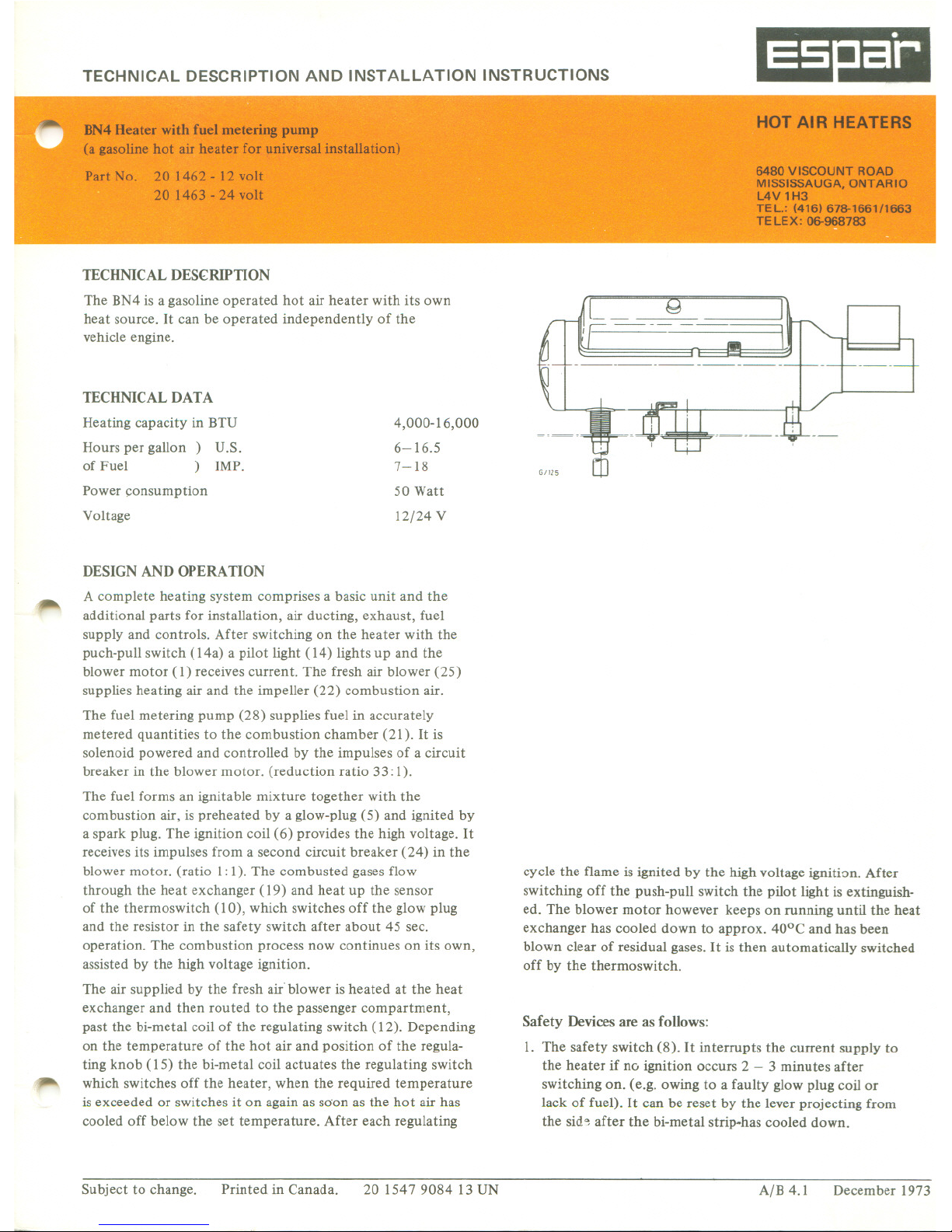
TECHNlCAL DES(RIPTION
The BN4 is a gasoline operated hot air heater with ils own
heat source. It cao be operated independently of the
vehicle engine.
TECHNlCAL DATA
Heating capacity in BTU
Hours peTgallon) U.S.
of Fuel ) IMP.
4,000-16,000
6-16.5
7-18
50 Watt
Power çonsumption
Voltage 12/24 V
DESIGNAND OPERATION
~
A complete heating system comprises a basic unit and the
additional parts for installation, air ducting, exhaust, fuel
supp1y and contro1s. After switching on the heater with the
puch-pull switch (14a) a pilot light (14) lights up and the
blower motor (1) receives current. The fresh air blower (25)
supplies heating air and the irnpeller (22) combustion air.
The fuel metering pump (28) supplies fuel in accurately
metered quantities to the combustion chamber (21). It is
solenoid powered and controlled by the impulses of a circuit
breaker in the blower motor. (reduction ratio 33: 1).
~
The fuel forms an ignitable mixture together with the
combustion air, is preheated by a glow-plug (5) and ignited by
a spark plug. The ignition coil (6) provides the high voltage. It
receives ils impulses from a second circuit breaker (24) in the
blower motor. (ratio 1: 1). The combusted gages flow
through the heat exchanger (19) and heat up the sensor
of the thermoswitch (10), which switches off the glow plug
and the resistor in the safety switch after about 45 sec.
operation. The combustion process DOWcontinues on ils own,
assisted by the high voltage ignition.
The air supplied by the fresh air°blower is heated at the heat
exchanger and then routed to the passenger compartment,
past the bi-metal coil of the regulating switch (12). Depending
on the temperature of the hot air and position of the regula-
ting knob (15) the bi-metal coil actuates the regulating switch
which switches off the heater, when the required temperature
is exceeded or switches it on again as soon as the hot air has
cooled off below the set temperature. After each regulating
HOT AIR HEATERS
.1
6480 VISCOUNT ROAD
MISSISSAUGA, ONTARIO
L4V 1H3
TEL.: (416) 678--1661/1663
TELEX: 06-968783
...
Il
6/125
cycle the flame is ignited by the high voltage ignition. After
switching off the push-pull switch the pilot light is extinguish-
ed. The blower motor however keeps on running until the heat
exchanger has cooled down to approx. 40°C and has been
blown clear of residual gages. It is then automatically switched
off by the thermoswitch.
Safety Deviees are as follows:
1. The safety switch (8). It interrupts the current supply to
the heater if no ignition occurs 2 - 3 minutes after
switching on. (e.g. owing to a faulty glow plug coil or
lack of fuel). It cao be reset by the lever projecting from
the sid~ after the bi-metal strip.has cooled down.
Subject to change.
201547908413 UN
December 1973
Printed in Canada.
A/B 4.1
Page 2
2. The overheating switch (11) interrupts the CUITentflow to
the fuel pump by short circuiting the 8 Amp fuse (9) if the
heater should overheat (e.g. owing to blocking of the hot
air ducts). After the cause of overheating has been
eliminated and a new 8 Amp fuse installed, the heater is
again ready to operate.
3. The static pressure in the hot air ducts is higher than in
the combustion cham ber and heàt exchanger. Owing to
this no exhaust gages can penetrate the hot air even if the
exchanger should be leaking.
~
12 13 ~.
I
~II;II.P415
L
140 Il ~
C" .111'-"~
'-'-'-'l
1-'
~
\ \ \
20 19 18 17
j
~
29 28
\
27
.~8
26
~
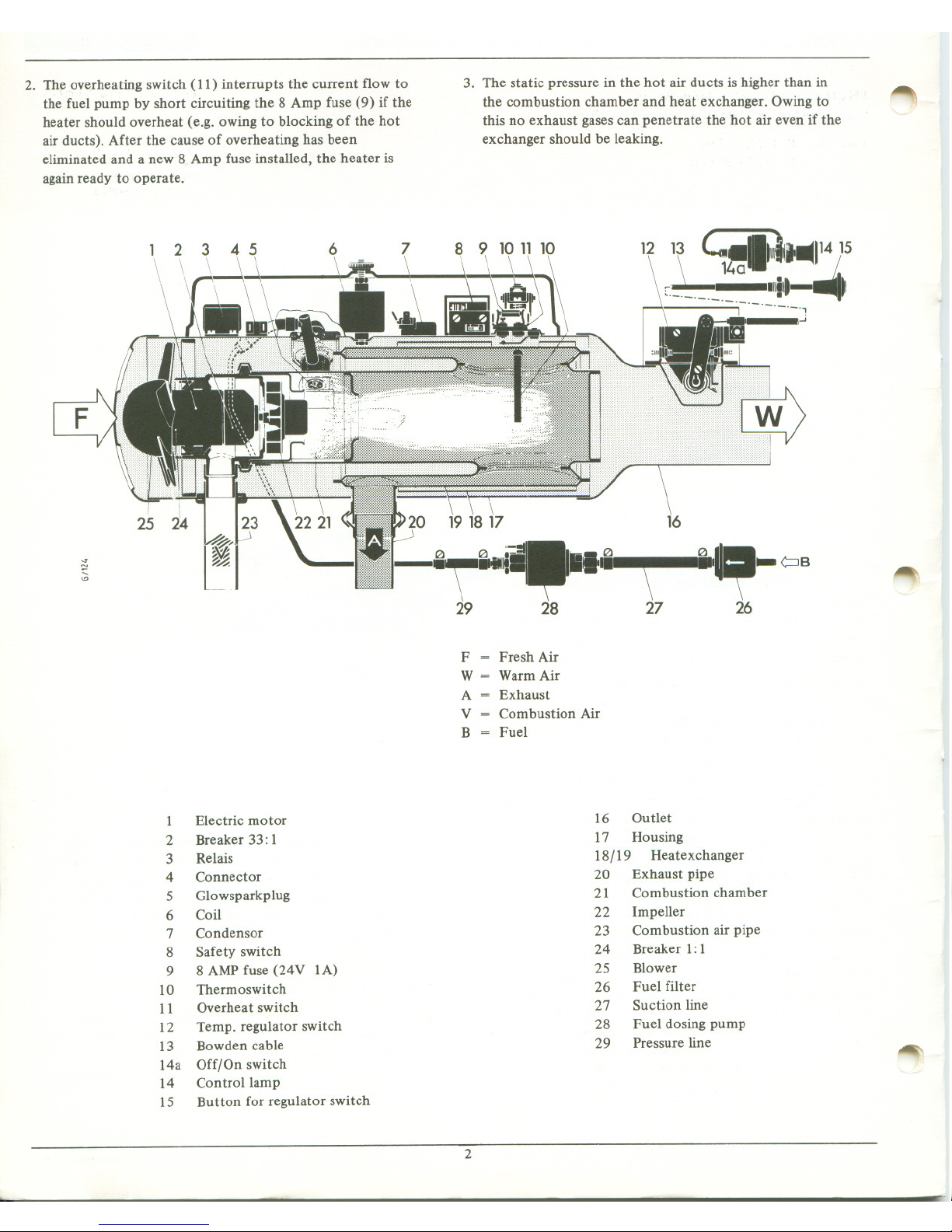
F = Fresh Air
W = Warm Air
A = Exhaust
V = Combustion Air
B = Fuel
1 Electric motor
2 Breaker 33: 1
3 Relais
4 Connector
5 Glowsparkplug
6 Coil
7 Condensor
8 Safety switch
9 8 AMP fuse (24V lA)
10 Thermoswitch
Il Overheat switch
12 Temp. regulator switch
13 Bowden cable
14a Off/On switch
14 Controllamp
15 Button for regulator switch
16 Outlet
17 Housing
18/19 Heatexchanger
20 Exhaust pipe
21 Combustion chamber
22 Impeller
23 Combustion air pipe
24 Breaker 1:1
25 Blower
26 Fuel fiUer
27 Suction line
28 Fuel dosing pump
29 Pressure line
~
2
Page 3
~
OPERATION
SwitchingOn Heater
Pullout the pull-pushswitch. The pilot light corneson and
indicates that the heater is switched on.
SwitchingOff Heater
Pushin the pull-push switch. The pilot light goesout. The
2 - 3 minute cleaningcycle ends automatically.
Operatingwith Room Thermostat
To keep the passengercompartment temperature constant
a room thermostat cao be installed.
The heater is started by pulling the pu11-push switch. The
pilot light then cornes on. As soon as the temperature which
bas been set at the thermostat bas been reached, it switches
the heater off. After the temperature bas dropped, the
thermostat switches the heater on again.
The heater remains off when the push-pull switch is pushed
in and the pilot light is extinguished. The cleaning cycle
always follows to cool the heating system down and to
clean out a11residue gages.
~
MAINTENANCE
Please switch the heater on during the warm season (once a
mon th) for a short period to avoid gumming,up of the fuel
line.
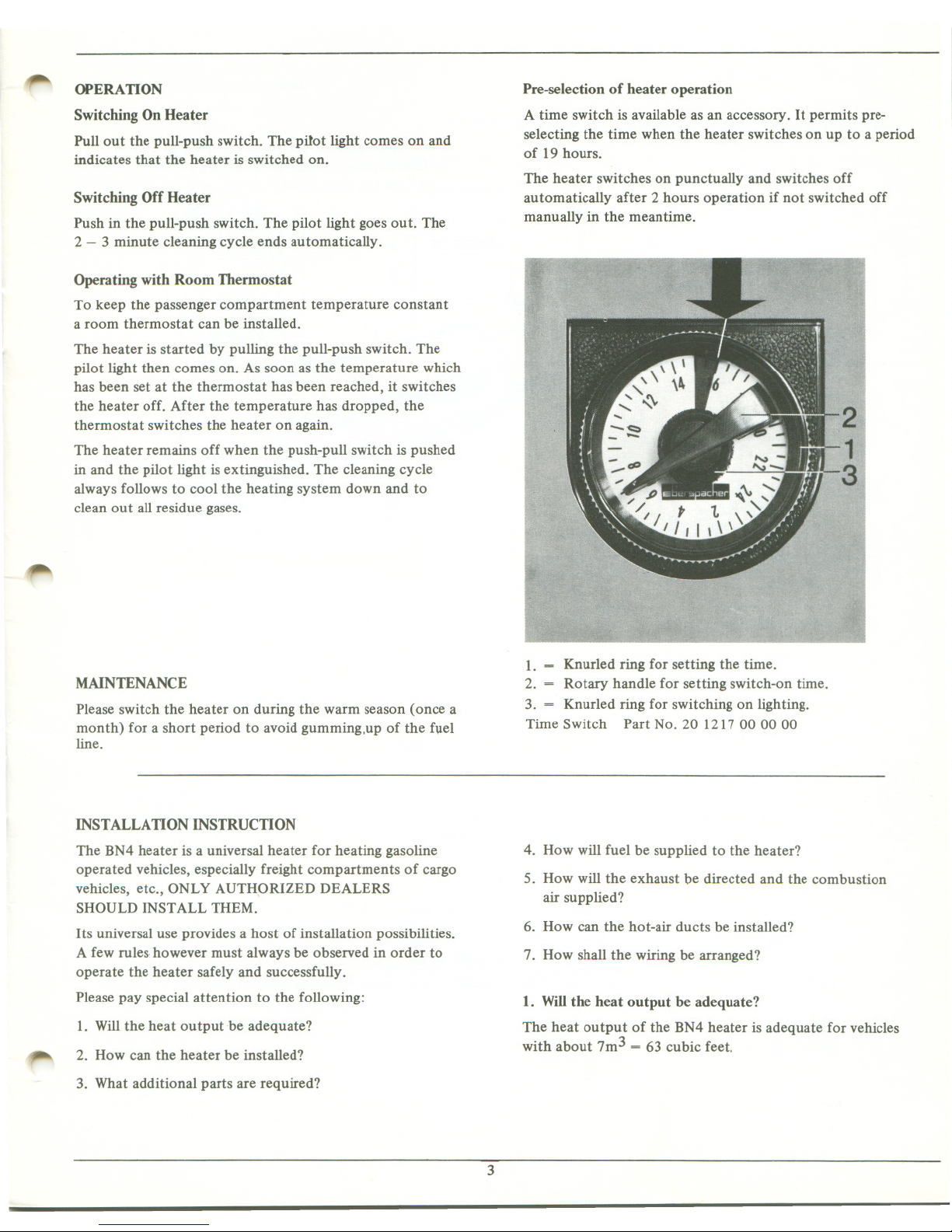
Pre-selection of heater operation
A time switch is available as an accessory. It permits pre-
selecting the time when the heater switches on up to a period
of 19 houes.
The heater switches on punctually and switches off
automatically after 2 houes operation if Dot switched off
manually in the meantime.
1. = Knurled ring for setting the time.
2. = Rotary handle for setting switch-on time.
3. = Knurled ring for switching on lighting.
Time Switch Part No. 201217000000
INSTALLATIONINSTRUCTION
The BN4 heater is a universal heater for heating gasoline
operated vehicles, especially freight compartments of cargo
vehicles, etc., ONLy AUTH9RIZED DEALERS
SHOULD INSTALL THEM.
Its universal use provides a host of installation possibilities.
A few mIes-however must always be observed in order to
operate the heater safely and successfu11y.
Please pay special attention to the fo11owing:
1. Will the heat outputbe adequate?
~
2. How cao the heater be installed?
3. Whatadditional parts are required?
4. How will fuel be supplied to the heater?
5. How will the exhaust be directed and the combustion
air supplied?
6. How cao the hot-air ducts be installed?
7. How shall the wiring be arranged?
1. Willthe beat output be adequate?
The heat output of the BN4 heater is adequate for vehicles
with about 7m3 = 63 cubic feet.
3
Page 4
.
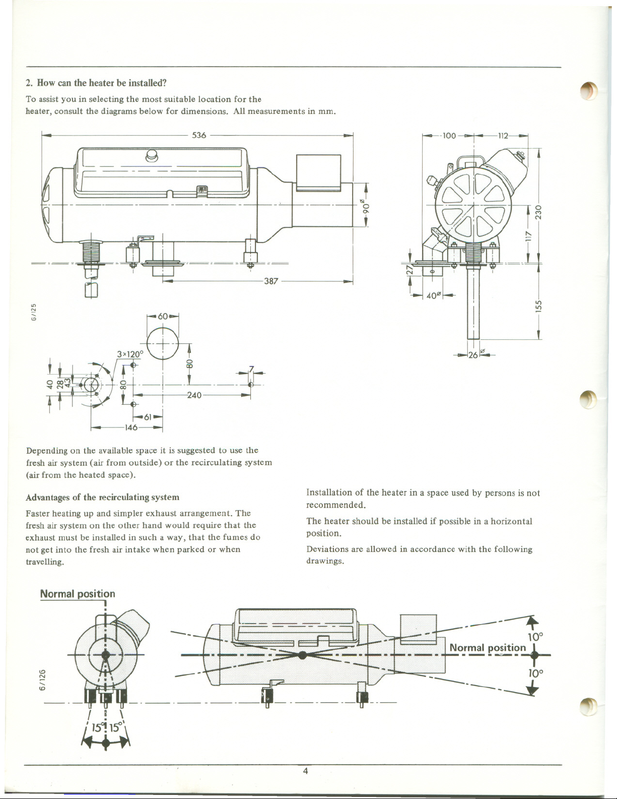
2. Dow can the heater be instaUed?
To assist you in selecting the most suit able location for the
heater, consult the diagrams below for dimensions. AlI measurements in mm.
536
----
----
----
387
on
N
Depending on the available space it is suggested to use the
fresh air system (air from outside) or the recirculating system
(air from the heated space).
Advantages of the recirculating system
Faster heating up and simpler exhaust arrangement. The
fresh air system on the other hand would require that the
exhaust must be installed in such a way, that the fumes do
Hot get into the fresh air intake when parked or when
travelling.
Normal position
1
.
~
l
If
'IS!
0
0.
1
1
-j
"
b:tli
1
1
~-
-J26 L
l
1/")
~
~
Installation of the heater in a space used by persons is Hot
recommended.
The heater should be installed if possible in a horizontal
position.
Deviations are allowed in accordance with the following
drawings.
10
~
.....
(j)
1 1 \
. ,
~
:t
10°
No!~ po~iti~~
10°
*
~
4
Page 5
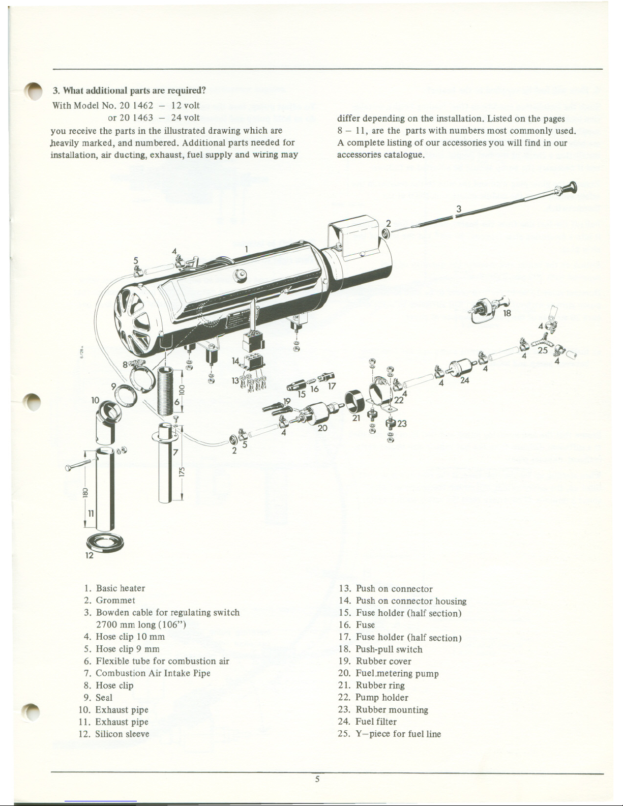
~ 3. Whatadditionalparts are required?
With Model No. 20 1462 - 12 volt
or 20 1463 - 24 volt
fOU receive the parts in the illustrated drawing which are
heavily marked, and numbered. Additional parts needed for
installation, air ducting, exhaust, fuel supply and wiring may
differ depending on the installation. Listed on the pages
8 - Il, are the parts with numbers most commonly used.
A complete listing of our accessories fOU will find in our
accessories catalogue.
~
~
--
"~
11
p
~
1. Basicheater
2. Grommet
3. Bowdencablefor regulating switch
2700 mm long (106")
4. Hose clip 10 mm
5. Hoseclip 9 mm
6. Flexible tube for combustion air
7. Combustion Air Intake Pipe
8. Hose clip
9. Sea1
10. Exhaust pipe
11. Exhaust pipe
12. Siliconsleeve
13. Push on connector
14. Push on connector housing
15. Fuse holder (half section)
16. Fuse
17. Fuse holder (half section)
18. Push-pull switch
19. Rubber cover
20. Fuel.metering pump
21. Rubber ring
22. Pump holder
23. Rubber mounting
24. Fuel filter
25. y -piece for fuelline
5
Page 6

4. How will fuel be supplied to the heater?
Since the installation conditions (fuel feeding height, installa-
tion location, length of fuellines etc.) influence the fuel
supply to the metering pump to a certain extent, the pumps
are only preadjusted by the manufacturer. After successful
installation a check of the fuel supply must be carried out
and if necessary thè pump should be adjusted as follows:
Remove the glow plug wire and the wire to the resistor in the
safety switch from the middle connection (NO) at the
thermoswitch.
Pull off the fuelline from the heater, bleed the line and place
it into a measuring glass (approx. 20 cm3.) at the level of the
glow plug.
Switch on the heater and measure the quantity of fuel
supplied with 200 pump strokes.
Nominal value 13 to 15 cm3. ln order to be able to count the
pump strokes without difficulty, it is advisable to mark off
each 20 strokes of the pump on a piece of paper.
a) Installation of the fuel metering pump and the fuelline
between pump and heater.
Ensure that the fuel metering pump and fuellines are installed
at a sufficient distance from the hot vehicle and heater parts.
(exhaust, exhaust pipe).
When starting up for the first time, if the fuelline is not yet
filled op, the safety-switch will switch the heater off after
about 3 minutes. If necessary reset the safety-switch again.
~
To adjust pump, tum the valve body (1) 1/4 to 1/2 tom. To
do so hold pump and loosen the lock nut (2).
Pressure side Suction side
Tum left to increase
Tum right to decrease the quantity
Remeasure and continue to adjust until the nominal value
has been reached. When tightening the lock nut ensure that
the valve body is not also tumed. Finally geai the lock nut
with paint.
~
~
~+ .
.~
'.s-~ .
r.s-
"
'..I~
".9
~
a.
c
~
6
Page 7

~
b) Fuel connection for vehicles with carburetor engines.
---------
---------
---------
---------
---------
- - - - - - - --
max. 20 in. ---------
- - - - - - ---
---------
---------
---------
- - - - - - - --
~'O healer
~ '" "';d. ."'~ ~
1 -~ -.~-~-
~--------
-------
pump below min. fuel
level or al max. of
4 in. above
max. 17 fI. long, if pump below min. fuel level
max. 4 fI. long, if pump above min. fuel level (al max.4 in.l
~
c) Fuel connection for vehicles with fuel injection engines.
1
maximum----.
,--_~-_~fuellevel- --
------
---------
----
---------
-------
- - - - --
max. 20 in.
---------
- - - - - - ---
---------
---------
-~-----
--- -------
pump below min. fuel
level or al max. of
4 in. above
max. 17 fI. long, if pump below min. fuel level
max. 4 fI. long, if pump above min. fuel level (al max.4 in.l
~
7
Page 8

d) Fuel connection for a very high tank (level regulator
necessary).
~
---------
---------
to tank vent
---------
~---
if
------
- - - - - - - --
-------
------
--------
-------
over 20 in.
------
--------
-------
--------
minimum
fuel level - 7" -::
- .--=-=-= :-_-
~toheater
1
1
. L.~" ~
~
.
--~ --
1
evel regulator always
-. ..1 below the minimum
-- fuel level
t fi) max.4 in.;..
~ ~11ti---1~
~ max.4ft.long
r:
e) Fuel connectiQn if the metering pump has to be installed
higher than lOOmm above the minimum fuellevel, or if the
suction Hne is longer than 1.2 m.
ç8~---
~
...L ~
L-:::;:~~: ---1
:s:z.maximum -
=- -= fuel level --
- --- - - - - --
- - - - ---
max.40in.
- ------
--------
t
~
l
- --- - - - - --
- - - - - ~ --
- - - - - ---
tr
",-,
1--2.. minimum
- :-=- = !.u~1'~vel~
------
-- --
8
Page 9

~
f) Accessories for Fuel Supply
O
~
~
Ventmg
""
"".""
Pipe .'
-"
4 --
... ,,',
~S.c: ~~ r- ~
.J-o_~~:::]~ ) , Ir~~
- [cc;:~;;#;;~ .,: &1 ~ "
f(fJf!À'
~
\) / "\\-~! lA.
I~~Y::
,
'~
,
. \ \ , ,.J;P&«iP ~ 1it' _01\\
,
7
,
, 13
2\\~~
~
(~, 1 <8>
,
~
&
~
~
,
'- &
~
,'!&"!J,' , ' ..~~"' "' ' 10.,.-,
~ '~"
11 tn>
V,nting ~ 1
12 ~ Pipo U
3& ~
12&~ ~ \
,..----
f
~
DiagramNo.
1
2
3
4
5
5a
6
7
8
9
10
~
Il
12
13
14
15
16
Name
fuelline
stee1line
fuelline
1eve1regulator
y piece (for vehicle fuelline)
y piece (for vehicles with fuel injection)
y piece (for vehicle fue1line)
pump bracket
hose fitting straight
capnutM10X1
fuel pump
hose fitting 90° with capnut M 10 X 1
hose clamp
fuel tank connection
fuel tank
fuel tank
fuel tank
15
Dimensions etc.
5/16 aD, 1/8 i.d. 9'>lin. H.
5/32 ID, 1.16 i.d. 9'>lin. H.
3/8 aD, 3/16 i.d. 9'>lin. H.
12 V. 0.1 aille = 1.411bs. psi
24 V. 0.1 aille ~ 1.411bs. psi
15/32" 9'>
7 liter ca 1 1/2 gallons
7 liter ca 1 1/2 gallons
4 liter ca 1 gallon
Part No.
36075 110
049 10 004
36075 130
25 85~5 360000
20 1307 02 06 00
20 1316 02 01 00
25 1202 03 01 00
20 8546 07 00 27
250187000000
116 10002
201122040100
201123040100
25 1156200300
102061 01 0090
25 1156270000
20 1462 89 10 00
20 146289 20 00
20146289 1500
9
Page 10

S. Dow will the exhaust be directed and the
combustion air supplied?
Exhaust and combustion air intake must be balanced to ensure
a smooth, soot-free combustion process. Make sure that no
combusted air enfers the fresh air intake while fOU are
driving or parked. It is important that the heater does not
interfer with vital parts of the vehicle, (brake lines, fuel
lines etc.). The combustion air must be picked up from the
outside.
Therefore, please observe the following:
a) Should the supplied exhaust pipes have to be extended, an
elbow with an injector should be installed first. You can
then connect a pipe up to 3 ft. to if. A further extension
requires the installation of an exhaust blower, to which
a pipe up to 6 ft. can be attached. The cross section
(55 mm 1/>,2 5/32") of the pipe must not be reduced.
b) The maximum permissible length of the combustion air
intake pipe is 600 mm. (23.4").
c) Exhaust and combustion air intake must be located in
such a way that no exhaust fumes can be sucked in by
the combustion air intake.
d) The exhaust pipe and combustion air intake pipe must be
located in a similar pressure area. At aIl speeds the
differential pressure between the combustion air intake
and exhaust outlet must not exceed +4 mm WC(5/32")
(max. over pressure at exhaust pipe) and - 4 mm WC
(5/32") (max. under pressure). Solder close to the heater
one tube 1/16" 1/>i.d. to the combustion air pipe and one
1/16 1/>i.d. to the exhaust pipe.
At least 2" of pipe must be allowed beyond 'the measuring
point. Drill a 1/16" hole through both pipes and deburr them.
The tubes are connected by hoses to a manometer (e.g. U-tube)
at which the differential pressure can be read off. By moving
the exhaust pipe and the combustion air intake pipe to
another location or by cutting the pipes diagonally the
pressure differential can be influenced due to a change of
speed. Do not install the exhaust pipe facing the direction
of trave!.
~
N
~
(0
0 Desirable value
~
-4mmWS
0
Maximum allowable
vacuum at exhaust pipe
Maximum allowable
over pressure at exhaust pipe
~
10
Page 11

.
~
Accessories for exhaust and combustion air intake.
?\
5
~
~
~
p
Diagram No.
1
2
3
3a
4
5
6
Name
Flexible Combustion Air Intake Pipe
Seal
Combustion air intake pipe
Dimensions etc.
1 1/32" If>I.D. in fi.
Part No.
102112020000
20 1282 20 00 00
047 05 023
20 1121 07 01 00
25 8585 33 03 00
047 05 069
25 1202 24 00 00
25 1202 25 00 00
1 1/32" If>O.D. in fi.
Exhaust Elbow with Injector
Exhaust Pipe
Exhaust Blower
25/32" If>I.D.
12 volt
24 volt
,.,...
Il
Page 12

6. How can the hot air ducts be installed?
The resistance of the hot air ducts (wall friction and losses
due to variation in direction) and the outlet and intake hood
should Dot exceed a static pressure of 6mm WC 0/4" WC).
This resembles a 9ft. flexible pipe with 90mm = 3 9/16" i.d.
with 1 or 2 bends and with an outlet and intake hood. Hot
air ducts should Dot exceed the above 1engths (minimum
cross section 64 cm2 = 90 mm i.d. = 3 9/16" i.d.)
1"
Witha fresh air system draw in the fresh air from a level as
lllgh as possible, Dot in the region of the exhaust, and Dot
from a location which is un der ram-air pressure or vacuum.
With a recirculation system, locate the circulating air intake
so that the outflowing hot air cannot be directly drawn in
again.
Insulate hot air ducts installed in the open against heat loss.
3~
+-'-'-'
" i i
! i
! i
1 i _.~ ,
. .
~
l
! ! i
'1 1 ~." "~~" ~"
-
1
~ '. \\;/1
.
' \-
. ~ 1
i \
~
,!\v,lj
~
! \, \_~
\ \ \
2 - - \.
1
""
90 mm I.D. in ft.
Part Number
20 1127 010101
25 8585 29 00 00
la 2060 09 51 52
10 2112 15 00 00
20 1297 00 00 al
20 1297 00 0100
20 146289 06 00
20 146289 02 00
~
No.
1
2
3
4
5
6
7
8
Description
Hood
E1bow
Clamp
Flexible duct for hot air
F1ange for flexible duct
Screen
Spherica1 E1bow .Left
Spherical Elbow Right
Measurements and other Data
12
Page 13

,..
7. How shaHthe wiring be arranged?
CORRectthe heater to the power supply according to the
wiringdiagram(check the voltage).
1
1:-
Ir--
- --
The additional coRRection of a time switch and a room
thermostat is indicated by dotted liRes.
1
1
\
\ 1
I~
.j:
~~
","
~;-:-
Ground strap with ...;-..,-='
radio supressor ,,;',~--
models only ,"'di
d:'
À
"..
Wiringdiagramfor BN4 heater
WITHOUTventilation
~
1
1
1 1
3
) !
,/' 1
/ 1
i 7
Ground
',5(4)' ,od ('2."5(4)"Od--O +Batte"l
12red .r ,
4~:
.,.,.,.} ... ~.. c.. 'i :
;;;~' 1
l',' lighting 1
--j/l~
~
.~',\~
5
\~~1~JJJ
~--1
"
~
Cross sections in 0 for duct lengths over 4 m ~ feet
~
To CORRectthe room thermostat rem ove wire 0.5 grey
between switch and Six-coRRection plug.
AlI diameters given in sq. mm.
1
l
,
l
,
L-
6
1
2.5(4)2 brown
0 -Battery
0.52 grey
[Q]2
1) Multi connector
2) Fuse holder
3) Fuel metering pump
4) Off/On Switch
5) Timer (accessory)
6) Room thermostat (accessory)
13
Page 14

Wiringdiagram for BN4 heater WITH ventilation
1"
-
- -
Ground strap with
radio suppressor ,
models only '"
~
1
0 -Battery
~
:b
.
1 1
1 1
3
J l
, 1
~
/ l
,/'
.<f~
(/~
1 7
lGround
'"
Il'I
ci
1
1
.
1
.
L-
6
[92
'~4
0.5black/whiteB ' 1 Il "-
1 l "-
/,. -1 ,
, ( Lighting 1
/I~I
-_/ ~~
O,S2grey
f8'Iit
14
Page 15

~ Accessoriesfor electrical installation and controls
A
~
DiagramNo.
1
2
3
4
~
,~
~
2
---~
3
4
JJO~)
';;';é"-'
Dimensions etc. Part No.
Name
Room thermostat
Timer
Bowden cab1e for temperature contro1 switch
Off/On Switch
25 1179320000
20 134803 1600
13 ft. 20 1104260001
12 volt (heating & ventilatiOn)
}
20 1121 090001
24 volt (heating & ventilation)
15
Page 16

BN4 - Compact Heater - l2V Model No. 20 1547
24V Model No. 20 1548
...-
These heaters are already equipped with the following
accessories: Metering pump, electric fuel pump to overcome
greater suction heights, fuel fiUer, and rubber mounting, all
premounted. ln addition the following parts are inc1uded:
2. Grommet (2) for fuelline and wiring harness
3. Bowden cable for regulating with 2700'
4. Clamps (39/16" - 4 5/16")
5. Clamp
6. Gasket
7. Exhaust Elbow
8. Exhaust pipe
9. Silicon geai
10. Flexible combustion air intake pipe
Il. Combustion air intake pipe
12. Hexagon nuts & washers
13. Wiring harness 15 feet with 16 Amp fuse
14. Push-pull switch
00
~ -Battery
~ +B_~
,..
,
b
@
12
~
Operation
The wiringharness has to be installed according to the above
diagram.
90
To bleed the fuelline proceed as follows:
Unscrew the hollow screw at the outlet of the electric fuel
pump (Arrow). Start heater. As soon as fuel emerges tighten
hollow screw again.
~
16
.
 Loading...