

Page 1
Multifunction (7 Day Timer) Manual
Installation Instructions
Operating Instructions
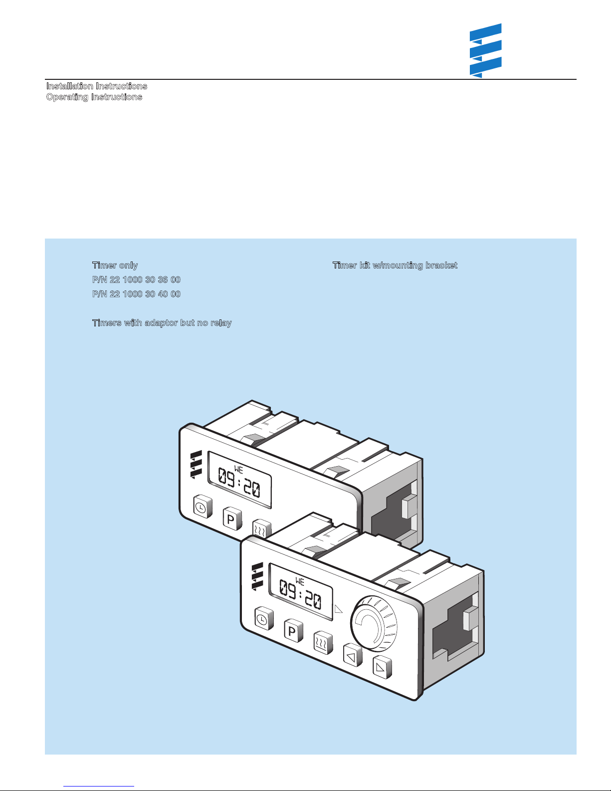
Timer only
P/N 22 1000 30 36 00
P/N 22 1000 30 40 00
Timers with adaptor but no relay
P/N 20 2900 70 02 01 (Coolant heater 24 volt)
P/N 20 2900 70 02 10 (Air heater 12 volt)
(Coolant heater 12/24 volt)
(Air heater 12/24 volt)
Espar Heater Systems
Espar Products, Inc.
6099A Vipond Drive
ississauga, Ontario
M
Canada L5T 2B2
(905) 670-0960
(800) 387-4800 Canada & U.S.A.
(905) 670-0728 Fax
www.espar.com
Timer kit w/mou tinn g bracket
P/N 20 2900 70 02 30 (Coolant heaters)
P/N 20 2900 70 02 35 (Air heaters)
P/N
Coolant Heater
Air Heater
02.2008 Subject to Change Printed in Canada
Page 2
Instructions
76
1 2 3 4 5
9 10 118
9 1210 1176
1 2 3 4 5
8
7 Day Timer Instructions
The 7 Day Timer has been designed to provide a simple
means to control the operation of the heater system and to
include diagnostics capability. This timer connects to the
iagnostic circuit of the heater. The timer then displays any
d
heater fault codes in three digit number form automatically.
The timer allows for pre-selection of turn on time, up to 7
days in advance, as well as an option for run times up to 2
hours before automatically turning off. In addition, there is an
on/off switch for manual operation. By default the timer is preset by Espar to operate for two hours.
Mounting Bracket and Bezel
P/N 25 1482 70 01 00
Bezel
Mounting Bracket
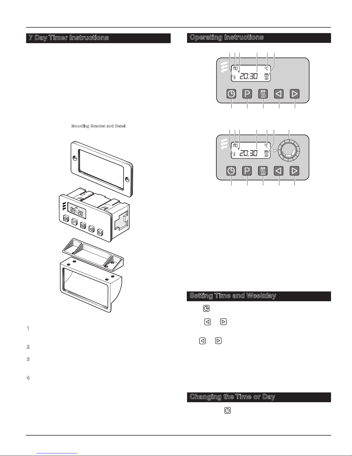
Operating Instructions
Coolant Heater
Air Heater
1. Timer Set
2. Pre-heat Time Set
3. Heater “ON”
4. Backward Scan
5. Forward Scan
6. Memory Display
7. Weekday or Preset Day
8. Symbol for Radio Remote Control
9. Current Time or Preset Time
10. Temperature Display
11. “Heat” Symbol
12. Temperature Preselection (Range 10-30oC
Air Heater only)
1
Mount bezel into dash and insert timer or use Espar’s
optional mounting bracket and secure to dash.
2
Neatly route and secure harness under dashboard.
3
Cut harness to length and terminate wires attach using
connectors provided. Insert terminals into housing.
4
Connect harness to timer.
2
Setting Time and Weekday
Push button once 12:00 will begin to flash (this will
occur upon initial hook up to power).
Using or set the present time of day (24 hour clock).
When the time stops flashing the time has been stored.
The weekday will now begin to flash.
Use or to set the present weekday.
When the weekday stops flashing the weekday has been
stored
When the vehicle ignition is turned “on” the time display will
appear
, if optional connection on pin 10 is insatlled.
When the vehicle ignition is turned “off” the timer display will
go off after 15 seconds.
Changing the Time or Day
Push and hold button until the time display begins to
flash.
Continue to set the time as listed in setting time and weekday.
Page 3

Instructions
P
P
Red
Brown
1
2
1
1 1
0
9
8
7
6
5
4
3 2
1
Red
Optional
Yellow
Grey/Red
Brown/White
Optional
Blue/White
Brown
a)
b)
c)
d)
e)
f)
h)
DIAG
1
2
1
1 1
0
9
8
7
6
5
4
3 2
1
TRS
Blue/White
Optional
DIAG
Red
Brown
Brown
1
2
11 10
9
8 7
6 5 4
3 2
1
Red
Optional
Yellow
Blue
Brown
TRS
a)
b)
c)
d)
e)
f)
Using the Timer with the Vehicle Ignition “Off”
Push button.
will appear on the display as well as the operation countdown timer.
The running time is factory set to maximum of 120 minutes.
his running time can be reset once or permanently as
T
desired.
Adjusting Preheat Time Once
Press button.
The will appear in the display and the preselected run
time will appear in the display (maximum time of 120 minutes).
Use the or to adjust the desired run time.
Adjusting the Heater Preheat Time Permanently
(Maximum Preheat Time of 120 minutes)
Push and hold (about 3 seconds) until the display lights
up and flashes. Release button.
Use or to set the new fixed preheat time.
When the display goes off the new preheat time is set.
Note:
At the end of a preheat cycle the timer will turn the
heater off. The heater will complete a cool down cycle and
turn itself off
Using the Heater Manually with the Vehicle Accesory “On”
(Optional wire on pin 10 is connected to the ignition lock)
Push buton.
The symbol will appear in the display next to the time of
day.
The time of day will remain displayed during ignition on operation.
The heater will function continually as long as the vehicle ignition is “On”.
When the vehicle ignition is turned “Off”
tinue to operate for an additional 15 minutes.
The run time can be altered by pressing the or buttons.
The heater can be turned off by pressing button.
the heater will con-
Set Preheat Times into Memory
Press button until the desired memory location is shown
in the display (Three memory locations are available).
Using the or buttons set the desired preheat start time
of day.
When the time stops flashing the time of day is set.
Using the or buttons set the desired day of the week.
When the day of the week stops flashing the day is set.
To Use Preset Start Times
Press the button until the desired memory location
ppears in the display.
a
The heater will start at the day and time displayed.
The display will go off in 15 seconds. The memory location
number will stay displayed (1, 2 or 3).
Note:
When preset is chosen this symbol will flash red.
To Turn Heater “Off”- All Modes
Press the button once.
The heat signal to the heater will be turned “Off”.
The heater will do a normal cooldown and turn itself “Off”.
Note:
When the vehicle lights are turned “On” the timer back-
light will come “On” also.
Note:
This timer is equipped to display fault code numbers if
the heater should shut down due to an operating fault. The
fault code will show in the timer display next to the flashing
heat wave symbol. This applies to all current model heaters
when the blue diagnostic wire is connected.
Note:
If the timer is purchased without the harness kit, the
following heaters will need a load relay intalled (D8Lc, D7W,
D12W, D24W and D30W),
These heaters carry a load on the switch wire. (i.e. fuel metering pump or solenoid valve).
Note:
An outside temperature sensor is available as an
option.
Coolant Heater Timer Connections
a) Power from battery “+”
b) Switch control to heater
c) Power from battery “-”
d) Diagnostic from heater
e) To vehicle dimmer switch for light display
f ) To vehicle ignition accessories for continuous operation of heater
and for unlocking heaters ECU
Air Heater Timer Connection
a) Power from battery “+”
b) Switch control to heater
c) Power from battery “-”
d) Diagnostic from heater
e) Temperature setting “+”
f ) Temperature setting “-”
g) T
h) To vehicle ignition accessories for continuous operation of heater
o vehicle dimmer switch for light display
and for unlocking heaters ECU
3
Page 4

Instructions
P
P
P
P
Wiring Connections at Connector
Terminal 1 Power from vehicle dash lights.
Terminal 2 Heater switch wire - Yellow wire.
Terminal 4 Connect to vehicle ground.
Terminal 6 Temperature setting “+” (air only).
Terminal 8 Heater diagnostic lead - blue wire.
Terminal 9 Temperature setting “-” (air only).
Terminal 10 To vehicle “ACC” accessory for continuous
overnight use, and for unlocking ECU.
Terminal 11 Positive power from heater - red “+”.
Terminal 12 Ground lead from heater - brown “-”.
Terminal 3,5,7 Left blank, not required.
5.
Press the key and hold it down and press the
key within two seconds and hold it down.
6. While holding down keys, turn ignition on and
wait until the following display appears:
7. Press the key to turn the heater off.
8. Press the key to turn the heater on.
9. Repeat step three. The following display appears:
10. The control unit lock is cancelled after three seconds
and the heater starts.
Control Unit Locking
The control unit may becomed locked due to one of the following conditions:
1. Overheat
cession, fault message F15 is displayed and the control unit is
locked.
2. Too many failed start attempts
many start attempts in succession (i.e. Fault 52), fault messsage F50 is displayed and the control unit is locked.
Unlocking Control Units and Erasing Fault Memory
Please Note!
The electrical connection for the ignition / accessory
wire to the timer terminal #10 must be in place.
1.
Turn on the vehicle ignition to activate timer display.
2.
Press the key. The current fault code (i.e. F15 or F50)
is now displayed.
3.
Press the key and hold it down and press the key
within two seconds. The timer is now in the retrieval mode.
4.
Turn off the ignition.
– If the heater overheats three times in succ-
- If the heater performs
Retrieving the Stored Fault Codes
1. Press the key. The heater is switched on.
2. Press the key and hold it down and press the
key within two seconds. The current fault code is now
displayed (Example: AF:64).
3. The stored fault codes (maximum of 5) can now be
retrieved using the arrow keys and (Example:
F1:64).
Please
NOTE!
Consult the Troubleshooting and Repair manuals for
code definition and corrective action. If the heater is
not being operated using the 7-day timer, fault code
retrieval can be obtained using the “Fault Code
Retrieval Device”, par
t number 20 2900 70 50 20.
Notes:
Note:
Highlight areas requiring special attention or clarification.
Caution
4
:
Indicates that personal injury or damage to equipment may occur unless specific guidelines are followed.
Warning:
Indicates that serious or fatal injury may result if specific guidelines are not followed.
Special Notes
Page 5

st Printing - Feb 2008
1
Printed in Canada
P/N:
A member of the Worldwide
Espar Products, Inc.
e
6099A Vipond Dr
Mississauga, Ontario
Canada L5T 2B2
(905) 670-0960 Canada
(905) 670-0728 Fax
(800) 387-4800 Canada & U.S.A.
www.espar.com
EEbbeerrssppääcchheer
iv
r
Group of Companies
 Loading...