

Page 1
Espar Products, Inc.
6099AVipond Drive
Mississauga, Ontario
Canada L5T 2B2
(905) 670-0960 Canada
(905) 670-0728 Fax
(800) 387-4800 Canada & U.S.A.
www.espar.com
A member of the Worldwide
Eberspächer Group of Companies
Remote Starter
Installation & Operating Instructions
Remote Starter Kit 12 Volt: P/N 20 2900 70 01 50
Remote Starter Kit 12 Volt: P/N 20 2900 70 01 56
Espar
Installation Instructions
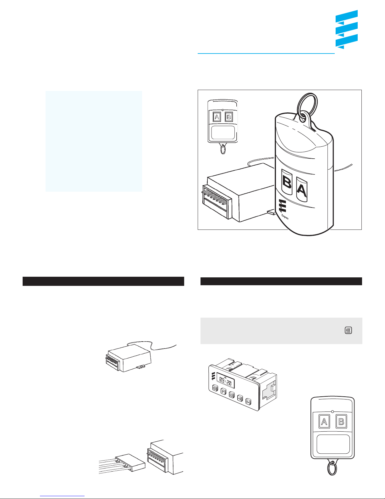
The remote starter has been introduced
to offer a simple and convenient way to
turn on the heater system within 300
feet of the heater. This remote starter
can be connected to the existing
harness of the of the 7 day timer or to
the timer directly. See schematics on
inside page.
1 Mount the receiver in a suitable place
under the dash near the operating
switch of the heater.
2 Run and secure the antenna as high
in the vehicle as possible, keeping it
away from metal surfaces.
3 Connect the harness to the receiver
and connect the other end to the
operating switch harness of the heater.
See schematics on inside page.
Receiver
P/N 5670035
Operating Instructions
7 Day Timer
Either the “A” or “B” button will turn the heater on and/or off.
Note: After turning the heater on via remote starter, you may,
at anytime turn the heater off with the off button on
the 7 day timer.
P/N 5670036
Control transmitter
A B
A B
Page 2
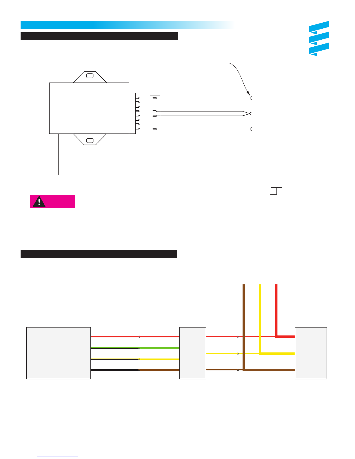
Schematics
7 Day Timer
Use remote Starter Kit 12 Volt: P/N 20 2900 70 01 50
Terminal
MINI.FE,AWG14-18
Espar Part Number
5670226
Espar
R964
RECEIVER
Espar Part Number
5670035
ANTENNA
For best range, uncoil and
place as high in vehicle as
possible and away from metal
surfaces as much as possible.
Warning:
Programmable Timer, Mini Timer, Thermostat & Rheostat
Disconnect heater’s harness, from battery
prior to making electrical connections
Red
Green / Black
Yellow / Black
Black
Pin 11 on Timer
Pin 7 on Timer
Pin 12 on 7 day Timer
7 day timer
P/N: 22 1000 30 36 00 (coolant)
P/N: 22 1000 30 40 00 (air)
Remote A - green wire pin 7 on timer
Remote B - yellow wire
Power - red wire pin 11 on timer
Ground - black wire pin 4 or pin 12 on timer
Use remote Starter Kit 12 Volt: P/N 20 2900 70 01 56
Heater Harness
Red
Green / Black
Receiver
1. Remove fuses on heater’s harness or disconnect from battery.
2. Connect four wires between relay and receiver as shown.
3. Connect tree wires from relay to harness:
• Red wire to fused red wire on heater’s harness going to control device.
• Brown wire to negative wire on heater’s harness (do not ground to chassis if vehicle has switch on battery “-”)
• Yellow wire of relay to yellow wire on heater’s harness.
3. Replace fuses.
Yellow / Black
Black / Brown
Red
Green
Yellow
Brown
R
e
a
y
Red
l
Yellow
Brown
Mini
Timer
 Loading...