

Page 1

Page 2

Table of contents
D7W Boxed
I. Introduction 1) General Specifications Page 1-5
2) Heater Warnings
3) Introduction
4) Principal Dimensions
5) Heater Components
II. Installation Procedures 1) Heater Location Page 6-15
2) Heater Mounting
3) Heater Plumbing
4) Fuel System
5) Electrical Connections
6) Exhaust Connection
7) Operating Switches
8) Optional Thermostat For Bunk Heat Exchanger
III. Heater Operation 1) Pre- Start Procedures Page 16-20
2) Start-Up
3) Running
4) Switching Off
5) Safety Equipment
6) Operational Flow Chart
7) Wiring Diagram
IV. Maintenance, 1) Recommended Periodic Maintenance Page 21-37
Troubleshooting & 2) Troubleshooting
Repairs 3) Fuel Quantity Test
4) Repair Steps
Appendix:
V. Heater Models 1) Principal Dimensions (25 1807) Page 38-48
Universal 25 1807 2) General Specifications (25 1666/25 1667)
25 1666 3) Location, Mounting, Plumbing, Fuel, Electrical, Exhaust
25 1667 4) Freightliner
Freightliner 5) Wiring Diagrams
VI. Heater Parts Section 1) Parts Diagram - Main Heater Components Page 49-59
2) D7WBoxed - Parts Diagram
3) Universal - Parts Diagram
4) Parts & Accessories Diagram
5) Description & Part #’s
Special Notes
Note: Highlight areas requiring special attention or clarification.
Caution: Indicates that personal injury or damage to equipment may occur unless specific
guidelines are followed.
Warning: Indicates that serious or fatal injury may result if specific guidelines are not followed.
Page 3

2
1. General Specifications
Model 25 1807 05
Heat Output (±10%) 24,000 BTU (7 Kw) -High
6,000 BTU (1.75 Kw) -Low
Current at 12v (±10%) 24.6 amps/hr - Start (1-2 minutes)
5.8 amps/hr - Running High
4.2 amps/hr - Running Low
Fuel Consumption (±5%) High Low
Heat Heat
US Gal/hr 0.24 0.06
Litre/hr 0.90 0.22
Coolant Pump Flow (±10%) 420 US Gal/hr
1600 Litre/hr
Coolant Temperature 176° F to 201° F (80° C to 95° C)
Range (±5%)
Overheat Temperature 275°F (135°C)
Shutdown (±10%)
Low Voltage Shutdown 10.5 Volts
High Voltage Shutdown 15 Volts
Page 4
2. Heater Warnings
Warning To Installer: Correct installation of this heater is necessary to ensure safe and
proper operation. Read and understand this manual before
attempting to install a heater.
Warning - Explosion Hazard
- Heater must be turned off while re-fueling.
- Do not install heater in enclosed areas where combustible fumes may be present.
- Do not install heaters in engine compartments of gasoline powered boats.
Warning - Fire Hazard
- Install the exhaust system so it will maintain a minimum distance of 2” from any flammable or heat
sensitive material.
- Ensure that the fuel system is intact and there are no leaks.
Warning - Asphyxiation Hazard
- Route the heater exhaust so that exhaust fumes cannot enter any passenger
compartments.
- If running exhaust components through an enclosed compartment, ensure that it is vented to
the outside.
Warning - Safety Hazard on Coolant Heaters Used With Improper Antifreeze Mixtures
- The use of ESPAR coolant heaters requires that the coolant in the system to be heated contain a
proper mixture of water and antifreeze to prevent coolant from freezing or slushing.
- If the coolant becomes slushy or frozen, the heater’s coolant pump cannot move the coolant
causing a blockage of the circulating system. Once this occurs,
pressure will build up rapidly in the heater and the coolant hose will either burst or blow off at the
connection point to the heater.
- This situation could cause engine damage and/or personal injury. Extreme care should be taken
to ensure a proper mixture of water and antifreeze is used in the coolant system.
- Refer to the engine manufacturer’s or coolant manufacturer’s recommendations for
your specific requirements.
Note: During electrical welding work on the vehicle disconnect the power to the heater in order to
protect the control unit.
Failure to follow all these instructions could cause serious or fatal injury.
Direct questions to Espar Heater Systems USA 1-800-387-4800
CDA 1-800-668-5676
3
Page 5
3. Introduction
The Espar D7W is a diesel fired 24,000 BTU/hr
coolant heater, quality engineered to provide a
dependable means of engine and sleeper heating. The heater can be purchased either in a
weather-resistant steel box to protect it and provide for ease of installation or in a universal form.
The heater simply pumps coolant from the
engine, heats it and returns it to the engine.
When used to provide sleeper heat, the coolant
is pumped through the sleeper heat exchanger
prior to returning to the engine. Since the heater
runs on diesel fuel and 12 volt power, it is able to
perform this completely independent of the vehicle engine. A temperature regulating switch in
the unit senses the coolant temperature and regulates the heater between a low of 176°F (80°C)
and a high of 201°F (94°C).
4
The heater may be operated from the vehicle cab
by a push/pull switch, a pre-select timer or a
combination of both.
The temperature sensor and overheat switch
form only a part of the safety features which
make this heater a safe and dependable unit.
Page 6
4. Principal Dimensions
D7W Boxed Model 25 1807
Figure 1A
5
8.25”
10.75”
15.25”
Page 7
5. Heater Components
Figure IB
6
Page 8
II. Installation Procedures
1. Heater Locations
Select the best mounting location while adhering to
the following conditions:
- Situate the heater below the normal coolant
level of the engine.
- Guard against excessive road spray.
- Keep coolant hoses, fuel lines and electrical
wiring as short as possible.
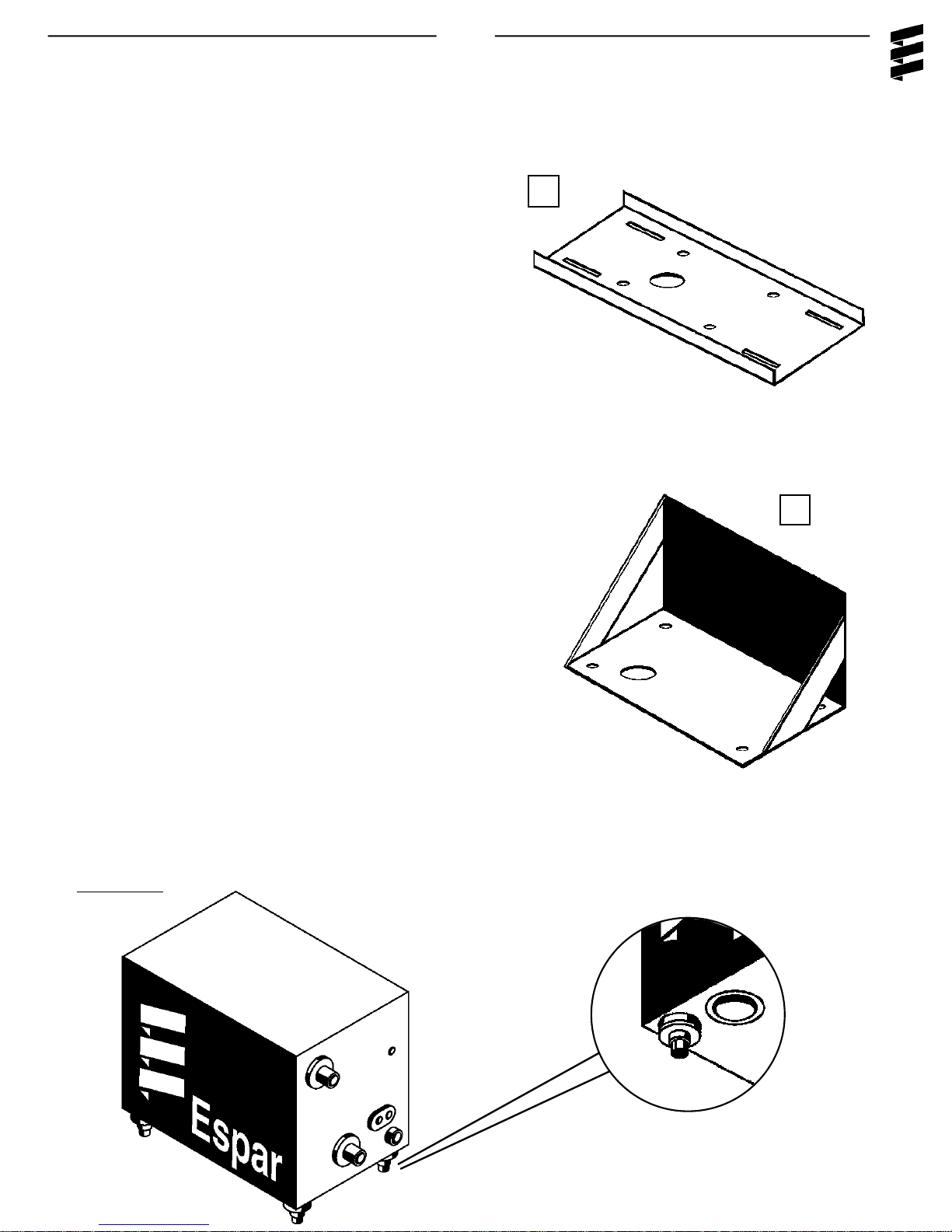
2. Heater Mounting
Mount the heater using the four (4) shock mounts
provided and one of the following mounting
methods: Figures IIA.
- Use the Cross Frame Mounting Tray (A) to
mount the heater behind the cab and on top
of the frame rails.
- Use the Side Mount Bracket (B) to mount the
heater on the side of the frame rail.
7
A
B
- Use a spare step box or battery box.
Figures IIA
Page 9
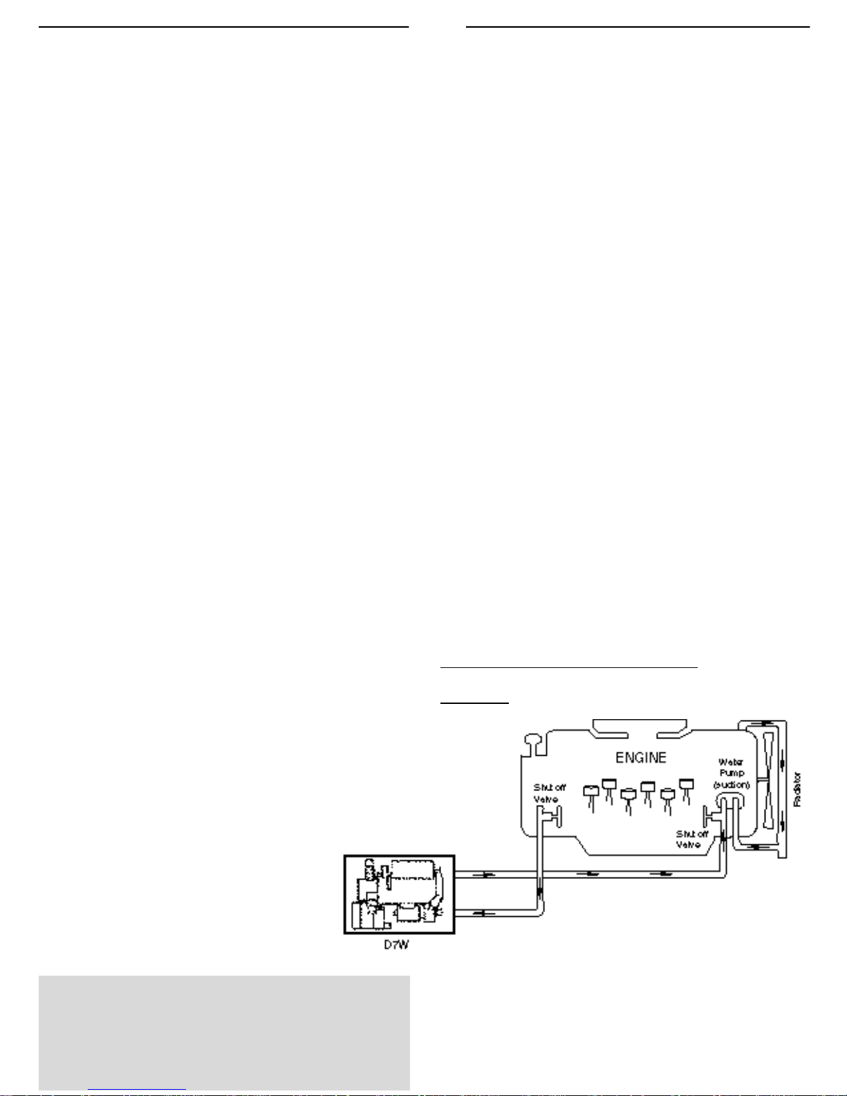
3. Heater Plumbing
8
Connect the heater to the the engine coolant system while considering these following points
- Install hose fitting in existing holes in the engine
block (these will have blanking plugs in them).
- Full flow shut off valves should be installed on
the pickup and return hoses at the engine.
- Alternatively “T” piece connectors in existing
coolant hoses can be used if no blanking plugs
are available
- Ensure proper coolant flow by using a minimum
of 3/4” hoses.
- Keep the coolant pick up point as low as
possible on the engine to reduce air in the
system.
- Take coolant from a high pressure point and
return it to a lower pressure point. (eg. back of
block to suction side of water pump).Ensure
that engine and heater are pumping fluids in the
same direction.
Caution: If your bunk heater exchanger has a flow
control valve integrated into it, provisions
must be made to ensure that flow through
the Espar heater cannot be blocked.
- Ensure proper heat distribution by keeping pick
up point and return point as far apart as
possible.
- Check flow rate through heater by measuring
the incoming coolant temperature and the out
going temperature. The rise in temperature
should not exceed 18°F (10°C). If the
temperature rise exceeds 18°F (10°C),
modifications should be made to increase the
flow rate. Check for restrictions in heat
exchanger and fittings.
- If a bunk heat exchanger is incorporated into the
system, proper plumbing layouts must be
followed. (Refer to Figure II B and Figures IIB 1
on following page for specific guidelines.).
D7WB plumbed for engine pre-heat
Figure IIB
Note: The coolant must contain a minimum of
10% antifreeze at all times as a protection
against corrosion. Fresh water will corrode
internal heater parts.
Page 10
When being used to provide bunk heat with a heat
exchanger the D7WB should be plumbed and wired to
one of the following methods.
1. D7WB plumbed with an
Espar heat exchanger.
9
Figures IIB1
2. D7WB plumbed with an
OEM heat exchanger.
Note: By pass must be used to ensure that
coolant flow can’t be completely stopped.
D7W Thermostat Options
1. D7WB wiring schematics for
the Espar heat exchanger.
2. D7WB wiring schematics for
OEM heat exchanger.
Page 11
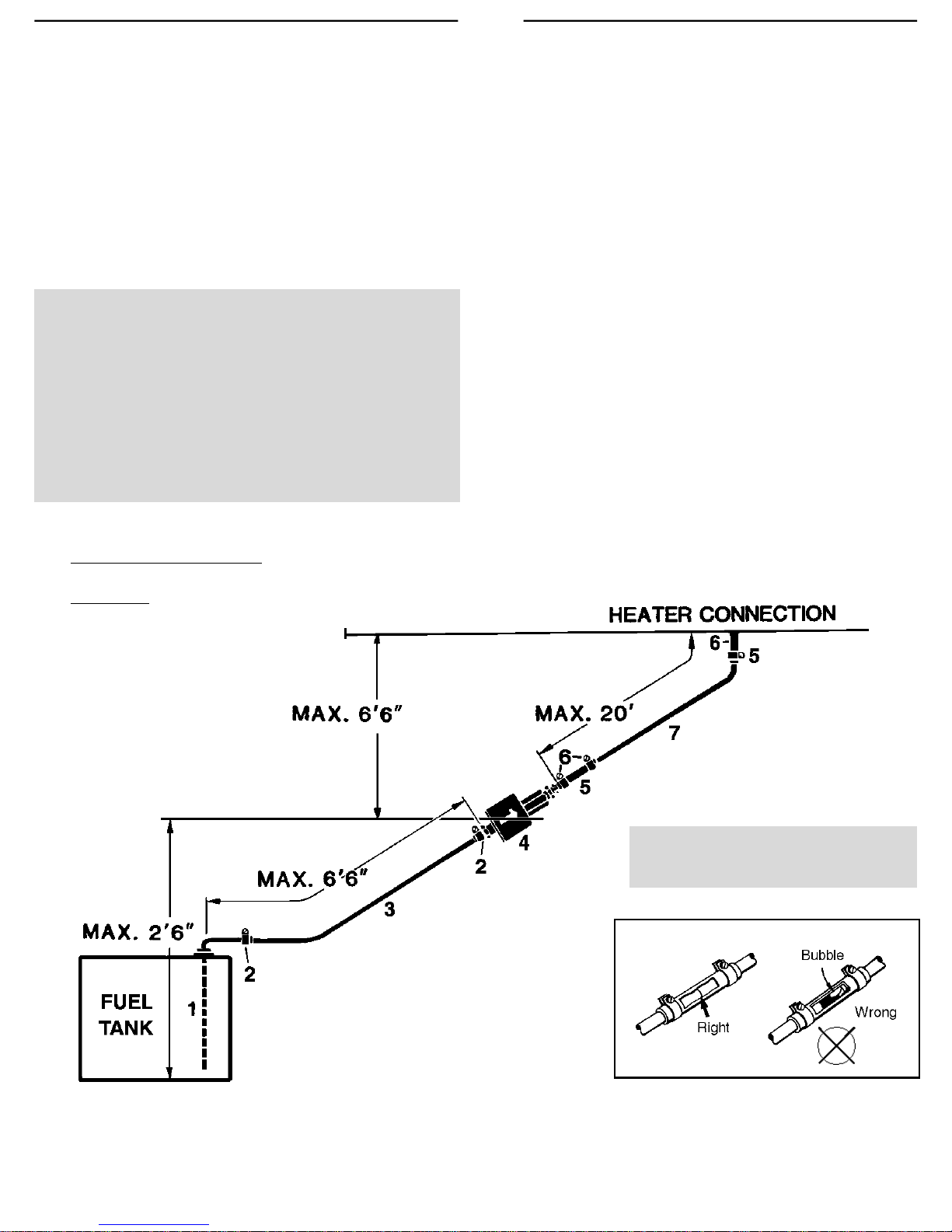
4. Fuel System
The D7WB is most commonly provided with the
fuel metering pump mounted inside the box.This
is to reduce installation time and to protect the
pump from corrosion. If specifications cannot be
met the pump must be mounted externally. Refer
to Figure IIC for connections and specifications.
All parts necessary to do the installation are
included in the kit as shown in Figure IIC.
N o t e : Fuel line limits must not be ex c e e d e d .
Ensure that the fo l l owing conditions are
m e t .
Bottom of the fuel metering pump must be
within a height of 2’6” of the bottom of the
fuel pick-up pipe.
Fuel metering pump must be within a total
distance of 6’6” from the fuel pick-up pipe.
10
Fuel System Tolerances
Figure IIC
Note: Butt joints and clamps on
all connections.
1. Fuel Pick-Up Pipe 5. 9mm Clamp
2. 11mm Clamp 6. 3.5mm Rubber Connector
3. 5.0mm Fuel Line 7. 2.0mm White Plastic Fuel Line
4. Fuel Metering Pump
Page 12
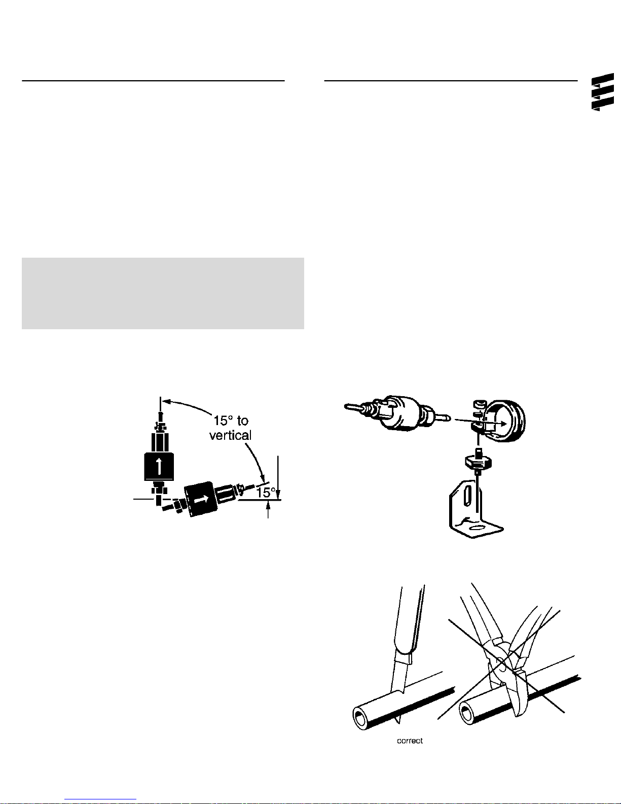
B) Fuel Metering Pump
If the pump needs to be mounted externally follow
these guidelines:
Choose a protected mounting location close to
the fuel pick-up pipe and heater.
Using the bracketand rubber mount provided,
install pump as shown in Figure II D.
Note: Proper mounting angle of the pump is
necessary to allow any air or vapor in the
fuel lines to pass through the pump rather
than cause a blockage.
Fuel Metering Pump Installation
Figure II D:
C) Fuel Line
- Route fuel lines from the fuel pick-up pipe to the
fuel metering pump then to the heater.
- Use fuel lines provided.
- Other sizes or types of fuel lines may inhibi
proper fuel flow.
- Make proper butt joints using clamps and
connector pieces as shown in Figure II E.
- Use a sharp utility knife to cut plastic fuel lines
to avoid burrs.
11
Figure II E
Page 13
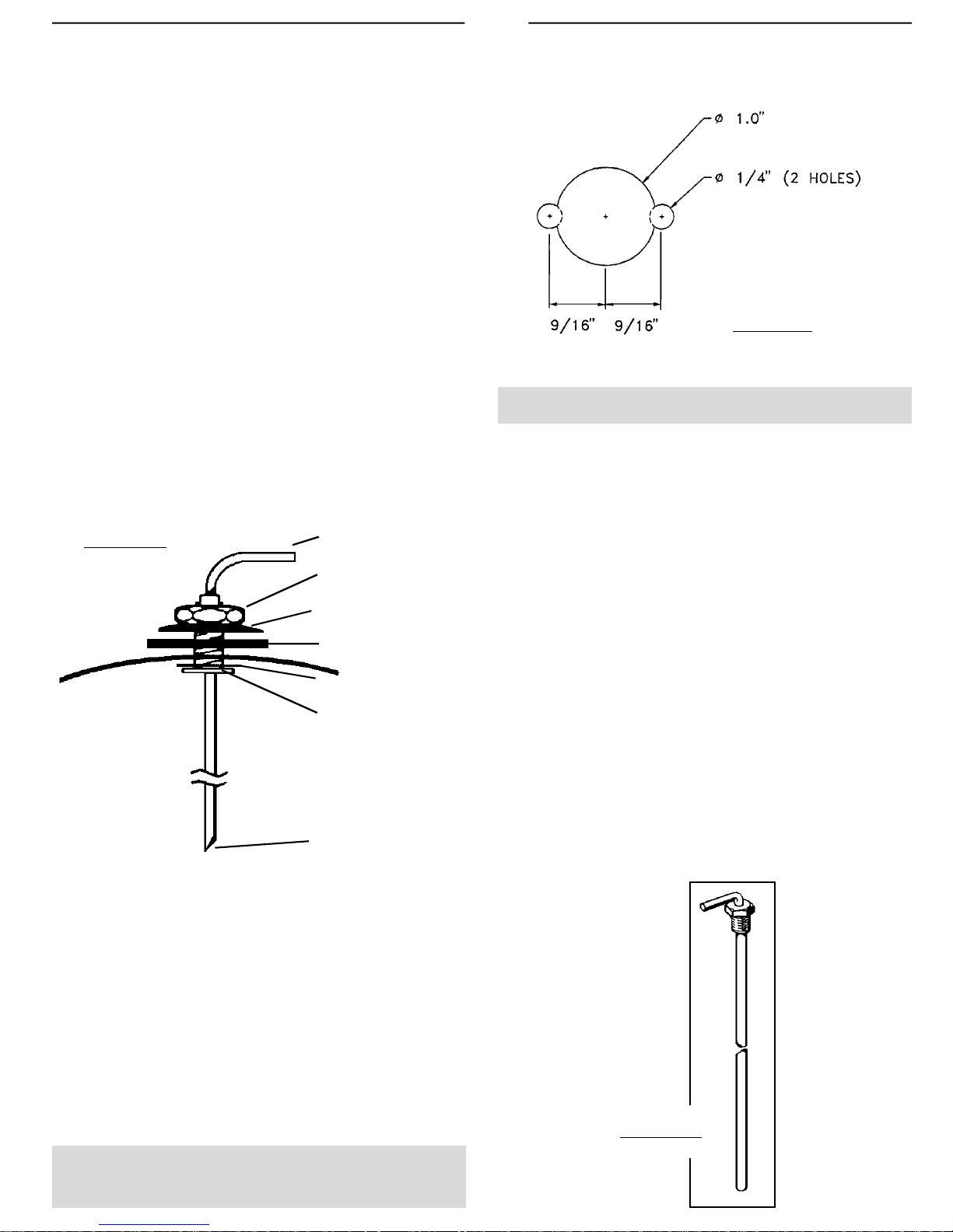
D) Fuel Pick-Up Pipe Installation
(Standard Pick-Up)
- Choose a protected mounting location close to
the pump and heater. A spare fuel sender
gauge plate provides an ideal mounting
location.
- Drill the mounting holes as shown in Figure II F.
- Cut the fuel pick-up pipe to length.
- Mount the fuel pick-up pipe as shown in
FigureIIG.
12
- Lower the fuel pick-up pipe (with reinforcing
washer) into the tank using the slot created by
the two 1/4” holes.
- Lift the assembly into position through the 1”
hole.
- Assemble the rubber washer, metal cup washer
and nut.
Figure II G
Fuel Pick-Up Pipe
Nut
Sheet Metal Washer
Rubber Gasket
Steel Safety Washer
Holding Tabs
Allow 4” from fuel pick-up
to tank bottom. Allow
only 1” for flat bottom
tanks.
Figure II F
Note: Drill the two 1/4” holes first.
( Optional Pick-Up Pipe with NPT fitting )
- Remove an existing plug from the top of the
fuel tank.
- Cut the fuel pick-up pipe to length.
- Secure the fuel pick-up pipe into position using
the combined NPT compression fitting as
shown in Figure II H.
Note: NPT fittings are available in various
sizes (Refer to parts section).
End tip of the fuel pick-up
pipe should have angle
so as to avoid picking up
dirt and subsequent
blockage
Figure II H
Page 14
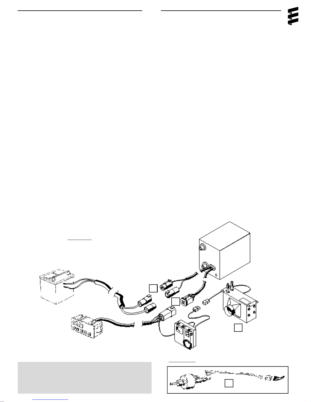
5. Electrical Connections
13
Caution: To avoid potential short circuit
damage during installation, Make
connection to the positive terminal at
battery after all electrical connections
are complete.
A) Power Harness....................................................
B) Switch Harness.....................................................
C) Fuel Metering Pump Harness...............................
All harnesses should connect to mating plugs atthe
heater box.
- 2 core harness (red and brown).
- Connect red wire to vehicle battery (+), use ring
terminal provided.
- Connect brown wire to vehicle battery (-), use ring
terminal provided.
- 5 core harness [(red, brown, yellow, blue)
black-optional, for bunk fan power supply]
- Fuel Metering Pump Harness is pre-connected
when box is provided with pump pre-mounted.
- If mounted externally, connect wires to fuel
metering pump using single terminals and rubber
protective boots provided with the heater- no
polarity required ).
- 2 core harness (green, green).
- Connect fuel metering pump harness using two
single connectors. Figure IIa.
D) Bunk Heat Exchanger (optional).......................
Figure II I
- single black wire from switch connector.
- connect as described in Heat Exchanger
plumbing section. (pg.8)
A
B
D
Note: All harnesses should be cut to length.
All exposed electrical connections should
be coated with protective grease.
Figure II Ia
C
Page 15
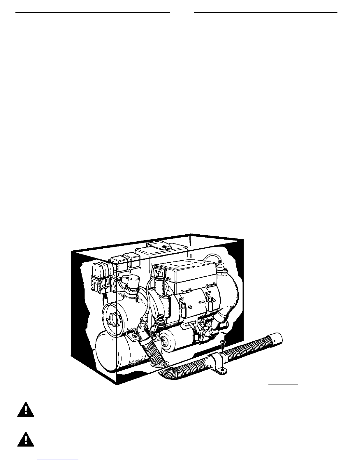
6 Exhaust Connection
A 30mm flexible stainless steel exhaust pipe (1
meter long), exhaust clamps and holders are
provided with the heater kit. Connect the
exhaust as follows:
Caution: Run exhaust so that it cannot be
plugged by dirt, water or snow.
Ensure the outlet does not face into
the vehicle slip stream.
Install exhaust pipe with a slight
slope or drill 5mm holes in lowest
point to allow water to run off.
Any restriction in exhaust will cause
operational problems.
Feed the exhaust pipe through the silicone
(white) gasket on the bottom of the box. Run to
an open area to the rear or side of the vehicle so
that fumes can not build up and enter the cab or
the heater box.
Secure the exhaust pipe internally at the heater
and externally using clamps and holders provided. Figure II J.
14
Warning: The exhaust is hot, keep a
minimum of 2” clearance from any heat
sensitive material
Warning: Route exhaust so that the
exhaust fumes cannot enter the passenger compartment.
Figure II J
Page 16
7. Operating Switches
A Push/Pull Switch is supplied with the heater, an
optional 99 Hour Digital Timer or a 7 Day Timer are
also available. Connect the operating switch as follows.
A. Push/Pull Switch
- Mount switch in a location where it is easily
accessible.
- Mount using hardware supplied.
- Connect the 25’ switch harness to the
connector at the heater and run the harness to
the switch location.
- Cut harness to length at the switch and install
terminals.
- Connect wiring as shown in Figure II K.
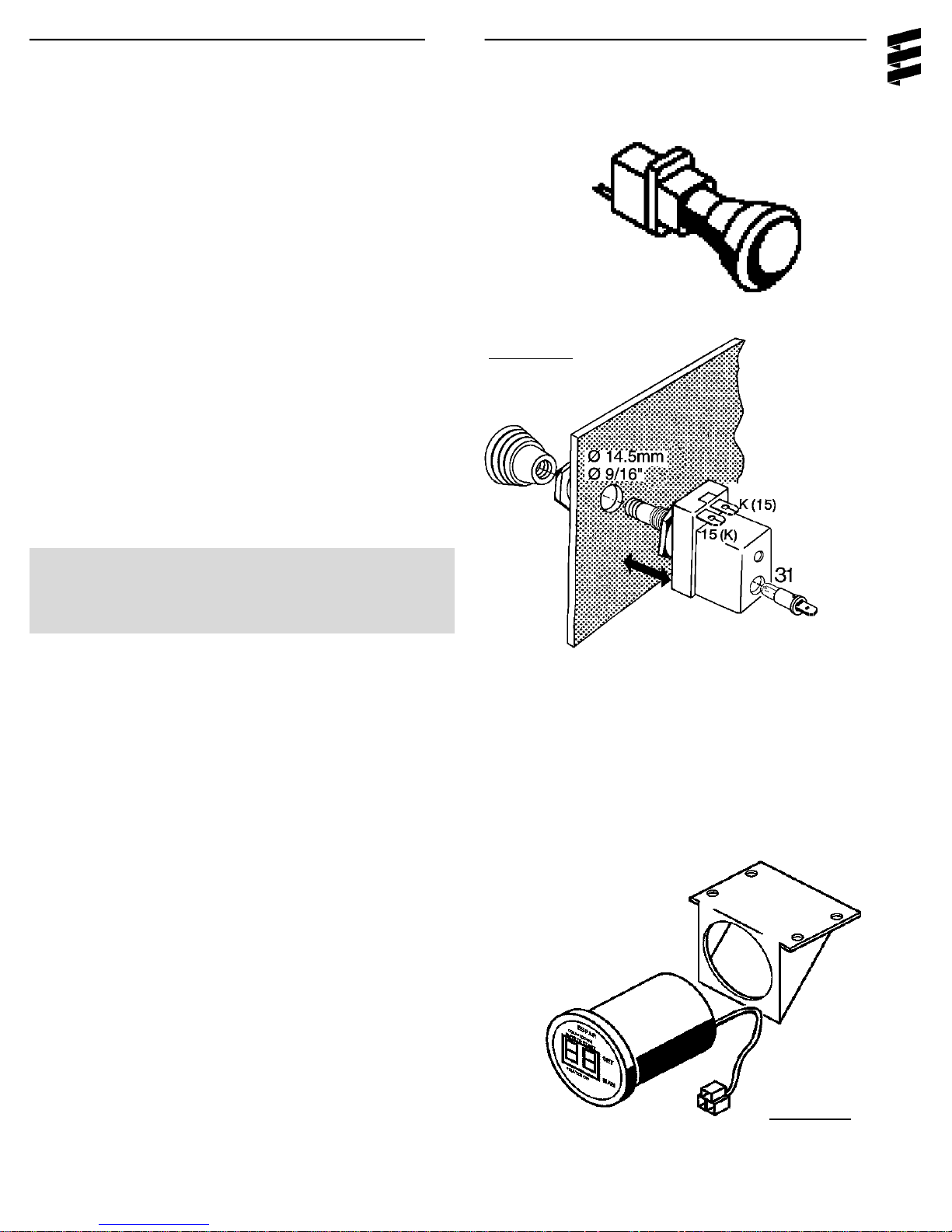
15
Figure II K
Control Wiring
Push/Pull Switch
Brown - 31
Red - K (15)
Yellow - 15 (K)
Note Wired as above the switch light glows
when pulled out and is off when
pushed in.
B. 99 Hour Digital Timer
This timer is pre-set by Espar to operate the heater
for one (1) hour only. If an alternative run time setting is desired refer to the instructions provided with
the timer.
- Mount the timer using a 2” hole in the dash or
the optional mounting bracket.
- Mount timer using hardware supplied.
- Connect the 25’ switch harness to the
connector at the heater and run the harness to
the switch location.
- Cut harness to length and terminate wires.
- Attach using connector provided.
Red-Red
Yellow-Yellow
Brown-Brown
Figure II L
Page 17
C. 7 DayTimer
The 7 day timer is capable of setting up to 3 preset
start times within 24 hrs. or 1 start time with in 7
days. It also has other functions such as a current
time display and a heater numeric fault code. Refer
to instructions provided with timer for setting
options.
- Mount timer and bracket in a suitable location.
- Connect the 25’ switch harness to the
connector at the heater and run the harness to
the switch location.
- Cut harness to length at the switch and install
terminals.
- Connect switch harness to timer..Figure II M
- Refer to timer instructions for other wiring
options.
16
Figure II M
8. Optional Thermostat for Bunk Heat Exchanger
This thermostat is used to control the fan motor of
the heat exchanger (OEM or optional Espar Heat
Exchanger) inside the truck’s sleeper, thereby
allowing for interior cab heating.
- Mount the thermostat in a location where it is
easily accessible and it’s temperature sensor is
representative of the area being heated.
- Mount using the mounting slots in it’s base.
- Connect wiring as shown on page 8
Figure II N
Page 18

17
III Heater Operation
1. Pre-Start Procedures
Upon completion of installation prepare the heater
as follows:
- Check all fuel, electrical and plumbing
connections.
- Refill the engine coolant
- Bleed air from the coolant system by loosening
the top heater hose to allow air to escape.
Resecure the heater hose.
- Run engine to further bleed the system.
- Top up engine coolant.
2. Start Up
Once switched on the following sequence occurs:
3. Running
Once ignition is successful the following
operations take place:
- Heater runs in full heat mode.
- Once coolant reaches 194°F (90°C) the
heater automatically switches to low heat mode
and continues to run.
- If coolant temperature drops to 176°F (80°C) the
heater will automatically switch back to full
heat mode.
- If coolant temperature continues to rise, the
heater will automatically switch off once coolant
temperature reaches 201°F (94°C).
- The water pump will continue to circulate
coolant to allow the heater to monitor engine
temperature.
- The heater will automatically re-start once
coolant temperature reaches 176°F (80°C).
- Combustion air blower starts.
- Water pump starts.
- Control unit checks all functions.
- Glow plug begins to preheat combustion
chamber.
- Control unit checks input voltage (under or over
voltage will cause heater to shut down).
- After the 20-50 second combustion chamber
preheat the fuel pump will start.
- Once ignition takes place the flame sensor will
automatically switch the glow plug off
(ignition time: 1-3 minutes maximum).
Note: If the heater fails to start the first time it will
automatically attempt a second start. If
unsuccessful the heater will shut down
completely.
Note: On initial start up the heater may require
several start attempts to self prime the fuel
system
- The heater will continue to run as described
above until it is switched OFF, either manually,
automatically by a timer or heater malfunction
shutdown.
Note: While in running mode if the heater should
shut down due to flame out, it wil
automatically attempt one restart, if
successful it will continue to run, if not it
shuts down completely.
Note: During operation the heater continually
senses the input voltage from the batteries,
if the input voltage drops to approximately
10.0 volts (20.0 V for a 24 V system) the
heater will automatically shut down.
4. Switching Off
When the heater is switched off, manually or automatically, it starts a controlled cool down cycle.
- The fuel metering pump stops delivering fuel
and the flame is extinguished.
- The glow plug is re-energized for a 15 second
after glow.
- The combustion air blower and water pump
continue to run for a three (3) minute cool down
cycle, then switch OFF.
Page 19

Warning: The heater must be
switched OFF while any fuel
tank on the vehicle is being
filled.
Warning: The heater MUST NOT be
operated in garages or
enclosed areas.
5. Safety Equipment
The control unit, overheat switch and flame sensor
continually monitor heater functions and will shut
down the heater in case of a malfunction.
- The control unit ensures electrical circuits (glow
plug, fuel metering pump, combustion air blower
etc.) are complete prior to starting the heater.
18
- If the heater fails to ignite within 90 seconds of
the fuel pump being started, the starting proce
dure will be repeated. If the heater again fails to
ignite after 90 seconds of fuel being pumped, a
“no” start safety shutdown” follows.
- If the heater flames out during operation, the
heater automatically attempts to restart. If the
heater fails to ignite within 90 seconds of fuel
delivery, or ignites but flames out again within 3
minutes, “flame out” shutdown follows.
- Overheating due to lack of water, a restriction
or a poorly bled coolant system results in the
safety cutout switch tripping. Fuel delivery will
cease and an “overheat shut down” follows.
- If at any time the voltage drops below 10.0v or
20.0v (for 24V), or rises above 14.0v or 28.0v
(for 24V), “high/low voltage” shutdown follows
(after a 20 second delay).
Page 20

6. Operational Flow Chart
19
Page 21

Page 22

IV. Maintenance Troubleshooting and Repairs
1. Recommended Periodic Maintenance
- Remove the glow plug and inspect for carbon
build up. Clean or replace.
- Remove the glow plug screen and inspect for
carbon build up. Clean or replace. If cleaning is
required, use brass brush (Espar part number
CA0 05 003).
- Make sure vent hole is open. Espa
recommends the use of non detergent 100%
volatile carburetor cleaner and an air gun will also
help. Remove loose carbon from the glow plug
chamber.
- Check coolant hoses, clamps, and make sure all
valves are open. Maintain the engine
manufacturers recommended coolant level and
ensure that the heater is properly bled after
service on or involving the coolant system.
21
- Run your heater at least once a month during the
year (for a minimum of 15 minutes).
- Maintain your batteries and all electrical
connections in good condition. With insufficient
power the heater will not start. Low and high
voltage cutouts will shut the heater down
automatically.
- Use fuel suitable for the climate (see engine
manufacturers recommendations). Blending used
engine oil with diesel fuel is not permitted.
2. Troubleshooting
A. Basic Troubleshooting
In the event of failure there are several items which
should be checked first before any major
roubleshooting is done.
Check
- Circuit breakers and Fuses.
- For breaks on Glow Plug coil.
- Electrical lines and connections
- For interference in Combustion air and Exhaust
pipes.
- That there is fuel in the tank.
- Has the overheat switch triggered? Figure IV A
Figure IV A
Press the raised knob of the rubber cover to reset
the overheat switch located below.
If a fault can’t be detected follow one of the other
troubleshooting methods outlined in this manual
Page 23

22
B. Manual Troubleshooting
To manually troubleshoot the heater match the fault with the cause and prescribed remedy.
Fault Cause Remedy
Heater runs 5 seconds Glow plug defective.......................................... Replace glow plug.
at start then shuts off. Electric motor defective or blower blocked....... Replace blower.
Harness to fuel metering pump not connected. Check line.
Overheat switch tripped.................................... Reset overheat switch.
Insufficient coolant...................................... Top up coolant.
Coolant circuit not properly bled................. Bleed coolant circuit.
Coolant pump defective.............................. Replace coolant pump, reset safety thermal
switch.
Short circuit in the flame sensor...................... Replace flame sensor.
Heater runs for 30 Under voltage.................................................... Check/Charge battery.
seconds at start then Overvoltage...................................................... Check vehicle charging system.
shuts off. Corrosion on electrical connections................. Clean electrical connections.
Flame goes out in Insufficient fuel................................................. Measure fuel quantity.
low mode. Speed of blower not reduced from high Replace partial load resistor .
to low. Replace control unit.
Replace change over relay
Flame goes out in Insufficient fuel................................................. Measure fuel quantity.
high mode Vapor lock in fuel line....................................... Fuel gets too hot, change position of fuel lines
Flame sensor defective.................................... Replace flame sensor.
Non-start. Fuel line not filled............................................. Restart, check fuel line.
Safety time (90 sec.) Insufficient fuel................................................. Measure fuel quantity.
exceeded and Defective glow plug.......................................... Replace glow plug.
automatic cutout. No fuel.............................................................. Fill tank
Metering pump seizure.................................... Replace metering pump.
Short circuit at metering pump......................... Check pump.
No pulse at metering pump.............................. Replace control unit.
Automatic cut-out after Flame sensor leads reversed........................... Check connection against wiring diagram.
3-5 minutes. Flame sensor interruption................................ Replace flame sensor.
Insufficient fuel................................................. Measure fuel quantity.
Delayed start Heater in cool down mode................................ Wait for delayed shut-off.
Water temperature still above the triggering Wait until temperature falls below triggering
point for the temperature sensor [approx. point.
176°F (80°C)].
Temperature sensor interruption...................... Replace temperature sensor.
Page 24

C. Self Diagnostics Troubleshooting
The D7WBoxed heater is equipped with an auto-
matic testing capability which can be used to check
for faults. A built-in LED provides a full time diag nostics display. The Optional 7 Day timer provides
a numeric fault code display.Both are covered on
the following pages.
1. Built-in LED and Diagnostic display.
The indicator and fault code chart are located within the box (Figures IV B). Definitions to the codes
are found on the next few pages.
23
LED
Figures IV B
DIAGNOSTIC SIGNALS
FALSE FLAME RECOGNITION
FLAME OUT IN LOW SETTING
FLAME OUT IN HIGH SETTING
GLOW PLUG
BURNER MOTOR DOES NOT TURN
UNDER VOLTAGE
OVERVOLTAGE
NO START SAFETY TIME EXCEEDED
GLOW PLUG RELAY
TEMPERATURE SENSOR
SHORT CIRCUIT, FUEL METERING PUMP
FLAME SENSOR
EXTERNAL ELECTRICAL INTERFERENCE
CONTROL UNIT
OVERHEATING
NORMAL OPERATION
WARNING VOLTAGE - UNDER/OVER
0.3 SECONDS
1.6 SECONDS
Page 25

24
Page 26

25
Page 27

26
Page 28

D. 7 Day Timer Troubleshooting
The 7 day timer (Figure IV C) has a fault code
retrieval device built into the unit. This function
automatically activates if the heater is experiencing problems.
- Fault codes appear on the LCD display screen.
- These codes can then be translated from the
charts on the previous pages.
E. Circuit Tester Troubleshooting
The purpose of this tester is to help a service
technician troubleshoot problems faster and more
accurately. It tests individual electrical components, checks the continuity of each circuit and
runs the heater manually.
27
Figure IV C
Note: To use this tester (P/N CA1 05 010) with
the D7W 25 1807 you will require an
adapter-P/N CA1 05 023
1. Initial Set Up
- All switches should be in the “Off ” position.
- Plug in the connectors from the tester to the
corresponding ones on the heater harness.
- Ensure proper power, fuel and coolant
connections.
2. Operating Instructions
- Switch the power switch to the “On” position and
the voltmeter will indicate the voltage across
the control unit. The voltage must be between
10.0V and 14.0V, on a 12V system or between
20V and 28V on a 24V system.
- Set the heater switch or timer to run position.
- The red “Switch On” LED should illuminate.
Figures IV D
- Test individual components by switching each of
the nine switches on the right side of the tester
to “CHECK” position.
- The ohmmeter will indicate the resistance value
of each component as high or low.
- Compare measured value to componen
resistance chart in Table 1.
- If any mismatch is indicated the component
should be replaced.
- Do not measure more than one component at a
time.
Page 29

Table 1 - Components Resistance Chart
Component Resistance
Combustion Air Blower Low
Water Pump Low
Glow Plug Low
Overheat Switch Low
Fuel Metering Pump Low
Temperature Sensor Medium
Flame Sensor High when exchanger is cool
Partial Load Resistor Low
Heat Exchanger Relay Low
3. To Manually Run Heater
28
Low when exchanger is warm
Start Up:
- Switch combustion air blower switch to “High”
position.
- Combustion motor will run at high speed.
- Switch water pump switch to “On” position.
- Water pump circulates coolant through the
system.
- Switch glow plug to “On” position and wait for
30 seconds.
- Glow plug begins preheating.
Note: Combustion air blower motor speed will
decrease due to voltage drop.
- Switch fuel metering pump switch to
“High” position.
- Fuel metering pump delivers fuel to combustion
chamber and establishes a flame.
Low Heat: Switch combustion air blower motor
switch to “Low” position.
Switch fuel metering pump switch to
“Low” position.
Note: The heater is now running in low heat mode.
Cool Down: Switch fuel metering pump switch to
“Off” position.
Switch the combustion air blower motor
switch to “High” position.
Wait for 3 minutes for the heater to cool
down.
Switch combustion air blower motor
switch to “Off” position.
Switch water pump switch to “Off”
position.
Note: The heater is now off. Turn the power switch
off and disconnect tester.
Note: If the fuel metering pump does not receive
the electric pulses then the overheat switch
may be tripped. Reset the overheat switch.
Check the fuse in tester - if blown
replace with AGC-1.
High Heat: Once a flame is established
(combustion is heard) wait 30 seconds
then switch the glow plug off. The
heater is now running in high
heat mode.
Note: Combustion air blower motor speed and
fuel metering pump pulse frequency will
increase due to voltage increase.
Page 30

3. Fuel Quantity Test
The fuel Quantity should be tested if the heater has
difficulty starting or maintaining a flame.
29
B). Measurement
- Switch on the heater.
Note: Measure the fuel quantity when the batter y
is sufficiently charged. At least 11/22V and
at most 13/26V should be applied at the
control unit during measurement.
A). Preparation
- Detach the fuel line from the heater.
- Insert the fuel line into a measuring glass.
- Connect a voltmeter to terminals A13 (+) and A12
(-) of the control unit.
[C6 (+) and A4 (-) on models 25 1666/1667].
- Disconnect the glow plug leads from the glow plug
and connect a test light across the two leads.
- Switch the heater on and allow the fuel line to
bleed.(approx.25-55 seconds)
- Switch off the heater and empty the measuring
glass.
- Hold the fuel line in the measuring glass while fuel
is being delivered.
- Fuel starts being pumped 25 - 55 seconds after
switch-on.
- Hold the measuring glass at the level of the plug
during measurement.
- Read the voltage at the voltmeter.
- The pump will stop delivering fuel automatically
after 90 seconds.
- Switch off the heater.
C. Evaluation
- Read the fuel quantity in the measuring glass.
- Transpose the readings into the appropriate
diagram. Figures IV F
- The fuel consumption is OK if the intersection of
the two readings are within the limit curves.
- If the intersection is outside the limit curves, inspect
the fuel system and replace fuel metering pump if
necessary.
Figure IV E
Connect Test Lamp
Positive line to
voltmeter
Note: Do not adjust fuel metering pump.
Adjustments will only provide a tempora ry fix.
Control Unit
Negative line to voltmeter
Positive line
to voltmeter
Voltmeter
Negative line
to voltmeter
Continued on next page.....
New
Model 25 1807
Model 25 1666, 1667 1673
Connection of voltmeter to control unit
Old
Page 31

30
Figures IV F
Page 32

31
4. Repair Steps
1. Glow Plug Removal, Inspection and Replacement
2. Glow Plug Screen Removal, Inspection and Replacement
3. Series Resistor Removal
4. Cover Removal
5. 12-pin Plug Removal
6. Temperature Sensor Replacement
7. Flame Sensor Replacement
8. Overheat Switch Removal
9. Partial-Load Resistor Removal
10 Water Pump Replacement
11. Combustion Air Blower Removal
12. Flame Tube Removal
13. Heat Exchanger Removal, Inspection and Replacement
14. Cover and Bracket Removal
1. Glow Plug Removal,
Inspection and Replacement
- Take off the plug cap
- Loosen the hex nut and detach the plug cable
- Unscrew the glow plug
- Inspect glow plug and coil for carbon build up
breaks or metal fatigue
- Clean or replace if necessary
- Re-install in reverse order
2. Glow Screen Removal,
Inspection and Replacement
- Remove the glow plug
- Remove screen and clean using varsol,
brass wire brush and compressed air
- Replace if necessary
- Clean glow plug chamber to remove
carbon build up
- Re-install screen
Figure IV G
Figure IV H
continued....
Page 33

When replacing the glow plug screen,
be sure to insert it in the manner shown
in Figure IV I
32
Figure IV I
3. Series Resistor Removal
(24 volt only)
- Remove the cap from the series resistor
- Loosen the hex nut
- Detach the cable
- Unscrew the series resistor
4. Cover Removal
- Unclip the cover from the holder
using a screwdriver
Figure IV J
Figure IV K
Note when re-installing:
- The cover cap must be fitted
splash-water tight, ensure that
all grommets are properly positioned
Page 34

5. 12 pin Plug Removal
- Remove the cover
- Unclip the plug from the
holder using a screwdriver
- Dismantle the plug
33
Figures IV M
Water pump (Brown)
Combustion air blower
change relay (Black/Red)
Temperature sensor (Brown)
Temperature sensor (Grey)
Flame sensor (Grey)
Flame sensor (Grey)
Speed change relay (Black)
Combustion air blower
Water pump (Black)
D7WBoxed
Model 25 1807
speed
Overheat switch (White)
Overheat switch (White)
(Brown)
Water pump (Brown)
Combustion air blower
Partial load resistor (Red)
Temperature sensor (Brown)
Temperature sensor(Grey)
Flame sensor (Grey)
Flame sensor (Brown)
Partial load resistor (Red)
Combustion air blower
Water pump (Black)
Model 20 1673
25 1666
25 1667
Figure IV L
(Violet)
Overheat switch (White)
Overheat switch (White)
(Brown)
6. Temperature Sensor Replacement
- Before removing the sensor, reduce the
excess pressure in the cooling system
by opening the radiator filler cap
- To prevent the coolant from flowing out
pinch the water supply and return hoses shut
- Remove the cover
- Remove the 12 pin plug
- Remove pins 8 and10 from plug housing
(see Figure IV M).
- Unscrew the temperature sensor
- After reinstallation, bleed the water circuit
See repair procedure 15.
Figure IV
Page 35

7A. Flame Sensor Replacement
Model 25 1807
- Remove the cover
- Remove the 12 pin plug
- Remove pins 7 and 9 from plug housing
- (see Figure IV M)
- Unscrew the flame sensor from the heat exchanger
exhaust port
34
Figure IV O
7B. Flame Sensor Replacement
Model 20 1673
25 1666
25 1667
- Remove the cover
- Remove the 12 pin plug
- Remove pins 7 and 9 from plug housing
(see Figure IV M).
- Unclip the retaining spring
- Remove the flame sensor from the holder
8A. Overheat Switch Removal
Model 25 1807
- Before removing these, reduce the excess
pressure in the cooling system by opening the
radiator filler cap
- To prevent the coolant from flowing out pinch
the water supply and return hoses shut
- Remove the cover
- Remove the 12 pin plug
- Remove pins 11 and 12 from plug housing
(see Figure IV M).
- Unscrew the cross-recessed screws
- Remove the (spring-loaded) overheat switch
Figure IV P
Figure IV Q
Continued....
Page 36

Note when re-installing:
- Use new O ring and seal
- Lubricate prior to installing
- After installation, bleed the water circuit
35
8B. Overheat Switch Removal
Model 20 1673
25 1666
25 1667
- Before removing, reduce the excess
pressure in the cooling system by opening
the radiator filler cap
- To prevent the coolant from flowing out pinch
the water supply and return hoses shut.
- Remove the cover
- Remove the 12 pin plug.
- Remove pins 11 and 12 from plug housing
(see Figure IV M).
- Unscrew the overheat switch
Note when re-installing:
- Use new O ring and seal
- Lubricate prior to installing
- After installation, bleed the water circuit
Figure IV R
9. Partial-Load Resistor Removal
- Remove the cover
- Remove the 12 pin plug
- Remove pins 5 and 6 from plug housing
(see Figure IV M)
- Remove the retaining clips from the partial-load
resistor
- Remove the partial-load resistor
Figure IV S
Page 37

10. Water Pump Replacement
- Before removing the pump, reduce the excess
pressure in the cooling system by opening the
radiator filler cap.
- To prevent the coolant from flowing out pinch the
water supply and return hoses shut.
- Remove the cover.
- Remove the 12 pin plug.
- Remove pins 1 and 2 from plug housing
(see Figure IV M).
- Undo the fastening clip of the water pump.
- Remove the water pump.
Note when re-installing:
- Use new O ring
- Lubricate prior to installing
- After installation, bleed the water circuit
11. Combustion Air Blower Removal
36
Figure IV T
- Remove the cover.
- Remove the 12 pin plug.
- Remove pins 3 and 4 out of the plug housing
(see Figure 4 M).
- Loosen the fastening screw and remove the
combustion air blower.
Note when re-installing:
- Use new O-ring
- Lubricate before installing
12. Flame Tube Removal
- Before removing the flame tube, reduce the excess
pressure in the cooling system by opening the
radiator filler cap
- To prevent the coolant from flowing out pinch
the water supply and return hoses shut
- Remove the heater
- Remove the combustion air blower
- Remove the glow plug cable and - in the case of 24
volt heaters - also the cable from the series resistor
- Remove the flame sensor
- Undo the clamping clip and remove the burner
Figure IV U
Note when re-installing:
- Use new O ring
- Lubricate prior to installing
- After installation, bleed the water circuit
Figure IV V
Page 38

13. Heat Exchanger Removal
- Before removing the heat exchanger, reduce the
excess pressure in the cooling system
by opening the radiator filler cap
- To prevent the coolant from flowing out pinch the
water supply and return hoses shut
- Remove the heater
- Remove the flame tube
- Lift the safety over heat switch off the
heat exchanger
- Remove the temperature sensor.
- Lever the heat exchanger out of the water jacket
using screwdrivers
- Remove the heat exchanger from the water jacket
(Figure IV X)
Note when re-installing:
- Use new O ring
- Lubricate prior to installing
- After installation, bleed the water circuit
37
Figure IV W
Figure IV X
14. Cover and Bracket Removal
- Remove the cover
- Remove the 12 pin plug
- Detach the 2 pin plug
- Remove the partial-load resistor
- Remove all grommets
- Take the bracket off the jacket
Note when re-installing:
- The cover cap must be fitted so that it is
splash-water tight, ensure that all grommets
are properly positioned
Figure IV Y
Page 39

Universal Model Boxed Model
25 1807 25 1666 (12V)
25 1666 25 1667 (24V)
25 1667 Freightliner
1. Principal Dimensions (Universal Model 25 1807)
Page 40

2. General Specifications
D7W Universal Model 25 1666 05
25 1667 05
Heat Output (±10%)............................................. 24,000 BTU (7 Kw) -High
Current at 12v (±10%)........................................ 26.0 amps/hr - Start (1-2 minutes)
Current at 24v (±10%)........................................ 22.0 amps/hr - Start (1-2 minutes)
Fuel Consumption (±5%)........................................ High Low
39
6,000 BTU (1.75 Kw) -Low
7.5 amps/hr - Running High
4.2 amps/hr - Running Low
3.8 amps/hr - Running High
2.0 amps/hr - Running Low
Heat Heat
US Gal/hr 0.24 0.06
Litre/hr 0.90 0.22
Coolant Pump Flow (±10%)................................. 420 US Gal/hr
1600 Litre/hr
Coolant Temperature................................. 176° F to 201° F (80° C to 95° C)
Range (±5%)
Overheat Temperature ................................. 275°F (135°C)
Shutdown (±10%)
Operating Voltage Range................................. 10.5 to 14.0 vdc at 12vdc
21.0 to 28.0 vdc at 24 vdc
Note:The heater control box is equipped with a
low voltage cutout to prevent battery drain
and a high voltage cutout to protect the
heater’s electrical parts.
Page 41

3. Universal Models 25 1807, 25 1666, 25 1667,
25 1673
1. Heater Location and Mounting
- Locate heater in a protected area (eg. storage
compartment, step box, engine compartment).
- Situate heater below the normal coolant level of
the engine.
- Guard against excessive road spray.
- Keep coolant hoses, fuel lines and electrical
wiring as short as possible.
- Do not mount heater inside the vehicle passenger
area.
- Mount using saddle bracket provided (refer to
template pattern shown).
2. Heater Plumbing
40
- Refer to D7W Boxed plumbing section (pg. 7)
3. Fuel System
- Refer to D7W Boxed fuel system section (pg.9).
4. Electrical Connections
(Universal 25 1666/67 & Boxed 25 1666)
Power - 2 core harness (red & brown).
Harness - Red wire direct to vehicle battery (+)
in line fuse.
- Brown wire to battery ground.
Switch - 3 core harness (red, brown & yellow)
Harness Run to location of switch.
Fuel Pump - 2 core harness (green & green)
Harness - Run to location of fuel pump
5. Exhaust Connections
- A 24mm flexible stainless steel exhaust pipe
(50”long), exhaust clamp and holder are
provided with the kit.
- Secure pipe to heater exhaust outlet and run to
an open area to the side or rear of the vehicle
so that fumes cannot build up and enter the cab
or be sucked in by the heater combustion air
blower.
- Refer to safety warnings on pg.13 of D7W Boxed
version.
Page 42

4. Freightliner
Plumbing
41
Freightliner Plumbing Diagram
Wiring (pg.46)
Freightliner Fuel & Electrical Accessories Part #
Internal Harness (complete) 806 103 006
Packard Connectors:
Switch
- Female, 3 hole housing CA1 91 001
- Terminal seal CA1 91 003
- Lock CA1 91 004
- Terminals CA1 90 015
CA1 90 091
Thermostat
- Housing (female 1-hole) CA1 91 042
- Lock CA1 91 045
Power
- Male, 3 hole housing CA1 91 031
- Lock CA1 91 032
- Seal CA1 91 034
- Terminals CA1 90 062
Fuel connectors
- Hose barb CA0 12 008
- Adapter CA0 12 007
- Washer CA3 00 322
90° BulkheadCA0 11 037
Page 43

D7W Universal
Model 25 1807
42
Page 44

D7W Boxed
Model 25 1666 (12V)
25 1667 (24V)
43
Page 45

D7W Boxed with Espar Heat Exchanger
Model 25 1666 (12V)
44
Page 46

D7W Universal
Model 25 1666 (12V)
25 1667 (24V)
45
Page 47

D7W Boxed Freightliner
Model 25 1807
46
Page 48

47
Bunk Blower Wiring Adapter
Model 25 1666
Wiring Adapter Kit for Bunk Blower Controls
D7W Model 25 1666
Page 49

48
D7W Parts Diagram
Main Heater Components
Models 25 1807
25 1666/67
Page 50

D7W Boxed Parts
Models 25 1807/25 1666
49
Page 51

Universal Parts
Models 25 1807
25 1666
25 1667
25 1673
50
Page 52

D7W Parts & Accessories
51
Page 53

52
Ref.
No. Description Part Number
1 Combustion air blower 24 V 25 1667 99 15 00 •
12 V 20 1673 99 15 00 • •
12 V 25 1807 99 15 00 •
2 Flame tube 25 1667 19 00 00 •
20 1673 19 00 00 •
25 1666 19 00 00 •
25 1806 19 00 00 •
3 Water pump 12 V 20 1673 25 01 00 • • •
24 V 25 1667 25 01 00 •
4 Glow plug harness 25 1667 01 04 00 •
20 1673 01 04 00 • •
5 Temperature sensor 25 1670 01 05 00 • • •
25 1806 99 01 05 •
6 Flame sensor 20 1645 01 06 00 • • •
6a 25 1769 01 02 00 •
7 Partial-load resistor 12 V 20 1673 01 07 00 • •
24 V 25 1667 01 07 00 •
7a Cable section with partial-load resistor 25 1807 01 01 00 •
8 Resetable overheat switch 20 1677 41 00 00 • • •
8a 25 1806 99 40 00 •
9 Water jacket 20 1673 99 01 01 • • •
9a 25 1806 01 03 00 •
10 Heat exchanger 20 1673 01 00 01 • • • •
11 Base 25 1676 01 00 03 • • • •
12 Grommet 20 1645 01 00 05 • • • •
13 Grommet 20 1645 01 00 06 • • • •
14 Cover 20 1645 01 00 11 • • • •
15 Glow plug 25 1830 01 01 00 • • • •
15a Glow plug screen 25 1666 10 00 01 • • • •
16 Retaining spring 20 1673 01 00 08 • • •
17 Series resistor 25 1667 01 00 01 •
18 Clamp 90mm-110mm 10 2065 09 01 10 • • • •
19 Clamp 46mm - 70mm CA1 10 047 • • • •
20 Holding strap 209 31 074 • • • •
21 Snap ring 171 19 250 • • •
22 Self tapping screw(hardware) 109 10 022 • • •
22a 103 10 310 • • •
22b 109 00 042 •
Page 54

53
Ref.
No. Description Part Number
23 Clip 151 10 051 • • • •
24 Terminal holder 206 31 346 • • • •
25 Terminal holder cover 206 31 347 • • • •
26 O-ring 89x4 320 75 002 • • • •
27 O-ring 17x2.5 320 75 001 • • • •
28 O-ring 7x2 320 75 111 • • • •
29 Clamp for flame tube 152 00 155 • • • •
30 Fuel metering pump 12 V 20 1673 45 00 00 •
12 V 25 1666 45 00 00 • •
24 V 25 1667 45 00 00 •
31 Exhaust pipe w/cap 30mmx1.3M 25 1816 80 08 00 • • • •
32 Exhaust muffler 24mm 20 1690 80 02 00 • • •
30mm 25 1806 80 01 00 •
33 Control unit 12 V 25 1666 50 00 00 • •
34 Cable harness, universal 20 1673 80 07 00 • • •
35 Cable 20 1668 80 05 00 • • • •
36 Coolant hose 90° 20 1673 80 00 01 • • • •
37 Coolant hose 180° 20 1673 80 00 03 • • • •
38 Heater mounting bracket 20 1673 80 00 02 • • • •
39 Plastic fuel line 2mm 090 31 117 • • • •
40 Fuel hose 5mm 360 75 350 • • • •
41 Plastic fuel line 4mm 090 31 101 • • • •
42 Rubber mount 6mm 20 1185 00 00 01 • • • •
43 Rubber mount self tapping 20 1673 80 01 01 • • •
44 FMP angle bracket 20 1348 03 00 04 • • • •
45 Double angle bracket 90° 20 1533 88 00 07 • • • •
46 Sleeve 20 1668 80 01 01 • • • •
47 Clamp 20mm-32mm 10 2065 02 00 32 • • • •
48 Pipe clamp 41mm, FMP holder 152 10 040 • • • •
49 Flex. exhaust clamp 26mm 152 61 102 • • •
30-32mm 152 10 061 •
50 Pipe clamp 28mm 152 10 051 • • •
34mm 152 10 043 •
51 Pipe clamp 12mm 152 10 058 • • • •
52 Pipe clamp 10mm 152 00 147 • • • •
53 Hex nut M6 CA3 00 208 • • • •
54 Spring washer 6mm CA3 00 308 • • • •
24 V 25 1667 50 00 00 •
12 V 25 1732 50 00 04 •
25 1807 80 04 00 •
Page 55

54
Ref.
No. Description Part Number
55 Bolt M6x16 CA3 00 126 • • •
56 Hex nut M8 CA3 00 209 • • • •
57 Spring washer 8mm CA3 00 309 • • • •
58 Rubber mount 8mm 330 00 036 • • • •
59 Hex bolt 5/16”x1/2” CA3 00 102 •
60 Hex nut 5/16” CA3 00 203 •
61 Sheet-metal screw, B3.9x19 H • • • •
62 Sheet-metal screw, B6.3x13 CA3 00 402 • • • •
63 Sheet-metal screw, B4.8x19 H • • • •
64 Sheet-metal screw, B3.9x32 H • • • •
65 Connecting pipe 20mm 20 1534 88 00 01 • • • •
66 T-piece, 20x20x20mm 20 1673 80 11 00 • • •
67 Reducing piece, 20x18mm 20 1645 89 00 06 • • • •
68 Water thermostat 3x18mm 330 00 160 • • •
69 Current regulator block 203 31 000 • •
70 Relay block 203 00 085 • • • •
71 Hex nut 3mm CA3 00 215 •
71a Lock washer 3mm CA3 00 315 •
72 Bolt M3x30 CA3 00 115-001 •
73 Fuel hose 3.5mm 360 75 300 • • • •
74 Relay 12 V 203 00 065 • • •
24 V 203 00 066 •
74a Relay 12 V 203 00 093 •
75 Fuse holder, bottom 204 31 004 • • • •
76 Fuse holder, cover 204 31 005 • • • •
77 Fuse insert 10A CA1 07 006 • • • •
15A CA1 07 002 • • • •
25A 204 00 089 • • • •
78 Terminal fuse holder, AWG12 206 73 058 • • • •
79 Rubber boot 320 31 120 • • • •
80 Socket male 3 hole 206 31 303 • • •
81 Socket female 3 hole 206 31 012 • • •
82 Flat-pin terminal AWG 14-18 CA1 90 005 • • • •
83 Terminal AWG 14-18 CA1 90 003 • • • •
84 Ring Terminal AWG 10-12 CA1 90 014 • • • •
85 End cap 24mm 25 1482 80 00 01 • • •
30mm 25 1785 80 02 00 •
86 Flex.exhaust tube 24mm x 1.3 M 360 61 292 • • •
30mm x 1.3 M 360 61 300 •
87 Current regulator 12 V 25 1548 01 00 01 • •
87a Current regulator 12 V 203 00 082 •
Page 56

55
Ref.
No. Description Part Number
88 Cable section 20 1673 80 05 00 • •
89 Clamp 9mm 10 2063 00 90 98 • • • •
90 Clamp 11mm 10 2063 01 10 98 • • • •
92 Timer, 99 hour CA1 00 050 • • • •
without bracket CA1 00 051 • • • •
93 Timer, 7 day 12 V 22 1000 30 12 00 • • • •
24 V 22 1000 30 13 00 • • • •
94 Wide terminal CA1 90 013 • •
95 Coolant pump seal kit 20 1673 25 04 00 • • • •
96 Screw M6x20 H • • • •
97 Integrated fuel filter 20 1312 00 00 06 • • • •
98 Fuel hose nipple 20 1621 45 00 02 • • • •
99 Holder, control unit 25 1714 80 05 01 •
100 Holder 25 1806 01 00 02 •
101 Seal ring, glow plug 25 1830 01 01 01 • • • •
102 Seal, overheat switch 25 1806 01 00 03 •
103 Bracket, overheat switch 25 1806 01 00 02 •
104 Bracket, overheat switch 20 1673 01 00 10 • • •
105 Rubber ring for fuel metering pump 20 1449 00 10 01 • •
106 Fuel metering pump holder 25 1156 20 00 11 • •
107 Exhaust seal 25 1216 88 03 01 • •
108 Cable grommet, square CA0 00 042 •
109 Heavy duty shock mount kit, 8mm CA0 00 062 • •
110 Bolt M8x50 CA3 00128 • •
111 Washer fender 5/16” x1.25” OD CA3 00 305 • •
112 Shock mount 8mm 2 piece CA3 00 128 • •
113 Threaded washer M8 CA3 00 333 • •
114 Spring washer 8mm CA3 00 302 • •
115 Hex nut 8mm CA3 00 209 • •
116 Box, cover CA0 10 031 • •
117 Box, base CA0 10 067 • •
118 Molded hose CA0 11 023 • •
119 Spring loaded clamp CA1 10 046 • •
120 LED, panel mount kit CA1 00 096 •
121 Internal control harness complete (short harness) CA1 60 713 •
CA1 60 708 •
122 Push pull switch 12V CA1 00 003 • •
123 Fuel pick-up 4mm CA0 12 058 • • • •
124 Custom ring type fuel pick up pipe CA0 12 012 • • • •
124a Gasket CA0 10 040 • • • •
Page 57

56
Ref.
No. Description Part Number
125 Custom straight pick up pipe 16” length CA0 00 030 • • • •
24” length CA0 12 053 • • • •
125a Compression fittings 1/4” NPT CA0 12 044 • • • •
3/8” NPT CA0 00 031 • • • •
1/2” NPT CA0 12 005 • • • •
126 Power cable CA1 65 713 •
127 Switch cable CA1 70 713 •
128 Power and switch cable complete CA1 60 702 • •
129 Replacement coupling ring for power switch cable CA1 91 014-001 •
130 Bezel (7 Day timer) 25 1482 70 01 00 • • • •
131 Mounting bracket (7 Day timer) CA0 10 061 • • • •
132 Mounting bracket (99 hr timer) CA0 00 032 • • • •
133 Washer - bulkhead CA 00 311 • •
134 Bulkhead hose connector CA0 11 011 • •
135 End cap CA0 11 016 • •
136 90° Bulkhead hose connector CA0 11 037 • •
137 Cap for circuit breaker CA1 04 106 •
138 Circuit breaker 30 AMP with cap CA1 07 101 •
139 Cross frame mounting tray CA0 10 022 • •
140 Side frame mounting tray CA0 10 057 • •
141 Grommet for fuel line 20 1280 09 01 03 •
142 Switch connector female CA1 91 071 •
143 Lock for CA1 91 071 CA1 91 073 •
144 Switch connector male CA1 91 072 •
145 Socket AWG 18 for CA1 91 072 CA1 90 258 •
146 Socket AWG 14 for CA1 91 072 CA1 90 259 •
147 Pin AWG 18 for CA1 91 071 CA1 90 257 •
148 Seal plug for CA1 91 072 or CA1 91 071 CA1 91 063 •
149 Lock for CA1 91 072 CA1 91 074 •
150 Switch connector male CA1 91 072 •
151 Power socket AWG10 for CA1 91 062 CA1 90 262 •
152 Power connector male CA1 91 062 •
153 Power connector female CA1 91 061 •
154 Power pin AWG10 for CA1 91 061 CA1 90 261 •
155 Hex nut 5/16” CA3 00 203 •
156 Spring washer 8mm CA3 00 309 • • • •
157 Shock mount 5/16” - 1 piece CA0 00 040 •
158 Hex bolt M6x12 CA3 00 103 •
159 Hex nut M6 CA3 00 208 •
160 Washer 6mm CA3 00 308 •
161 Thermostat 301 00 135 • • • •
Page 58

3rd. Printing - December 1996
Printed in Canada
P/N: 610-104-1296
Espar Products, Inc.
6435 Kestrel Road
Mississauga, Ontario
Canada L5T 1Z8
17370 N. Laurel Park Drive
Suite 400E
Livonia, Michigan
United States
48152
Canada: 905-670-0960
800-668-5676
Fax: 905-670-0728
U.S.: 800-387-4800
A member of the Worldwide Eberspächer Group of Companies
 Loading...