

Page 1

Glass Thermovec
Installation and Maintenance Manual
Page 2

CONTENTS
1.Preface
2.Safety precautions
2.1 Mark Notes
2.2 Icon Notes
2.3 Warning
2.4 Attention
3 Specifications
3.1 Parameter list
3.2 Working condition
3.3 Overall dimensions
3.4 The working principle of units
3.5 Unit characteristics
4 Installation
4.1 Installation precautions
4.2 Installation note places
4.3 Install note schemes
4.4 Conduit connections
5 Usage
5.1 Function description of wire controller
5.2 Usage of wire controller
6 Maintenance and Overhaul
6.1 Maintenance
6.2 Common fault and the solving methods
7 Appendix
7.1 Net control diagram
7.2 PCB I/O port
7.3 Wire Connection
Page 3

1. Preface
Thank you for choosing Earth Save Products Limited’s Glass Thermovec. Please read this installation
and maintenance manual carefully before attempting to install, use or maintain your Thermovec.
Your Thermovec must be installed by a suitably qualified and experienced technician to ensure that
it is installed safely and correct and also to comply with warranty requirements. Likewise, in the
unlikely event of a repair being necessary, it should only be carried out by a qualified technician
using genuine spare parts supplied by Earth Save Products Limited. Your Thermovec must be
installed, used and maintained in accordance with these instructions to ensure safety and comply
with warranty requirements.
Once your Thermovec is installed, these instructions should be kept in a safe place for reference. A
replacement can be obtained from Earth Save Products Limited.
V1.0
1 of 16
Page 4
Safety Precautions
Symbol
Meaning
Caution
Compulsory
Prohibited
Installation
Installation must be carried out by a qualified technician due to risk of leakage,
electrical shock or fire.
The Thermovec must be correctly earthed due to risk of electrical shock and
installed to comply will all electrical regulations
Ensure that the wall on which the Thermovec is to be mounted is structurally
sound and can take the weight of the unit
The Thermovec must be connected to the power supply via a fused spur with a
correctly rated fuse
If you need your Thermovec moved, a qualified technician must be engaged to do
so
Using the Thermovec
Do not put fingers or any object into any opening in the Thermovec
If your Thermovec emits unusual odours or sounds, turn the unit off immediately
and seek advice from your installer or ESP Ltd
Switch off your Thermovec before cleaning the case or the filters
Switch off your Thermovec before carrying out any maintenance
Do not modify or change any of the internal devices without consulting ESP Ltd.
To ensure the safe operation of your Thermovec please note the following:
Symbols used:
General Precautions:
Some basic safety rules should be followed when using any product that uses electricity and water,
such as:
Do not touch the appliance with wet skin.
Turn off the unit before cleaning it.
Do not damage or modify the power supply cord.
Do not place anything on the Thermovec nor climb upon it.
Ensure that all packing materials are disposed of safely and/or recycled.
V1.0
2 of 16
Page 5
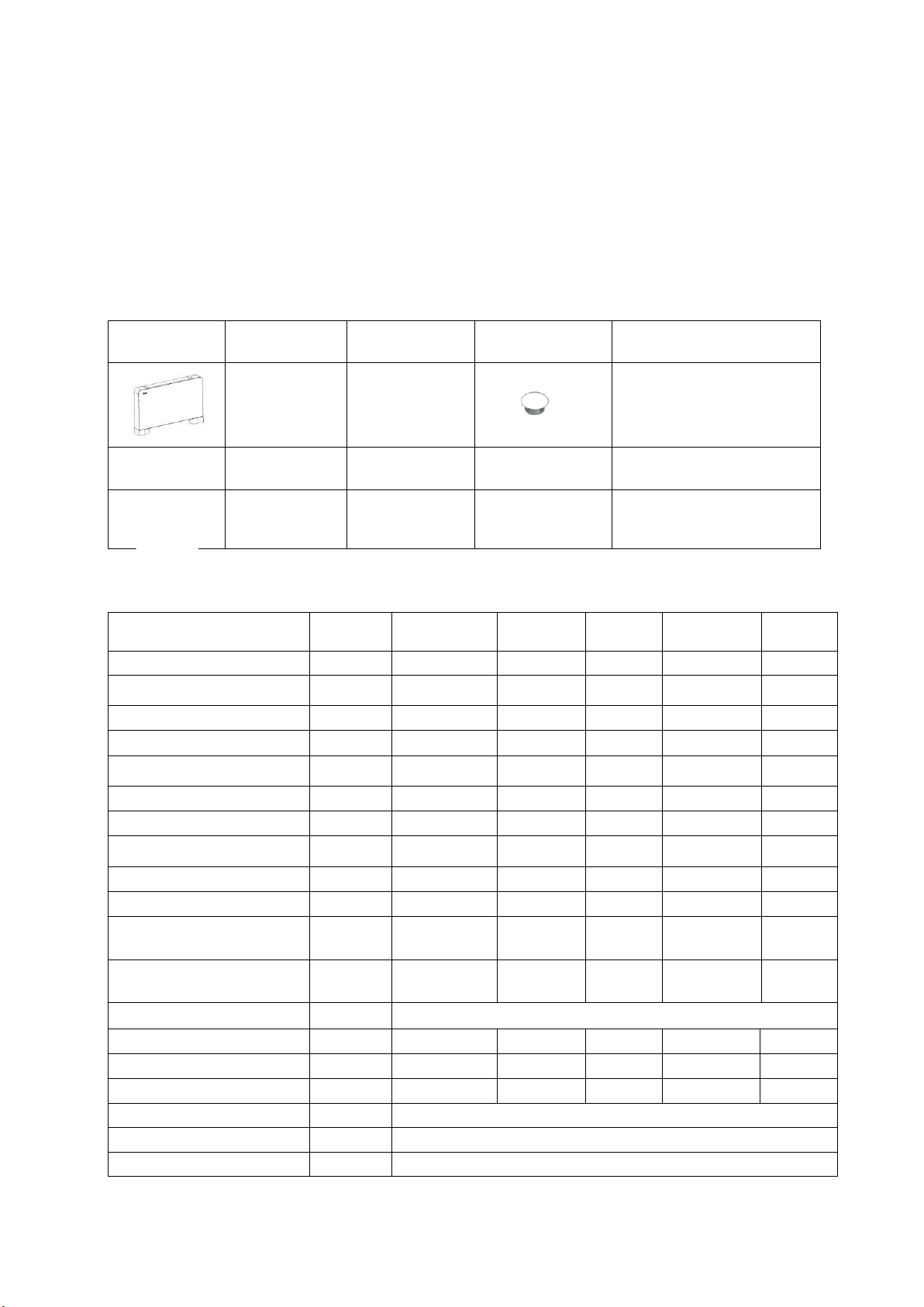
This appliance is not intended for use by persons (including children) with reduced physical,
Thermovec
Installation
Template
Manual
Screw Cap
Remote
X 2
Mounting
Brackets
Wall Plugs
Screws
Condensate
Drain Pipe
Feet
Unit Model
Units
ESP VFC
2.55G
ESP VFC
3.95G
ESP VFC
5.75G
ESP VFC
7.2G
ESP VFC
9.4G
Heating Capacity①
W
2550
3950
5750
7200
9400
Water flow rate①
m3/h
0.22
0.34
0.49
0.62
0.81
Pressure drop①
kPa
10.6
12.2
26.2
27.5
28.2
Heating capacity②
W
1350
2500
3350
4300
5200
Water flow rate②
m3/h
0.23
0.43
0.58
0.74
0.89
Pressure drop②
kPa
10.8
13.1
27.5
27.9
28.5
Cooling capacity③
W
1000
1900
2500
3500
4350
Water flow rate③
m3/h
0.17
0.33
0.43
0.60
0.75
Pressure drop③
kPa
11.1
13.3
27.7
28.3
30.6
Air volume
m3/h
160
320
460
580
650
Noise pressure at max air
flow
dB(A)
30
32
37
39
41
Noise pressure at min air
flow
dB(A)
24
27
28
28
30
Power Supply
V/Hz
220-240V~/50Hz
Power Input
W
15
20
23
25
32
Water In/Out tapping size
inch
3/4
3/4
3/4
3/4
3/4
Condensate Drain size
mm
16
16
16
16
16
Net Dimensions(L/W/H)
mm
See below
Shipping Dimensions(L/W/H)
mm
See package label
Net weight
kg
See nameplate
sensory or mental capabilities, or lack of experience and knowledge, unless they have been
given supervision or instruction concerning use of the appliance by a person responsible for
their safety.
Specifications.
Packing List.
Parameters
V1.0
3 of 16
Page 6
Gross weight
kg
See package label
Notes
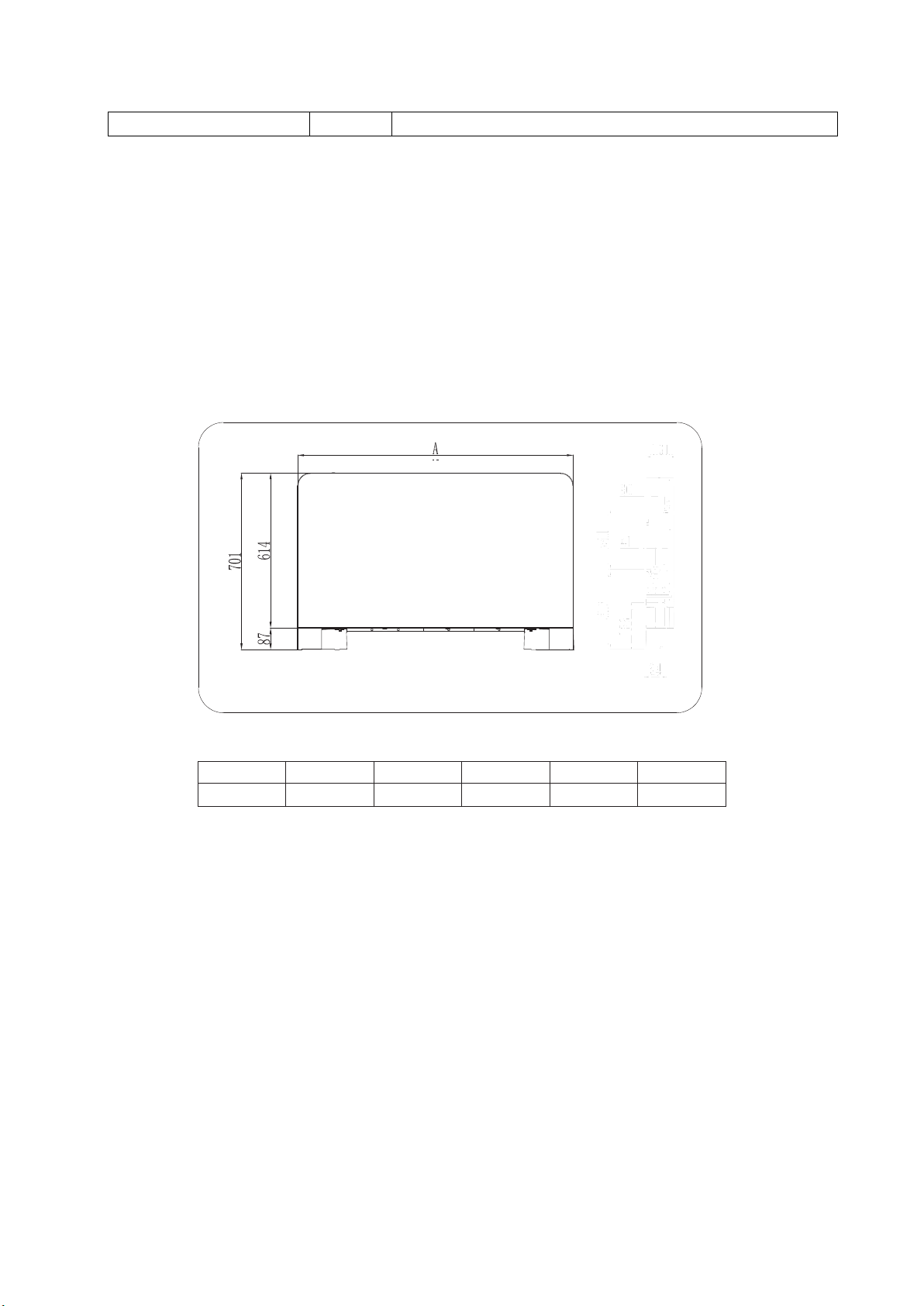
Unit Model
VFC2.55G
VFC 3.95G
VFC5.75G
VFC 7.2G
VFC 9. 4G
A
695
895
1095
1295
1495
1. Supply flow temperature of 70°C, return temperature of 60°C and 20°C ambient air temperature.
2. Supply flow temperature of 50°C, return temperature of 45°C and 20°C ambient air temperature.
3. Supply flow temperature of 7°C, return temperature of 13°C and 27°C ambient air temperature.
4.Noise level is measured in the standard anechoic chamber<17dB(A)
5. Above data is subject to change without prior notification.
Working conditions
Heating ambient temperature: 5-29℃, flow water temperature: 35-70℃.
Cooling ambient temperature: 9-35℃, return water temperature: 5-20℃.
Dimensions
3.3.1 Product model: VFC 2.55/3.95/5.75/7.2/9.4G
V1.0
4 of 16
Page 7

Heated or Cooled air is
distributed evenly
How it works
Ambient air is drawn in
Return
Flow
The Thermovec is supplied by hot or cold water from your ASHP. It draws air in from the room in
which it is installed, blows that air over a heat exchanger and exhausts the air into that room. The
temperature of the room is controlled by the Thermovec and the water flow is controlled by a
three-way valve. The air is distributed across the room in a much more efficient manner than a
traditional radiator.
Note: if the Thermovec is used for cooling, the condensate drain must be connected.
Unit characteristics:
Whisper Technology
The use of a cross-flow fan combined with wind-guiding technology make the
Thermovec quiet as a whisper.
Slimline
The Thermovec is only 130mm thick – thinner than traditional radiators of similar
output saving space.
Elegant Design
The rounded and clean outline ensures that the Thermovec will blend into any room.
Easy to use
With a simplified control menu, the Thermovec can be controlled via the touchscreen panel or the remote control. Note: if you are using a high-temperature
source, the Thermovec should be controlled with the remote control because the
glass whole unit can achieve a temperature of up to 70°C to the touch.
Installation
Installation precautions
To ensures that the installation is performed correctly and safely and to conform to the warranty
conditions the Thermovec must be installed by a suitably qualified technician and in accordance
with this manual.
The electrical aspects of the installation must be carried out in accordance with current regulations.
The Thermovec must be correctly earthed.
The unit must be installed in a position that allows routine maintenance such as cleaning the filter.
V1.0
5 of 16
Page 8

22mm
22mm
90mm
140 mm
400mm
Positioning the unit
Avoid installing the unit in proximity to other heat sources, in direct sunlight, in damp areas
or where it is likely to come into contact with water. Areas contaminated with combustible
fumes and high frequency radio signals should also be avoided.
Ensure that:
The wall on which the unit is to be installed is strong enough to support the weight.
You are not going to drill through wires, pipes or anything else important when
securing the brackets.
The mounting wall is perfectly flat.
There is nothing to interfere with the airflow around the Thermovec (see below).
If using the Thermovec for cooling, the condensate drain can be routed
satisfactorily.
Minimum Clearances:
Installation
Side opening
Lift the screw cap (A) and undo the screw (B) beneath it. Move the side panel (c) slightly and lift it
out.
6 of 16
V1.0
Page 9

First, lay the unit down
carefully to protect both
the Thermovec and the
surface on which it is
placed. Line up both
feet with the four screw
holes for each foot.
Next, using the 8
screws provided
attach the feet
securely, taking care
not to over tighten
the screws.
Mounting the Thermovec
Using the paper template, trace the position of the bracket holes.
Thermovec Feet.
If you are going to use the Thermovec feet, they must be attached before installation as shown in
the following two diagrams.
V1.0
7 of 16
Page 10

Fix the two brackets to the wall using suitable fixings: the supplied wall plugs are only suitable for
Flow
Return
The distribution pipework should be hot
flushed and pressure tested before the
Thermovec is connected. The distribution
pipework should be designed to reduce
resistance and automatic air bleed valve
incorporated at key points. The flow and
return should then be connected to the 3way valve as shown (Thermovec shown
from the back of the unit)
If the Thermovec is to be used for cooling, a
condensate drain pipe must be fitted to take
resulting condensate away from the unit and
dispose of it safely. The condensate will drip from
aperture A, collect in tray B and the pipe should be
connected at C. If the pipe is to be connected to a
drain, a waterless trap should be used.
certain types of walls. Do not tighten until final adjustment to ‘level’ has been made and checked.
4.Installation
Connecting the Pipework.
V1.0
8 of 16
Page 11

Bleeding the Thermovec
Power on/off. Also used to cancel an action or to return to the previous menu
Air Vent or Time. Used to display time settings, set the timer and to turn the air vent on
or off.
Fan Speed. Used to set the fan speed.
Up. Used to increase a value or to go up a menu level.
Down. Used to decrease a value or to go down a menu level.
The Thermovec must be bled before power is
applied i.e. before it is switched on. Use a
screwdriver to open the bleed valve on the
side of the Thermovec until all air is expelled
from the unit then close the valve again taking
care not to over-tighten it. It is
recommended that each Thermovec be bled
again one it has been running for a few hours.
If the unit is powered-up before it is bled, the
3-way valve will have closed and it must be
opened manually.
Using the Thermovec
The Control Panel – what the symbol mean
V1.0
9 of 16
Page 12

Mode. Used to toggle between modes.
Pressing the on/off button
for 0.5Secs will power the
unit on/off.
Press to
toggle between
modes.
Press to
toggle between
modes
In Auto, Heating or Cooling modes,
the target temperature will show for
5 secs after the mode is selected.
The display will then revert to
ambient temp.
In Dehumidifying and Ventilation
modes, the display will only show the
ambient temperature.
Changing the Target Temperature
To Change the target temperature, simply press the up or down buttons once, then use the up
or down buttons to select the required temperature. Once you have done so, the display will
return to the default display and save the target temperature after 5 Secs:
Note: If no button has been pressed for 1 min, the control panel will be hidden. Simply touch the
control panel area to display the controls.
Using the Control Panel
Turning the Thermovec on/Off
10 of 16
V1.0
Page 13

After 5 secs, the changed
setting will be saved and the
display will revert to the
default.
To Switch on Boost mode:
Press and hold
for 5 secs
Press to revert
to previously set fan
speed
Please note that the fan speed in Auto and Dehumidifying modes will be set automatically
and cannot be altered.
Changing the Fan Speed
To change the fan speed, simply press the fan speed button to toggle between 3 fan speed or
‘auto’. For ‘boost mode’, press and hold the fan speed button for 5 seconds. In boost mode, press
the fan speed button once to revert to the previously set fan speed:
11 of 16
V1.0
Page 14

Setting the Sleep Mode
From the main display
press to start
setting sleep mode
Use and to
select a value from 1 to
11 (hours before
switch-off)
Press again to set the ‘power on’
delay time
Use and to
select a value from 1
to 11 (hours before
switch-on)
Press again to enter sleep
mode
Press one last time to save
and exit
Note, if no button is pressed for 5 secs at any time during the setting process, whatever
settings have been made will be saved and the display will return to the default display
Sleep mode can be used to turn the Thermovec off after a period from 1-11 hours then back on
again after a period of 1-11 hours:
V1.0
12 of 16
Page 15

Checking the Coil temperature
After 3 Secs, the
display will revert to
the default.
To check the coil temperature, press the and buttons simultaneously. This will display the
coil temperature for 3 secs before the display reverts to the default display. This isfor information
only and cannot be changed.
Turning the Air Vent on/off.
To turn the air vent on/off simply press the button:
V1.0
13 of 16
Page 16

Locking the Control Panel
Code
Fault
Cause
Remedy
P4
Ambient Temperature Sensor
Ambient Temperature Sensor
failed or open circuit.
Check or replace
sensor.
P5
Coil Temperature Sensor
Coil Temperature Sensor failed
or open circuit
Check or replace
sensor.
E0
Motor Feedback Signal
Motor or signal wire failure.
Check motor and
signal wire. Replace as
necessary
E8
Communications
Communication fault.
Check the control
wires.
Press and hold for 5 secs to lock/unlock
Symbol signifies that
control panel is locked
Press or to
toggle between fault
codes
Press to toggle
between fault codes and
the default display.
Symbol indicates a
fault
To lock the control panel, press and hold the power button for 5 seconds. Repeat to unlock the
panel:
Fault Display
In the unlikely event that your Thermovec develops a fault, it will be displayed as a code. Pressing
the up or down buttons will toggle through the codes and the power button will return you to the
main display:
Fault Codes
V1.0
14 of 16
Page 17

Cleaning and Maintenance.
Filter replacement order
When removing the filters, treat the catches
gently as they do not require much pressure and
the lugs can be broken. To replace, locate
carefully in the square apertures.
There is very little to be done to maintain the Thermovec. Please turn the unit off before cleaning it
and use a clean, damp cloth but no abrasives or solvents as these could damage the finish. The
three filters underneath the unit should be cleaned periodically by removing them, rinsing them
under clean running water, drying and replacing them:
Any repairs should be undertaken by qualified technicians using genuine spare parts supplied by
Earth Save Products Ltd. Should a leak develop, the unit should be switched off and advice sought
from your installer or the ESP Ltd Technical Department.
Correct Disposal of this product
This product should not be disposed of with other household waste but recycled in accordance with
current Government policy.
V1.0
15 of 16
Page 18

Wiring Details
Thermovecs can be connected together and incorporated into a building management system:
PCB I/O Ports
V1.0
16 of 16
 Loading...