

Page 1

ESP VARIMAX I ASHP
Installation and
Operation Manual
Page 2
2 of 52
V 1.7
www.esavep.com PASRW040-D-BP
WARNING !
READ THIS BEFORE
INSTALLING
THE UNIT.
The installation of all un-vented water heating systems above 15 litres
(this includes ESP Hot Water ASHP’s) MUST comply with local area
Building Regulations. It is a legal requirement that the local Building
Control Officer be notified of any proposed installation.
UK regulations require an appropriately sized expansion vessel
(internal or external) to be incorporated, safety devices to prevent the
stored water exceeding 100°C, and pipe work to convey discharged hot
water safely away from the safety devices.
Furthermore, the installation must be carried out by an engineer who
has successfully completed a recognised course in the installation of
un-vented heating systems such as CITB. Failure to fit the unit
correctly and in accordance with regulations may affect its safety,
efficiency and WILL invalidate any guarantee.
THE UNIT MUST BE INSTALLED, COMMISSIONED AND MAINTAINED BY A
COMPETENT INSTALLER IN ACCORDANCE WITH BUILDING REGULATION
G3 (ENGLAND AND WALES), TECHNICAL STANDARD P3 (SCOTLAND) OR
BUILDING REGULATION P5 (NORTHERN IRELAND) AND THE WATER
FITTING REGULATIONS (ENGLAND AND WALES) OR WATER BYELAWS
(SCOTLAND). FOLLOWING INSTALLATION AND COMMISSIONING, THE
OPERATION OF THE UNIT SHOULD BE EXPLAINED TO THE USER AND
THESE INSTRUCTIONS LEFT WITH THEM FOR FUTURE REFERENCE.
Page 3

3 of 52
V 1.7
www.esavep.com PASRW040-D-BP
Contents:
1.0 Preface
1.1 Varimax I ASHP Units features
2.0 Safety Precautions
3.0 Varimax I Unit Specifications
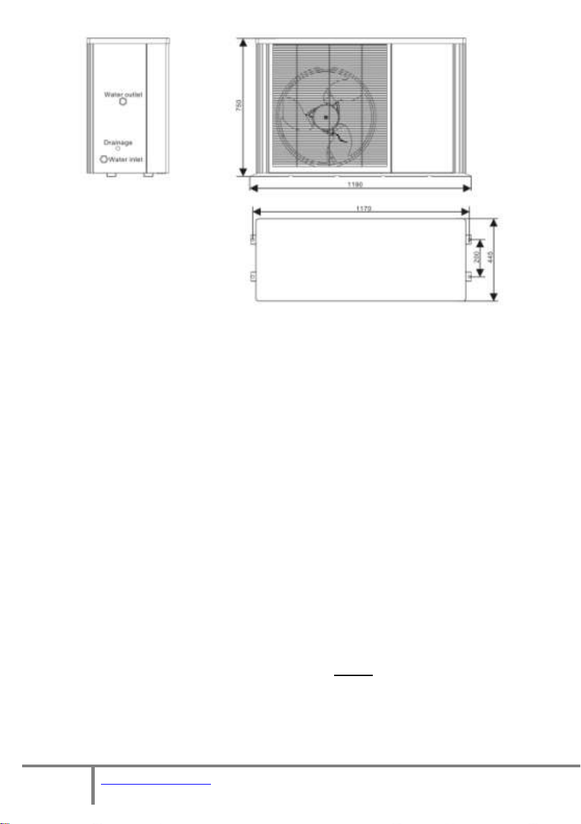
3.1 Appearance of the Unit
3.2 Unit Dimensions
4.0 Choosing the right heat pump
4.1 Heat Load Calculation
4.2 Varimax Output Rating
4.3 Emitter systems
5.0 Installation
5.1 Where to use and Where to Site the unit
5.2 Location of the Unit
5.3 Transporting the Unit
5.4 Plumbing Considerations
6.0 Hydraulic Connection
6.1. Expansion vessels
6.2 Flow Switch
6.3 . Flexi Hoses
6.4 Automatic bleed valves
6.5 Transit Bung
6.6 Y-Strainer
6.7 TRVs
6.8 Distribution Water Pump
6.9 Glycol
7.0 Electrical Connection
7.1 Warning Notes
7.2 MCB
7.3 Isolation Switch
7.4 Cable Routing
7.5 Before You Start
7.6 Wiring-in The Unit
8.0 Unit Specifications
9.0 Commissioning
Page 4

4 of 52
V 1.7
www.esavep.com PASRW040-D-BP
9.1 Pre-Start Checks
9.2 Switching on the Unit
10.0 UNIT CONTROLLER
10.1 main Interface
10.2 Basic Operation
10.3 Main Menu
10.4 Frequency Control
11.0 Maintenance
11.1 Essential Checks
11.2 Advisory Checks
12.0 Trouble Shooting
12.1 Error Codes
12.2 Simple Faultfinding
13.0 Wiring Diagram
14.0 Guarantee
14.1 Guarantee Terms
15.0 Environmental Information
16.0 Adding a Remote Wired Controller
17.0 Weather Compensation
18.0 Performance
19.0 Parameter List
Page 5

5 of 52
V 1.7
www.esavep.com PASRW040-D-BP
1.0 Preface:
This manual includes all the necessary information about installation and
maintenance of the ESP Varimax I inverter driven air source heat pump
(ASHP) unit. Please read this manual carefully before carrying out any
installation or maintenance works on the unit. Please note that, failure to
observe the provisions in this manual will invalidate any warranty on the
unit and may lead to loss and/or damage to people and/or property that
ESP will not be liable.
All ESP ASHPs are covered by the warranty contained in the ESP Terms and
conditions of Business a copy of which will have been provided to you prior
to your purchase.
The Varimax I must only be installed by suitably qualified personnel.
The Varimax I air source water heat pump is a high efficiency, energy
saving and environmentally friendly unit that should be used primarily for
space heating. It can work with any kind of heat emitter unit such fan coil,
radiator, or under floor heating. The Varimax I can also be used to
generate domestic hot water (DHW) for sanitary purpose although ESP
recommend that space heating is achieved with an ASHP and the DHW
requirement be met by an ESP Ecocent unit. PLEASE NOTE that operating
conditions, such as ambient air temperature, required water flow
temperatures, target room temperatures and humidity will influence the
operating efficiency of the unit.
1.1 Features of the Varimax I ASHP:
1. Advanced controls
All user set parameters can be controlled via A PC based controller
that can control several units simultaneously.
2. Attractive appearance
The Varimax I is designed to be attractive and
discrete.
3. Compact design
Our Varimax I units have a built-in water pump
and is a stand-alone unit to make installation
simple and quick.
4. Quiet running
High quality and efficient compressors, fans, water pumps and
Page 6

6 of 52
V 1.7
www.esavep.com PASRW040-D-BP
sound insulation combines to ensure a very low running noise of 59
dBa.
5. Heat Exchanger
The Varimax I unit is equipped with a very high efficiency heat
exchanger to deliver exceptional efficiency.
6. Wide operating temperature capability
The Varimax I unit is designed to work effectively and efficiently
down to -15°C ambient air temperature.
2.0 SAFETY PRECAUTIONS
Please note the following important installation and operating
information: Failure to observe these points could lead to loss or
damage to property and/or injury/death of installers/operators and
will invalidate the warranty.
The unit must only be installed, moved and/or repaired by a
suitably qualified and experienced engineer. If you are in
doubt about who is qualified carry out works on the Varimax
I unit, please call ESP.
The Unit MUST be properly earthed.
Do not put fingers or other objects in to the grille covering
the fan and make sure that children do not play close to the
unit. The grills are there for a good reason.
If you hear abnormal noises, or smell strange odours, coming
from the unit, switch it off immediately and call your installer
or ESP.
Do NOT install the unit close to any gas fired appliance,
heater or fire.
Ensure that the base on which the unit is secured is both
large and strong enough to take the weight of the unit
comfortably and will not subside. The base should also be at
least 150mm above the surrounding ground level and you
Page 7
7 of 52
V 1.7
www.esavep.com PASRW040-D-BP
should check the base periodically to ensure that there is no
subsidence of the base. In areas prone to flooding, care
should be taken to ensure that the unit is elevated to avoid
flood damage.
Ensure that you use a suitably rated circuit breaker. If in
doubt, have your electrician call ESP Technical Support.
Switch off the power before carrying out any cleaning and/or
maintenance.
3.0 VARIMAX I UNIT SPECIFICATIONS
3.1 APPEARANCE OF THE UNIT
Unit
controller
The maximum length of cable for the unit controller is 200 metres
from the heat pump
Page 8
8 of 52
V 1.7
www.esavep.com PASRW040-D-BP
3.2 UNIT DIMENSIONS
4.0 Choosing the right heat pump
4.1 Heat Load Calculation
Based on the local climatic conditions, construction features and
insulation levels, your system designer will calculate the heat load
and, therefore, the appropriate unit size for your building. ESP can
provide a heat load calculation that conforms to MIS 3005. For new
builds, the requirements of Part L of The Building Regulations (or
better) for insulation will help ensure that the heat load of the
dwelling is kept to a minimum. For existing buildings, insulation
should be improved as much as possible to minimise the heat load.
4.2 Varimax Output Rating
The Varimax I operating capability rating has been based upon the
test conditions set out in BS EN 14511 and you should choose your
unit according to the rated output. Please NOTE that BS EN 14511
rates unit output based upon 6/7°C ambient air temperature and
you must ensure that you size your unit based upon the conditions
stated in MIS 3005. Performance graphs are included in section 18.
Page 9

9 of 52
V 1.7
www.esavep.com PASRW040-D-BP
Make sure that your supplier/installer is familiar with the
requirements of MIS 3005.
The Varimax I unit is MCS Accredited and, if you wish to take
advantage of certain funding that may be available, your unit MUST
BE INSTALLED BY AN MCS ACCREDITED INSTALLER – please consult
your supplier or ESP should you require further clarification.
4.3 Emitter system.
The Heat pump must be matched to a suitable emitter system.
Guidance on choosing a suitable system can be found at
www.microgenerationcertification.org\admin\documents\MIS
3005 Supplementary Information 2 - Heat Emitter Guide v2.0.pdf
where guidance on pipe spacing for UFH systems and sizing
consideration for fan coil units such as the ESP Thermovec and
traditional wet radiators can be found.
5.0 Installation
5.1 Where to use and Where to Site the unit
The Varimax I can be used for domestic or commercial premises
and you should consider the following when choosing an
installation site:
The unit must be installed in an outdoor location on a
solid base that can carry the weight of the unit. This can be
on the ground, a roof or balcony. If it is to be installed on a
roof or balcony, a steel frame must be used. Please contact
ESP for further details.
The must be well ventilated but NOT windy.
The site should be away from direct sunlight and sources
of high heat.
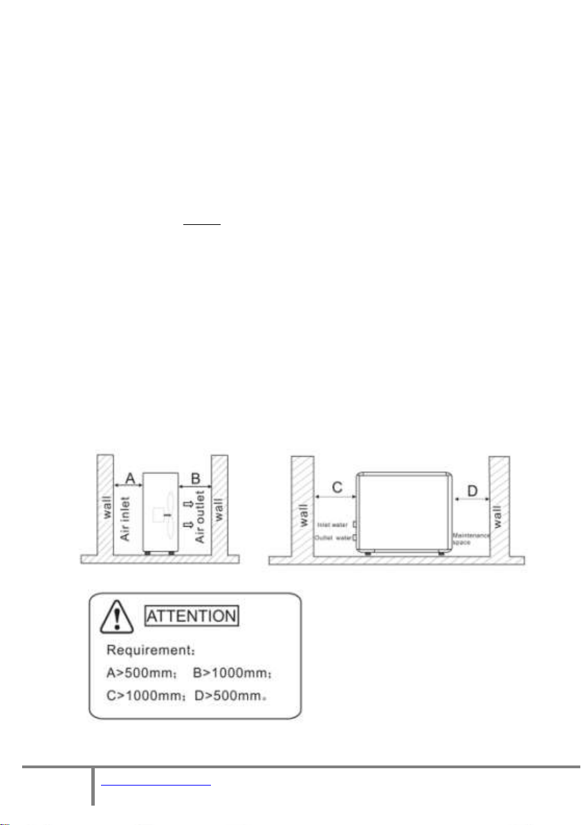
The unit must be sited 500mm from any obstacles to the
rear and sides. Further information is included in the section
below entitled “Location of Unit”.
Page 10
10 of 52
V 1.7
www.esavep.com PASRW040-D-BP
Rear of Unit
The unit generates condensate and this should be piped
away from the unit and in to a suitable drain to prevent ice
forming on the area around the unit. This applies to the
water resulting from a defrost cycle.
There must be enough space around the unit for
plumbing and maintenance works as detailed in the diagram
below.
The unit MUST be firmly fixed to a secure base using the
rubber anti-vibration feet using suitable fixings. Failure to
secure the unit properly using the rubber feet will mean that
it will fail accreditation.
To allow precipitation to run off the unit and to ensure
that any water entering the unit can drain through the holes
in the bottom of the unit, allow a 3mm fall left to right as you
look at the fan.
5.2 Location of the Unit
Page 11
11 of 52
V 1.7
www.esavep.com PASRW040-D-BP
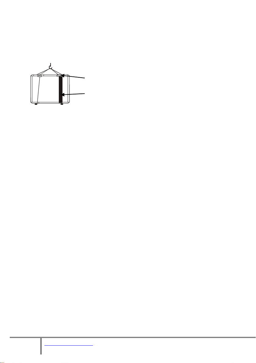
5.3 Transporting the Unit
8m lifting web
Soft Protection
When lifting the unit during installation and transportation, an 8
meter strap must be used and the unit protected by soft material
placed between the lifting strap and the unit to prevent damage.
(See picture below).
5.4 Plumbing Considerations
When planning the plumbing for the unit, please consider the
following points:
Whenever possible, limit the number of bends in
pipework.
The pipework must be clear and free from debris and
blockages. Pipework should be hot flushed before the unit is
connected. Failure to observe this precaution will invalidate the
warranty.
Pipework must be tested for leaks before being connected
to the unit. Pressure testing must be carried before the unit is
connected to avoid damage to the unit. Failure to observe this
precaution will invalidate the warranty.
There must be an expansion vessel included in the design
of the system. The correct sizing of the expansion vessel(s) must
be determined by the installer and must include the volume of
water/glycol in all distribution pipework, emitters, the buffer
tank, pipe work between the unit and the buffer tank and all
other volumes.
Automatic bleed valves should be fitted at the highest
Page 12

12 of 52
V 1.7
www.esavep.com PASRW040-D-BP
points within the system and at any place within the pipework
that may be likely to hold air blocks. Manual air vents should
be fitted at the highest point on the pipework between the
unit and the buffer tank and at any point that presents air lock
potential.
It is highly recommended that a suitably sized buffer
tank be installed between the unit and the heating
distribution system. Please consult your installer or ESP when
considering this system design point – the right sized buffer
tank can make a significant difference to the economy and
efficiency of the unit and the heating effectiveness.
6.0 Hydraulic Connection
6.1. Expansion vessels.
An expansion vessel must be installed where the heating system is
unvented. The size of the vessel(s) must be t=determined by the installer
on site and take into account the entire volume of water/glycol mix being
heated including the volumes contained in the Unit, the buffer tank, the
distribution system, emitters and any other system connected to the unit..
6.2 Flow Switch
The unit is fitted with a water flow switch that will pause the unit
operation if water flow is not continuous (this includes where there is air
in the system). The flow switch is there to protect the unit and the
setting should not be altered. If the flow of water is insufficient, an
error code of “Flow Level” will be displayed on the controller. This will
occur on initial start-up if the installer has failed to purge all the air from
the system.
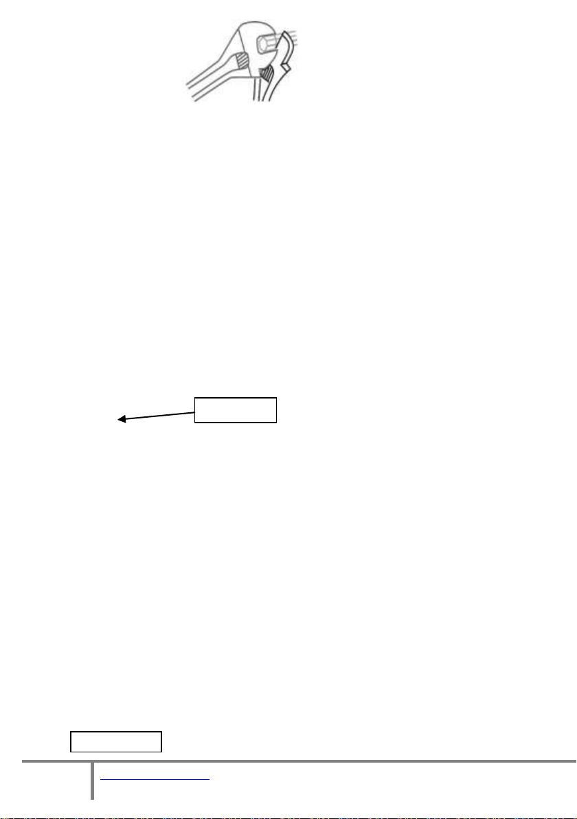
6.3 . Flexi Hoses
The final connection to the heat pump flow and return must be made with
suitable flexible pipes to prevent vibration in to the system pipework.
Please ensure that two wrenches are employed to take up the torque
created in tightening the fittings to avoid damage to both the fittings and
the heat pump.
Page 13
13 of 52
V 1.7
www.esavep.com PASRW040-D-BP
These flexible hoses are available from ESP as part of an Installation Pack
Transit Bung
Spirotrap Strainer
or individually.
6.4 Automatic bleed valves
Make sure that you fit automatic bleed valves (air vent)s at high points in
the system. The unit will shut down if air is in the system because the
water flow switch will recognize air in the system as no water flow and a
system alarm/protection code will appear on the unit controller. The
Error Message “Flow Level” will appear on the controller display.
6.5 Transit Bung
The unit is supplied with a transit bung beside the
flow/return pipes.
This bung must be removed and replaced with a drain-off- cock (DOC).
There must also be a DOC at any lower point in the system, to allow for
effective drain-down of the system as and when required. Please note
that, if the system is to be left idle for a long period in winter, the system
should be drained down. You should fit full flow lever valves on the flow
and return to the unit so that the unit can be quickly and effectively
drained down where required for maintenance.
6.6 Y-Strainer
You must fit a Y-strainer on in-line on the return pipe to
the unit. This is normally fitted in an external location
and must have a full flow lever valve side either side of
the strainer to minimise glycol loss during maintenance.
Due to the mix of metals on many systems it is both
advisable and preferable to install a Spirotrap ® rather
than the minimum standard Y strainer. Failure to fit a
Page 14

14 of 52
V 1.7
www.esavep.com PASRW040-D-BP
good quality strainer in the return flow to the unit will invalidate the
% Glycol
10
20
30
40
50
Ambient Temp
-3
-8
-14
-22
-33
Heating Capacity Fluctuation
.991
.982
.972
.961
.946
Power Input Fluctuation
.996
.992
.986
.976
.966
Water Flow Fluctuation
1.013
1.040
1.074
1.121
1.178
Water Drop Fluctuation
1.070
1.129
1.181
1.263
1.308
warranty on the unit.
6.7 TRVs
Where standard steel radiators are to be fitted, careful consideration
should be given before using Thermostatic Radiator Valves (TRVs) because
they are not designed to be used with low temperature systems. If the
decision is taken to use TRVs, one should NOT be fitted in the same room
as a room thermostat.
6.8 Distribution Water Pump
If, as advised, you are using a buffer tank in the system, you will need to
fit a suitably sized water pump on the water distribution side of the
system. This water pump will need to be wired to receive an appropriate
signal from the heating system.
6.9 Glycol
The system must be protected from freezing by using a glycol solution in
the water circuits. The glycol/water should be added into the system
from the expansion tank of the water loop or via the top of the buffer
tank. The following table details the volume of the glycol/water solution
mix:
Note: if the glycol/water mix is too strong, the water flow and water
pump will be affected and the efficiency of the unit will be
decreased. The above table is for reference only and you should use
a glycol/water solution that is suited to local conditions.
Page 15

15 of 52
V 1.7
www.esavep.com PASRW040-D-BP
7.0 Electrical Connection
7.1 Warning Notes
IMPORTANT! All electrical work MUST be carried out by a suitably
qualified electrician. We know that suitably qualified electricians charge
professional level fees for work that they carry out, but it is better to pay a
professional/fully qualified electrician to connect your unit in to an
appropriate power supply in the correct way, than for you to die trying or
as a result of a fire in your property caused by inappropriate or incorrect
electrical works. Also, it is law that only qualified electricians should
install, repair or maintain electrical connections and, if you do not kill
yourself installing the unit, you run the risk of prosecution if you do not
comply with the law. It is not an exaggeration to say that, if you
install/connect your unit to a power supply and that
installation/connection causes injury to, or death of someone (even years
after installation), you can be prosecuted under criminal law for murder,
manslaughter or bodily harm and spend many years in prison as a result.
IT IS NOT WORTHWHILE RUNNING THIS RISK.
SO, GET YOUR UNIT WIRED IN BY A PROFESSIONALLY QUALIFIED
ELECTRICIAN IF YOU DO NOT KNOW SOMEBODY THAT IS QUALIFIED TO
DO THE WORK, FIND SOMEONE AND DO NOT BREAK THE LAW BY DOING
THE WORK YOURSELF.
7.2 MCB
The connection to the electrical consumer unit in the property must
comply with current electrical standards and Regulations and be done via
a dedicated breaker on the consumer unit that corresponds to the heat
pump electrical capacity. Failure to do this correctly can result in fire
and/or permanent damage to the unit. If the unit is not appropriately
wired in to a suitable supply, the warranty on the unit will be voided. The
MCB must be a type C 24 Amp MCB.
Page 16

16 of 52
V 1.7
www.esavep.com PASRW040-D-BP
Typical Isolation Switch
7.3 Isolation Switch
The heat pump MUST be connected to the power supply through a two
port rotary isolation switch a two port rotary that
has at least a 3mm contact separation at all poles,
fixed in close proximity to the unit and suitably
positioned for general and emergency use as
required by relevant Regulations. The switch must
NOT be attached to the unit itself. The isolation
switch must be suitable for the unit electrical duty and comply with
applicable Regulations.
7.4 Cable Routing
All wiring should be routed neatly, be kept as far away as possible from
the units water pipes and valves and comply with relevant Regulations.
High voltage and low voltage wiring should be clearly separated.
7.5 Before You Start
Before starting to wire in the power supply to the unit, please check that
the power supply is suitable for the unit (e.g. single phase, correct size
cable, MCB etc. is available) having taken into account the requirements
of the entire site. The unit power specification is stated on a label on the
side of the unit. We recommend the use of a dedicated 32 Amp Type C
MCB for connection of the power supply to the consumer unit.
7.6 Wiring-in The Unit
The following points should be noted in relation to power supply wiring
and system components:
Open the front and top panels to access the electrical
connection terminals.
The power supply must go through the protective wire aperture
in the unit casing and be connected securely to the terminals in
the control box.
Page 17

17 of 52
V 1.7
www.esavep.com PASRW040-D-BP
Terminals 24/25
Mains power
Connector Cover
Mains power
Connector Block
In section 13 you will find wiring diagrams for the unit and, in
section 16, instruction on how to connect a remote controller to
the rear of the Carel controller. Please use these diagrams when
introducing power or other wiring into the unit. You should also
use these diagrams to check the installation through before
starting the unit for the first time.
Part L2 of The Building Regulations requires that the heating
system be fitted with a 7 day programmer. However, the most
efficient way of running an ASHP heat system is to set the
programmer to ALWAYS ON. An L2 compliant programmer may
be used but it is very IMPORTANT that any signal going back to
the heat pump from the heating system thermostat and/or
programmer must be VOLT FREE ! The heating system
thermostat/ programmer controller is wired to terminals 24&25
inside the heat pump (these connections are not polarized) If
you do not use a volt free programmer you WILL damage the
ASHP unit.
Page 18

18 of 52
V 1.7
www.esavep.com PASRW040-D-BP
Model Designation
PASRW040B-D-BP
Heating Capacity
Kw
4.2~12.3
BTU/h
14200~41800
Heating Power Input
Kw
1.06~2.8
Max. Running Power
Consumption
A
12.0/12.2
Power Supply
V/Ph/Hz
230/1/50
Number of Compressors
1 Compressor Type
Rotary
Number of Fans
1
Fan Power Input
W
75
Fan Speed
RPM
830
Noise
dB(A)
56
Water Pump Power Input
Kw
.02
Water Head
M
6.5
Water Connection
Inch
1
Water Flow Volume
m3/h
1.7
Water Pressure Drop
KPa
34
Unit Dimensions
mm
See Drawings
Unit Shipping
Dimensions
mm
See Package Label
Net Weight
Kg
See Unit Label
Shipping Weight
Kg
See Package Label
The unit MUST be connected to the master thermostat within
the building that controls the call for heat. If you do not have a
master thermostat connected to the unit from the building, the
unit will run inefficiently and, in some case, not at all.
8.0 Unit Specifications
9.0 Commissioning
9.1 Pre-Start Checks
The following checks must be made prior to starting up the unit for
the first time:
Page 19

19 of 52
V 1.7
www.esavep.com PASRW040-D-BP
Check that all relevant lever valves are open.
Check the water loop and expansion tank to ensure that both
have adequate water in them to allow the system to operate
at 1 – 1.5 bar.
Ensure that all air has been purged from the system.
Ensure that pipes are well insulated using waterproof lagging,
with at least 30mm wall thickness.
Check the electrical wiring is correct in every respect. In
particular, make sure that the system is properly earthed.
Inspect the heat pump to ensure that all screws cover have
been replaced and secured properly.
Check that the fan rotates freely.
When you switch on the power to the unit at the rotary
isolation switch, check the controller on the unit casing to see
if there is an error code being displayed.
9.2 Switching on the Unit
Please familiarise yourself with the unit controller and the
instructions in section 10 so that you can check various
parameters as the unit starts.
Start the heat pump by pressing the " " key on the unit
controller (see section 10). This will start the water pump.
Check that the water pump is running - there should be a
reading of 0.2 MPa on the water pressure gauge.
When the water pump has been running for 1 minute, the
Page 20

20 of 52
V 1.7
www.esavep.com PASRW040-D-BP
compressor will start up. Make sure that there are no strange
noises coming from it
. If the compressor sounds abnormal,
stop the unit immediately and check the compressor. If the
compressor runs well please check the pressure of the
refrigerant.
Following the above, check whether the power input and
running current being drawn by the unit is in line with this
manual. If not please stop the unit and check for any
problems.
If the unit is supplying a heating manifold, adjust the
actuators on the manifold(s) to balance the heating being
received in all areas of the system.
Check that the outlet water temperature is stable and
increasing smoothly towards the target temperature. The
return water temperature should move in line with the flow
temperature with around a 4 deg C. difference between the
flow and return water temperatures.
The parameters of the unit controller are factory set and you
must not change them without consulting your installer or
ESP. The exceptions to this are the running temperature (or
flow temperature) of the system and the time. Section 10
explains how to view the various parameters although the
default view will show the current status of the system (see
10.1).
Page 21

21 of 52
V 1.7
www.esavep.com PASRW040-D-BP
10.1 Main Interface
10.2 Basic operation
10.0 UNIT CONTROLLER
Page 22

22 of 52
V 1.7
www.esavep.com PASRW040-D-BP
Page 23

23 of 52
V 1.7
www.esavep.com PASRW040-D-BP
Page 24

24 of 52
V 1.7
www.esavep.com PASRW040-D-BP
10.3 Main Menu
Page 25

25 of 52
V 1.7
www.esavep.com PASRW040-D-BP
Page 26

26 of 52
V 1.7
www.esavep.com PASRW040-D-BP
Page 27

27 of 52
V 1.7
www.esavep.com PASRW040-D-BP
Page 28

28 of 52
V 1.7
www.esavep.com PASRW040-D-BP
Page 29

29 of 52
V 1.7
www.esavep.com PASRW040-D-BP
Page 30

30 of 52
V 1.7
www.esavep.com PASRW040-D-BP
Page 31

31 of 52
V 1.7
www.esavep.com PASRW040-D-BP
Page 32

32 of 52
V 1.7
www.esavep.com PASRW040-D-BP
Page 33

33 of 52
V 1.7
www.esavep.com PASRW040-D-BP
Page 34

34 of 52
V 1.7
www.esavep.com PASRW040-D-BP
Page 35

35 of 52
V 1.7
www.esavep.com PASRW040-D-BP
Page 36

36 of 52
V 1.7
www.esavep.com PASRW040-D-BP
Page 37

37 of 52
V 1.7
www.esavep.com PASRW040-D-BP
10.4 Frequency Control
Page 38

38 of 52
V 1.7
www.esavep.com PASRW040-D-BP
Parameters R01-R04
should be set according to
the following table:
Par
Description
Limits
R01
Cooling set-point
12°C
R02
Cooling differential
2°C
R03
Heating set-point
40°C
R04
Heating differential
2°C
Page 39

39 of 52
V 1.7
www.esavep.com PASRW040-D-BP
11.0 Maintenance
11.1 Essential Checks
Periodically clean the water filter; this will need to be every month for the first 6
months following start up of the system to allow installation debris to be extracted.
NOTE that a lack of water in the system or debris/dirt entering the system can
damage the unit.
11.2 Advisory Checks
Although there is no formal requirement for annual maintenance of the
unit, the following checks are strongly suggested:
Check the water supply and air vents frequently, to ensure that there is
adequate water within the system and that air is kept out of the system.
Check each part of the unit and the pressure within the system.
If any component has failed, replace it (and recharge refrigerant, if any has
been lost).
Check over the power supply and the electrical system generally to make
sure that no wires are lose or degrading. You must investigate any scorching
or unusual smells coming from the unit or the wiring.
Replace any part that may be malfunctioning; it is better to replace a part
early (to practice good preventative maintenance) than await failure.
If the heat pump is not to be used for a long period of time, please drain it
down and seal the unit to keep it safe for recharging and restarting when
needed.
If a period of non use will include any possibility of the unit freezing, isolate
the unit and drain the water from the lowest point of the heat exchanger.
Recharge the water/glycol and carry out a full inspection of the unit before
it is restarted.
The water loop of the heat pump MUST be protected from freezing in
Page 40

40 of 52
V 1.7
www.esavep.com PASRW040-D-BP
winter. Please NOTE THE FOLLOWING – failure to observe the following
Malfunction
Display
Re ason
Re solutio n
Inlet probe error
or no t conne ct ed
P1
The sensor is ope n
or sho rt circuit
Check or change the
sensor
Outlet probe 1
error or not
connected
P2
The sensor is ope n
or sho rt circuit
Check or change the
sensor
Outlet probe 2
error or not
connected
P3
The sensor is ope n
or sho rt circuit
Check or change the
sensor
Dischar ge probe
error or not
connected
P4
The sensor is ope n
or sho rt circuit
Check or change the
sensor
Co ndens er probe
1 error or not
connected
P5
The sensor is ope n
or sho rt circuit
Check or change the
sensor
Co ndens er probe
2 error or not
connected
P6
The sensor is ope n
or sho rt circuit
Check or change the
sensor
External p robe
error or not
P7
The sensor is ope n
or sho rt circuit
Check or change the
Wa ter f low a larm
E1
Wa ter f low rate i s
inadequat e
Check the w at er flow
volum e, and f low
switc h op er at io n
Inverter
compresso r low
L1
Low p re ssure
switc h actio n
Check through eac h
pressure sw itch and
Inverter
compresso r hi gh
pressure alarm
H1
High pressure
switc h actio n
Check through eac h
pressure sw itch and
retur n circuit
requirements WILL invalid the warranty for the heat pump.
Please do not shut off the power supply to the heat pump in winter unless it is to
be drained-down. When the air temperature is below 0°C, if the inlet water
temperature is above 2°C and below 4°c, the water pump will start automatically
once in every 72 hrs to provide frost protection.
12.0 Troubleshooting
12.1 Error Codes
The unit controller has the capability to identify problems within the unit
and/or system and you should take note of any ‘Error’ codes displayed.
The following table will aid fault diagnosis:
Page 41

41 of 52
V 1.7
www.esavep.com PASRW040-D-BP
Failure
Possible caus es for the
failure
Solut io ns
He at pump
can not
be s tar ted
1 Wro ng po wer s up ply
2 pow er sup ply ca ble loo se
3 cir cuit b rea ker op en
1 shu t off the po we r and che ck p ower sup ply ;
2 che ck power c able and mak e ri gh t con nect io n
3 ch eck for the ca us e and re pl ace the fu se o r cir cuit
br eak er
Wat er pump is
ru nni ng wi th
hi gh no ise or
wi tho ut wa ter
1 lac k of wat er i n the pi pin g
2 muc h air in the w ate r loop
3 wat er valv es cl ose d
4 dirt and block on the wate r fil ter
1 ch eck the w ater su ppl y and char ge wate r to the p ipi ng;
2 dis charge the ai r in the w ater loo p;
3 ope n the va lve s in wa ter lo op ;
4 cle an the w ate r fil ter.
He at pump
cap acit y is low,
com pres sor
do not s top
1 lac k of ref ri ger ant;
2 bad ins ula tio n on wat er pipe;
3 low heat e xch ange r ate o n air si de
exc han ger;
4 lac k of wat er fl ow
1 ch eck for the gas le akage an d rechar ge the ref ri geran t;
2 mak e goo d ins ul ati on on wa ter pipe;
3 cle an the air s id e heat e xch an ger ;
4 cle an the w ate r fil ter
Hi gh
com pres sor
exh aust
1 too mu ch re fri gera nt
2 low heat e xch ange r ate o n air si de
exc han ger
1 dis charge the r edund an t gas
2 cle an the air s id e heat e xch an ger
Low pr ess ur e
pr obl em
of the sy stem
1 lac k of gas
2 blo ck on f il ter or capi ll ary
3 lac k of wat er fl ow
1 che ck the gas le ak age and rec harge fre on ;
2 rep lac e filter or c apil lary;
3 cl ean the w ater fi lte r and di sch arge th e air in wa te r loo p.
Co mpr esso r do
not run
1 pow er sup ply fa ilu re
2 com press or co nta ctor br oke n
3 pow er cab le l oose
4 pro tec ti on on co mp res sor
5 wron g setti ng on r etu rn wa ter t emp.
6 lac k of wat er fl ow
1 che ck off the p ower s up pl y;
2 rep lac e comp resso r con tac tor;
3 tig ht en the p ower c able;
4 che ck the c omp ress or ex hau st tem p.;
5 res et the re tur n water t emp .;
6 cl ean the w ater fi lte r and di sch arge th e air in wa te r loo p.
Dischar ge tem p.
Too high
Exhaust
tempe ra ture is too
high
Check through eac h
temp. switc h and
retur n circuit
Freez e alarm
Wa ter f low rate is
inadequat e
Check the w at er flow
volum e and flow
switc h op er at io n,
Power fault
alarm
Not used in
single phase uni t
Outlet tem p. t oo
cold
Wa ter f low rate i s
inadequat e
Check the w at er flow
volum e, and f low
Compressor 2
overcold
Wa ter f low rate i s
not e no ug h
Check the w at er flow
volum e and flow
EEV alarm
Suction p ro be
error
The sensor is ope n
or sho rt circuit
Check or change the
sensor
EEV alarm
Evap. P ro be
error
The sensor is ope n
or sho rt circuit
Check or change the
sensor
2
)
L
o
o
k
*
.
*
.
2
12.2 Simple Faultfinding
The following is a list of some basic faults and solutions.
Page 42

42 of 52
V 1.7
www.esavep.com PASRW040-D-BP
Hi gh no ise of
com pres sor
1 liq ui d refr iger an t goe s into com pr ess or
2 com press or fa il ure
1 bad evap ora ti on, c he ck the ca us e for bad e vap orati on
and get rid of th is ;
2 use new comp res sor;
Fan does not run
1 fai lu re on fan rela y
2 fan mot or br oke n
1 rep lac e the fan rel ay;
2 rep lac e fan m otor.
The com pres sor
ru ns but he at
pump has no
he ati ng or
coo li ng c apa cit y
1 no gas in the heat p um p;
2 hea t exch ange r br oke n;
3 com press or fa il ure .
1 che ck sy stem l eak age and rec harg e refr ig era nt;
2 fin d out the c aus e and rep lac e the heat e xch ange r;
3 rep lac e comp resso r.
Low out le t wat er
tem pe rat ur e
1 low wat er fl ow r at e;
2 low set tin g for the de si red wa te r tem p. ;
1 cl ean the w ater fi lte r and di sch arge th e air in wa te r loo p.
2 res et the de si red wate r tem pe rat ur e.
Low wat er fl ow
pr ote cti on
1 lac k of wat er i n the sys tem;
2 fai lu re on f low s wit ch
1 cl ean the w ater fi lte r and di sch arge th e air in wa te r loo p.
2 rep lac e the flo w sw itc h.
Page 43

43 of 52
V 1.7
www.esavep.com PASRW040-D-BP
13.0 Wiring Diagram
Page 44

44 of 52
V 1.7
www.esavep.com PASRW040-D-BP
14.0 GUARANTEE
Should any factory fitted Temperature and/or Pressure Relief Valve(s) or
other safety devices be tampered with or removed or any recommended
Temperature or Pressure Relief Valves/safety devices not be fitted, your
warranty/guarantee will be invalidated. Neither the Distributor nor
Manufacturer shall be responsible for any damage resulting from the
tampering, howsoever caused, save where such exclusion is unlawful.
14.1 GUARANTEE TERMS
ESP warrants/guarantees the electrical parts, thermal controls and valves
relating to the cylinder for a period of one year from the date of purchase
,
with the exception of normal wear and tear including any damage caused as
a result of lime scale deposits.
The stainless steel vessel forming part of the cylinder is
warranted/guaranteed for a period of five years against faulty manufacture
or materials provided that:
i) It has been properly installed by a competent installer as per th
e
instructions and recommendations contained in this manual and all r
elevant codes of Practice and Regulations in force at the time of
installation.
ii) It has not been modified in any way other than by ESP.
iii) It has only been used for the storage of wholesome water.
iv) It has not been installed in a location liable to be subjected to fro
st, nor has it been tampered with or been subject to misuse or
neglect.
v) No factory fitted parts have been removed for unauthorised repai
r or replacement.
Page 45

45 of 52
V 1.7
www.esavep.com PASRW040-D-BP
vi) Within 45 days of purchase the user completes and returns the
registration certificate.
The compressor in the heat pump is warranted/guaranteed for 2 years
from the date of purchase. Remaining parts of the heat pump are
warranted/ guaranteed for 1 year from the date of purchase.
Evidence of purchase and date of supply must be submitted with any
warranty/guarantee claim.
This warranty/guarantee is not valid for installations outside the United
Kingdom or the Republic of Ireland.
Any warranty/guarantee is for replacement parts only.
The purchaser of the unit acknowledges that he/she has seen ESP’s conditions of
supply and has understood them.
All of our units are RoHS approved units.
This guarantee does not affect your statutory rights.
15.0 ENVIRONMENTAL INFORMATION
This product is made from many recyclable materials, therefore at the end of
its useful life, it should be disposed of at a Local Authority Recycling Centre
in order to realise the full environmental benefits.
Please note:
The pace of product development is such that we reserve the right to
change product specifications without notice. We do, however, strive to
ensure that all information in this leaflet is accurate at the time of
publication.
Page 46

46 of 52
V 1.7
www.esavep.com PASRW040-D-BP
16.0 ADDING A REMOTE WIRED CONTROLLER
Should you wish to add a remote, wired controller, the procedure is as follows:
You have to prepare 3 assemblies: the MCH2004850 RS485 card,
the 98C556C006 RJ12 power supply
and the wired controller:
There are 3 preparation steps:
1. Connect the RJ12 power supply to CarelUC2SE with RS485 card.
RJ12
R485
UC2SE
Page 47

47 of 52
V 1.7
www.esavep.com PASRW040-D-BP
The Three signal terminals ”+” , ”-“ and “GND” , must be
matched correctly. If If the distance between the two
controllers exceeds 20m, a 120 Ω must be inserted
between the ‘+’ and ‘-‘.
2. Connect the wired controller to RJ12 power supply.
3. Connect the 24VAC which is on the CarelUC2SE to the RJ12 power supply.
To 24 V AC
Page 48

48 of 52
V 1.7
www.esavep.com PASRW040-D-BP
Done!
In order to get better signal quality over long distances, all the wires
should be twisted pair + Shield.
Page 49

49 of 52
V 1.7
www.esavep.com PASRW040-D-BP
17.0 Weather Compensation:
Page 50

50 of 52
V 1.7
www.esavep.com PASRW040-D-BP
18.0 Performance:
18. Varimax Performance
Page 51

51 of 52
V 1.7
www.esavep.com PASRW040-D-BP
19. Parameter List:
Page 52

52 of 52
V 1.7
www.esavep.com PASRW040-D-BP
CONTACT DETAILS
Earth Save Products Technical Team – 01235 815569
 Loading...