

Page 1

1 of 41
V 1.0
www.esavep.com PASRW060-D-BP
ESP VARIMAX 20 ASHP
Installation and
Operation Manual
Page 2

2 of 41
V 1.0
www.esavep.com PASRW060-D-BP
WARNING !
READ THIS BEFORE
INSTALLING
THE UNIT.
The installation of all un-vented water heating systems above 15 litres
MUST comply with local area Building Regulations. It is a legal
requirement that the local Building Control Officer be notified of any
proposed installation.
UK regulations require an appropriately sized expansion vessel
(internal or external) to be incorporated, safety devices to prevent the
stored water exceeding 100°C, and pipe work to convey discharged hot
water safely away from the safety devices.
Furthermore, the installation must be carried out by an engineer who
has successfully completed a recognised course in the installation of
un-vented heating systems such as CITB. Failure to fit the unit
correctly and in accordance with regulations may affect its safety,
efficiency and WILL invalidate any guarantee.
THE UNIT MUST BE INSTALLED, COMMISSIONED AND MAINTAINED BY A
COMPETENT INSTALLER IN ACCORDANCE WITH BUILDING REGULATION
G3 (ENGLAND AND WALES), TECHNICAL STANDARD P3 (SCOTLAND) OR
BUILDING REGULATION P5 (NORTHERN IRELAND) AND THE WATER
FITTING REGULATIONS (ENGLAND AND WALES) OR WATER BYELAWS
(SCOTLAND). FOLLOWING INSTALLATION AND COMMISSIONING, THE
OPERATION OF THE UNIT SHOULD BE EXPLAINED TO THE USER AND
THESE INSTRUCTIONS LEFT WITH THEM FOR FUTURE REFERENCE.
Page 3

3 of 41
V 1.0
www.esavep.com PASRW060-D-BP
Contents:
1.0 Preface
1.1 Features of the Varimax 20 ASHP
2.0 Safety Precautions
3.0 Varimax 20 Specifications
3.1 Appearance
3.2 Dimensions
4.0 Choosing the right heat pump
4.1 Heat Load Calculation
4.2 Varimax 20 Output Statistics
4.3 Emitter systems
5.0 Installation
5.1 Where to use and Where to Site the unit
5.2 Location of the Unit
5.3 Transporting the Unit
5.4 Plumbing Considerations
6.0 Hydraulic Connection
6.1 Expansion vessels
6.2 Flow Switch
6.3 Flexi Hoses
6.4 Automatic bleed valves
6.5 Transit Bung
6.6 In-Line Filter
6.7 Flow Setter
6.8 TRVs
6.9 Distribution Water Pump
6.10 Glycol
7.0 Electrical Connection
7.1 Warning Notes
7.2 Before You Start
7.3 MCB
7.4 Isolation Switch
7.5 Cable Routing
Page 4

4 of 41
V 1.0
www.esavep.com PASRW060-D-BP
7.6 Wiring-in The Unit
8.0 Unit Specifications
9.0 Commissioning
9.1 Pre-Start Checks
9.2 Switching on the Unit
10.0 UNIT CONTROLLER
10.1 main Interface
10.2 Basic Operation
10.3 Start-UP and Shut-Down
10.4 Setting the Target Temperature
10.5 Using the Premium User Interface
10.6 Setting the Time
10.7 Setting the Timers
10.8 Cancelling the Timers
10.9 Checking the Status of the ASHP
10.10 Locking the Display
10.11 Fault Displays
11.0 Maintenance
11.1 Essential Checks
11.2 Advisory Checks
12.0 Trouble Shooting
12.1 Error Codes
12.2 Simple Faultfinding
13.0 Wiring Diagram
14.0 Guarantee
14.1 Guarantee Terms
15.0 Environmental Information
16.0 Weather Compensation
17.0 Performance
18.0 Parameter List
Page 5
5 of 41
V 1.0
www.esavep.com PASRW060-D-BP
1.0 Preface:
This manual includes important information about the installation and
maintenance of the ESP Varimax 20 inverter driven air source heat pump
(ASHP) unit. Please read this manual carefully before installing or carrying
out maintenance works on the unit. Please note that, failure to observe the
provisions in this manual will invalidate any warranty on the unit and may
lead to loss and/or damage to people and/or property for which ESP will not
be liable. All ESP ASHPs are covered by the warranty contained in the ESP
Terms and conditions of Business a copy of which will have been provided to
you prior to your purchase.
The Varimax 20 must only be installed by suitably qualified personnel.
The Varimax 20 air source water heat pump is a high efficiency, energy
saving and environmentally friendly unit that should be used primarily for
space heating. It can work with any kind of heat emitter scheme such as
under floor heating, the ESP Thermovec fan coil unit or traditional radiators.
The Varimax 20 can also be used to generate domestic hot water (DHW) for
sanitary purpose although ESP strongly recommend that space heating is
achieved with an ASHP and the DHW requirement be met by an ESP Ecocent
unit. PLEASE NOTE that operating conditions, such as ambient air
temperature, required water flow temperatures, target room temperatures
and humidity will influence the operating efficiency of the unit.
1.1 Features of the Varimax 20 ASHP:
1. Advanced controls
All user set parameters can be controlled via A PC based
controller that can control several units simultaneously.
2. Appearance
The Varimax 20 is designed to be attractive and discrete.
3. Compact design
Our Varimax 20 units have a built-in water pump and are
stand-alone units (monobloc) to make installation simple and quick.
4. Quiet running
Page 6

6 of 41
V 1.0
www.esavep.com PASRW060-D-BP
High quality and efficient compressors, fans, water pumps and sound
insulation combine to ensure a very low running noise of 59 dBa.
5. Efficiency
The Varimax20 unit is equipped with a highly efficient heat exchanger
to deliver exceptional efficiency.
6. Wide operating temperature capability
The Varimax I unit is designed to work effectively and efficiently
down to -10°C ambient air temperature.
2.0 SAFETY PRECAUTIONS
It is important to take the following precautions when planning your
installation, installing and operating the Varimax 20: Failure to observe these
points could lead to loss or damage to property and/or injury/death of
installers/operators and will invalidate the warranty.
The unit must only be installed, moved and/or repaired by a suitably
qualified and experienced engineer. If you are in doubt about who is
qualified to carry out such works on the Varimax 20 unit, please call
ESP.
The Unit MUST be properly earthed.
Do not put fingers or other objects into the grill covering the fan and
make sure that children do not play close to the unit. The grills are
there for a good reason.
If you hear abnormal noises, or smell strange odours, coming from
the unit, switch it off immediately and call your installer or ESP.
Do NOT install the unit close to any gas fired appliance, heater or fire.
Ensure that the base on which the unit is secured is both large and
strong enough to take the weight of the unit comfortably and will not
subside. The base should also be at least 150mm above the
surrounding ground level and you should check the base periodically
to ensure that there is no subsidence of the base or the immediate
surrounds. In areas prone to flooding, care should be taken to
Page 7
7 of 41
V 1.0
www.esavep.com PASRW060-D-BP
ensure that the unit is elevated to avoid flood damage.
Ensure that you use a suitably rated circuit breaker. If in doubt, have
your electrician call ESP Technical Support.
Switch off the power before carrying out any cleaning and/or
maintenance of the unit.
3.0 VARIMAX 20 SPECIFICATIONS
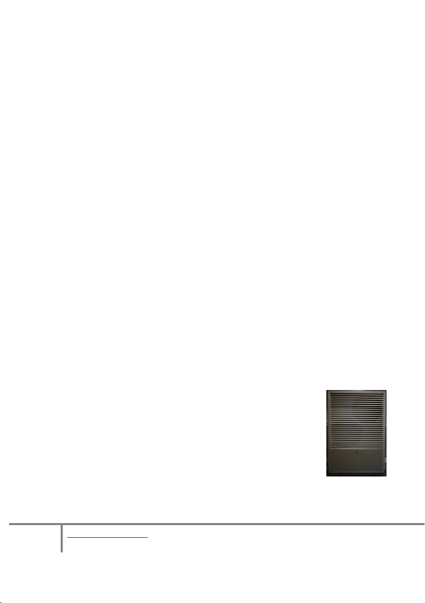
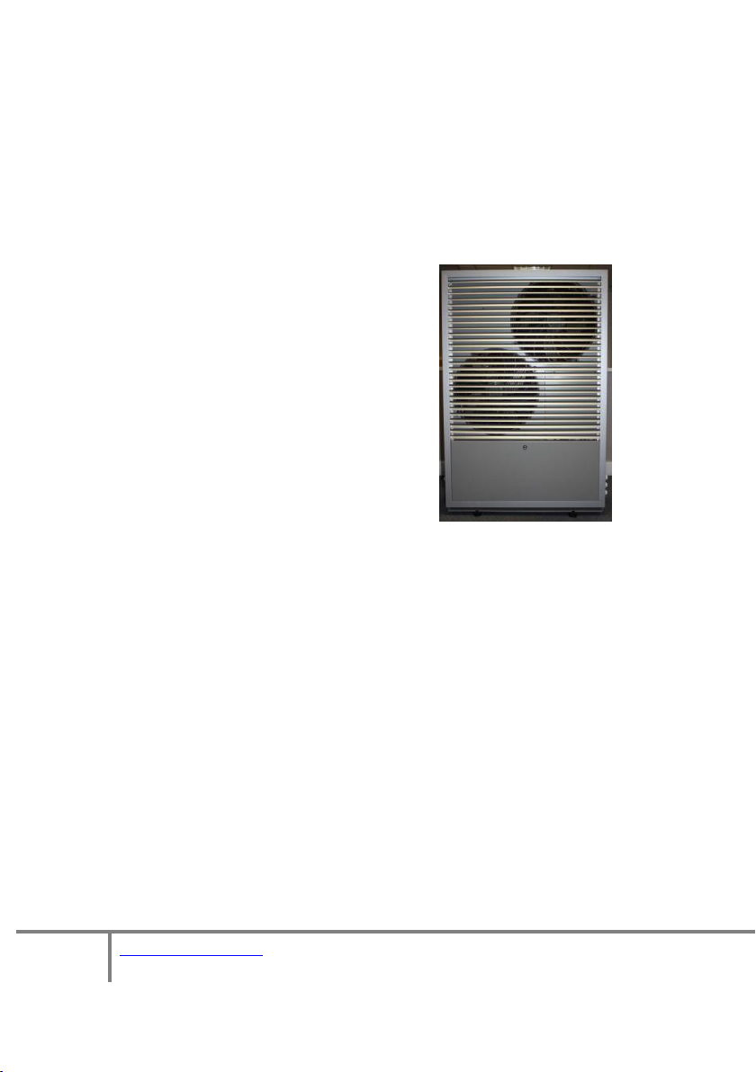
3.1 APPEARANCE
The Varimax 20 is designed to be stylish but
unobtrusive. It can be installed with or
without the front louvre covering the fans.
The cabinet is weather resistant and designed
to look good throughout the life of the unit.
Page 8
8 of 41
V 1.0
www.esavep.com PASRW060-D-BP
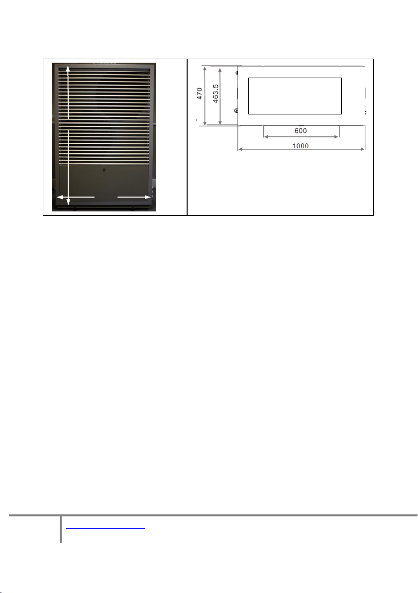
1475
1000
Unit viewed from the
top
3.2 Dimensions
4.0 Choosing the right heat pump
4.1 Heat Load Calculation
Based on the local climatic conditions, construction features and insulation
levels, your system designer will calculate the heat load of your building and,
therefore, the appropriate unit size for your building. ESP can provide a
heat load calculation that conforms to MIS 3005. For new builds, meeting
the requirements of current building regulations for insulation (or better)
will help ensure that the heat load of the dwelling is kept to a minimum. For
existing buildings, insulation should be improved as much as possible to
minimise the heat load.
4.2 Varimax Output Statistics
The Varimax 20 has been tested according to BS EN 14511, EN 14825 and
12102. Additionally it has been tested in accordance with EU Directive
813/2013 to prove the ErP rating. The choice of ASHP for your purposes
should be based upon the output proven by these tests and the conditions
stated in MIS 3005. Performance graphs are included in section 18.
Make sure that your supplier/installer is familiar with the most recent
requirements of MIS 3005.
Page 9

9 of 41
V 1.0
www.esavep.com PASRW060-D-BP
The Varimax 20 unit is MCS Certified and, if you wish to take advantage of
certain funding that may be available, your unit MUST BE INSTALLED BY AN
MCS ACCREDITED INSTALLER – please consult your supplier or ESP should
you require further clarification.
4.3 Emitter system.
The Heat pump must be matched to a suitable emitter system. The
Microgeneration Certification Scheme website offers guidance on pipe
spacing for UFH systems together with sizing consideration for fan coil units
such as the ESP Thermovec and traditional wet radiators can be found.
Please note that, in the case of an UFH system, the floor coverings must be
chosen very carefully to ensure that the heat is not ‘trapped’ in the floor by
laying the wrong floor covering for the individual room heat load. Again,
guidance is available from the MCS website.
5.0 Installation
5.1 Where to use and Where to Site the unit
The Varimax 20 can be used for domestic or commercial premises and
consideration should be given to the following when choosing an installation
site:
The unit must be installed in an outdoor location on a solid base
that can carry the weight of the unit. This can be on the ground, a
roof or balcony. If it is to be installed on a roof or balcony, a steel
frame must be used. Please contact ESP for further details.
The site must be well ventilated but NOT windy.
The site should be away from sources of high heat.
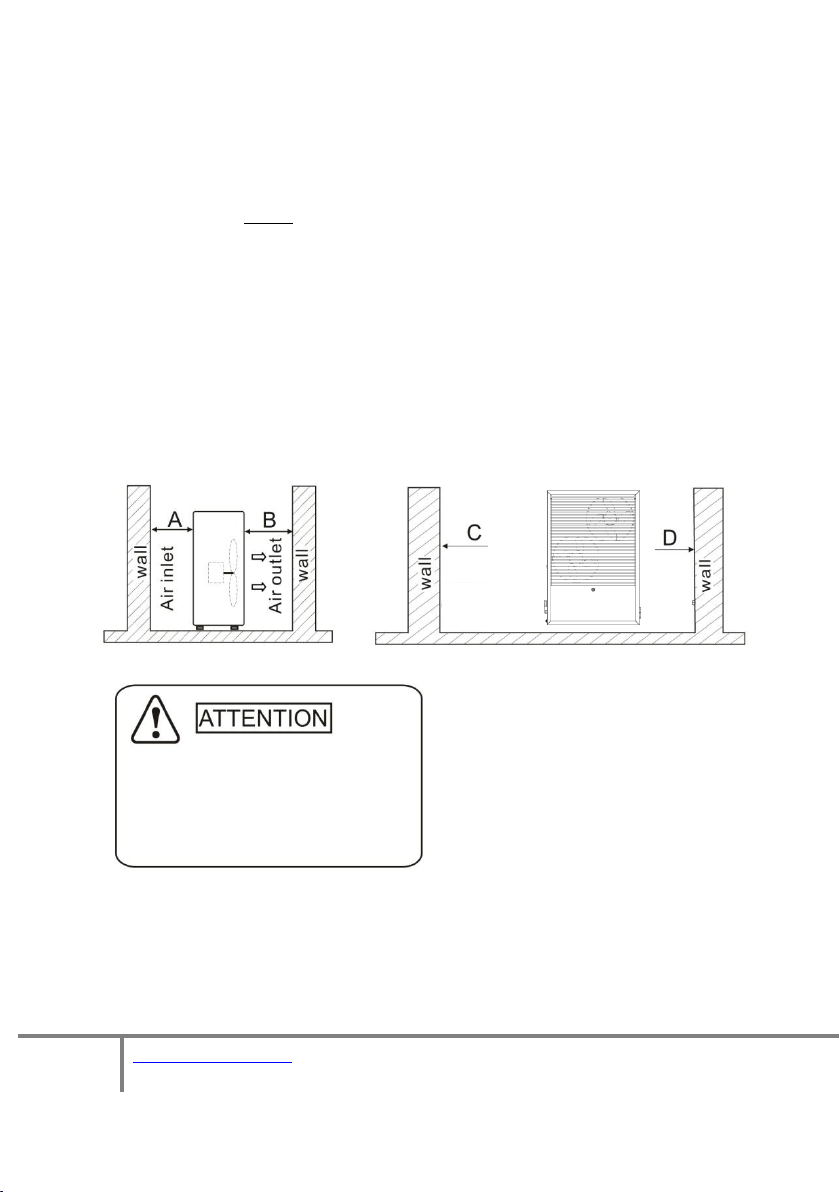
The unit must be sited away from any obstacles to the rear and
sides. There must be enough space around the unit for plumbing and
maintenance works as detailed in the diagram below. Care should
also be given to ensure that any overhead obstacles cannot create a
re-circulating air flow (where air exhausted from the ASHP is sucked
back in).
Further information is included in the section below entitled
Page 10
10 of 41
V 1.0
www.esavep.com PASRW060-D-BP
“Location of Unit”.
Clearances:
A. >500mm B. >1500mm
C. > 1000mm D. > 500mm
The unit generates condensate and this should be piped away
from the unit and into a suitable drain to prevent ice forming on the
area around the unit. This also applies to the water resulting from a
defrost cycle.
The unit MUST be firmly fixed to a secure base using the rubber
anti-vibration feet using suitable fixings. Failure to secure the unit
properly using the rubber feet will mean that it will fail MCS
Certification and cannot be registered on the MCS database.
To allow precipitation to run off the unit and to ensure that any
water entering the unit can drain through the holes in the bottom of
the unit, allow a 3mm fall left to right as you look at the fan.
5.2 Location of the Unit
5.3 Transporting the Unit
When lifting the unit during installation and transportation, an 8 meter strap
must be used and the unit protected by soft material placed between the
Page 11

11 of 41
V 1.0
www.esavep.com PASRW060-D-BP
lifting strap and the unit to prevent damage. (See picture below).
8m lifting web
Soft Protection
5.4 Plumbing Considerations
When planning the plumbing for the unit, please take the following into account:
Whenever possible, limit the number of bends in pipework.
The pipework must be clear and free from debris and blockages.
Pipework should be hot flushed before the unit is connected. Failure to
observe this precaution will invalidate the warranty.
Pipework must be pressure tested for leaks and this must be
carried before the unit is connected to avoid damage to the unit. Failure
to observe this precaution will invalidate the warranty.
It is highly recommended that a suitably sized buffer tank be
installed between the unit and the heating distribution system. Please
consult your installer or ESP when considering this system design
point – the right sized buffer tank can make a significant difference to
the economy and efficiency of the unit and the heating effectiveness.
6.0 Hydraulic Connection
6.1. Expansion vessels.
An expansion vessel must be installed where the heating system is unvented. The
size of the vessel(s) must be determined by the installer on site and take into
account the entire volume of water/glycol mix being heated including the volumes
contained in the Unit, the buffer tank, the distribution system, emitters and any
other system connected to the unit. For this reason, they are not included as part
of the optional ASHP installation pack. Expansion vessels can, however, be
provided by ESP as an additional optional extra.
6.2 Flow Switch
Page 12
12 of 41
V 1.0
www.esavep.com PASRW060-D-BP
The unit is fitted with a water flow switch that will pause the unit operation if
Transit Bung
water flow is not continuous (this includes where there is air in the system). The
flow switch is there to protect the unit and the setting should not be altered. If
the flow of water is insufficient, an error code will be displayed on the controller.
This will occur on initial start-up if the installer has failed to purge all the air from
the system.
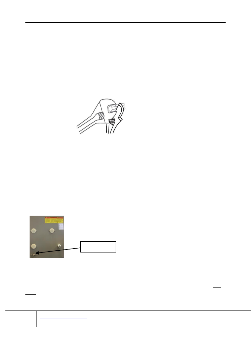
6.3 . Flexi Hoses
The final connection to the heat pump flow and return must be made with suitable
flexible pipes to prevent vibration in to the system pipework. Please ensure that
two wrenches are employed to take up the torque created in tightening the fittings
to avoid damage to both the fittings and the heat pump.
These flexible hoses are available from ESP as part of an optional ASHP Installation
Pack or individually.
6.4 Automatic bleed valves
Make sure that you fit automatic bleed valves (air vent)s at high points in the
system. The unit will shut down if air is in the system because the water flow
switch will recognize air in the system as no water flow and a system
alarm/protection code will appear on the unit controller.
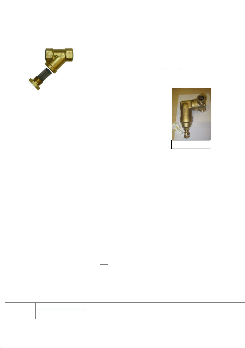
6.5 Transit Bung
The unit is supplied with a transit bung below the flow/return
pipes.
This bung must be removed and replaced with a drain-off- cock (DOC). There must
also be a DOC at any lower point in the system, to allow for effective drain-down of
the system as and when required. Please note that, if the system is to be left idle
for a long period in winter, the system should be drained down. You must fit full
flow lever valves on the flow and return to the unit so that the unit can be quickly
and effectively drained down where required for maintenance.
Page 13
13 of 41
V 1.0
www.esavep.com PASRW060-D-BP
Spirotrap Strainer
6.6 In-Line Filter
You must fit a Y-strainer in-line on the return pipe between
the buffer tank and the ASHP. This is normally fitted in an
external location and must have a full flow lever valve side
either side of the strainer to minimise glycol loss during
maintenance. Due to the mix of metals in the Varimax
it is both advisable and preferable to install a
Spirotrap ® rather than the minimum standard Y
strainer. Failure to fit a good quality strainer in the
return flow to the unit will invalidate the warranty on
the unit.
6.7 Flow Setter
ESP Strongly recommend the use of a flow setter in the return pipework from the
buffer to the ASHP. This will allow the system flow rate to be optimised for the
individual project.
6.8 TRVs
Where Thermostatic Radiator Valves (TRVs) are fitted to radiators in the system,
one should NOT be fitted to any radiator in the same room as a room thermostat.
6.9 Distribution Water Pump
If, as advised, you are using a buffer tank in the system, you will need to fit a
suitably sized water pump on the water distribution side of the system. This water
pump will need to be wired to receive an appropriate signal from the heating
system. Because the pump must be sized according to the requirements of the
distribution system, this item is not provided by ESP as part of any installation pack
but can be provided as an optional extra.
6.10 Glycol
The system must be protected from freezing by using a glycol solution in the water
circuits. The glycol/water should be added into the system from the expansion
Page 14

14 of 41
V 1.0
www.esavep.com PASRW060-D-BP
tank of the water loop or via the top of the buffer tank. The Glycol must be suitable
% Glycol
10
20
30
40
50
Ambient Temp
-3
-8
-14
-22
-33
Heating Capacity Fluctuation
.991
.982
.972
.961
.946
Power Input Fluctuation
.996
.992
.986
.976
.966
Water Flow Fluctuation
1.013
1.040
1.074
1.121
1.178
Water Drop Fluctuation
1.070
1.129
1.181
1.263
1.308
for the whole system which is why ESP can supply the ideal glycol for the Varimax
as an optional extra. The following table details the volume of the glycol/water
solution mix:
Note: if the glycol/water mix is too strong, the water flow and water pump
will be affected and the efficiency of the unit will be decreased. The above
table is for reference only and you should use a glycol/water solution that is
suited to local conditions. Using an incompatible Glycol may invalidate your
warranty.
7.0 Electrical Connection
7.1 Warning Notes
IMPORTANT! All electrical work MUST be carried out by a suitably qualified
electrician. It is not an exaggeration to say that, if you install/connect your unit to a
power supply and that installation/connection causes injury to, or death of
someone (even years after installation), you may be subject to prosecution under
the provisions of criminal law – some of the provisions carry very heavy custodial
sentences. IT IS NOT WORTHWHILE RUNNING THIS RISK.
PLEASE GET YOUR UNIT WIRED IN BY A PROFESSIONALLY QUALIFIED ELECTRICIAN
TO REMAIN SAFE AND COMPLY WITH THE LAW.
The remained of section 7 is intended as guidance for qualified electricians:
7.2 Before You Start
Before starting to wire in the power supply to the unit, please check that the power
supply is suitable for the unit (e.g. single phase, correct size cable, MCB etc. is
available) having taken into account the requirements of the entire site. All
electricity generating installations that are connected to the grid must be notified
to the Distributed Network Operator (DNO). The DNO requirements vary between
Page 15

15 of 41
V 1.0
www.esavep.com PASRW060-D-BP
the regions and details of the different Network Operators and you will need to
Typical Isolation Switch
follow the instruction of your local DNO. The unit power specification is stated on
a label on the side of the unit. We recommend the use of a dedicated 32 Amp Type
C or D MCB for connection of the power supply to the consumer unit.
7.3 MCB
The connection to the electrical consumer unit in the property must comply with
current electrical standards and Regulations and be done via a dedicated breaker
on the consumer unit that corresponds to the heat pump electrical capacity.
Failure to do this correctly can result in fire and/or permanent damage to the unit.
If the unit is not appropriately wired in to a suitable supply, the warranty on the
unit will be voided.
7.4 Isolation Switch
The heat pump MUST be connected to the power supply through a
two port rotary isolation switch that has at least a 3mm contact
separation at all poles, fixed in close proximity to the unit and
suitably positioned for general and emergency use as required by
relevant Regulations. The switch must NOT be attached to the unit
itself. The isolation switch must be suitable for the unit electrical
duty and comply with applicable Regulations.
7.5 Cable Routing
All wiring should be routed neatly, be kept as far away as possible from the units
water pipes and valves and comply with relevant Regulations. High voltage and low
voltage wiring should be clearly separated.
The maximum length of cable for the unit controller is 200 metres from the heat
pump and in order to get better signal quality over long distances, all the wires
should be twisted pair + Shield.
7.6 Wiring-in the Unit
The following points should be noted in relation to power supply wiring and system
components:
Remove the front louvred grill then remove the access panel to access
the electrical connection terminals.
Page 16

16 of 41
V 1.0
www.esavep.com PASRW060-D-BP
The control wire must be passed through the
Mains power
Connector Block
Controller
Connector
protective wire aperture in the unit casing and
plugged into the controller socket.
The power supply must go through the
protective wire aperture in the unit casing and
be connected securely to the terminals in the
control box. There is an alternate access
grommet in the casing near to the drain-off point.
In section 13 you will find wiring diagrams for the. Please refer to these
diagrams when introducing power or other wiring into the unit. You
should also use these diagrams to check the installation through before
starting the unit for the first time.
If the Building Regulations in your area require a 7-day programmer,
please note that the most efficient way of running an ASHP heating
system is to set the programmer to ALWAYS ON. A programmerthat
meet current building regulations may be used but it is very IMPORTANT
that any signal going back to the heat pump from the heating system
thermostat and/or programmer must be VOLT FREE ! The heating
system thermostat/ programmer controller is wired to terminals 45&46
inside the heat pump (these connections are not polarized) If you do not
use a volt free programmer you WILL damage the ASHP unit.
Page 17

17 of 41
V 1.0
www.esavep.com PASRW060-D-BP
Model Designation
PASRW060B-D-BP
Heating Capacity Range
Kw
6.0~15.0
BTU/h
20500~51000
Heating Power Input
Kw
1.6~7.0
Max. Running Power
Consumption
A
12.0/12.2
Power Supply
V/Ph/Hz
230/1/50
Number of Compressors
1
Compressor Type
Scroll
Number of Fans
2
Refrigerant
R410a
3.1kg
Compressor Oil
FV50S
1700cc
Fan Power Input
W
110 X 2
Fan Speed
RPM
850
Noise
dB(A)
59
Water Pump Power Input
Kw
.18
Max Water Head
M
12.5
Water Connection
Inch
1 1/4
Water Flow Volume
m3/h
2.5
Terminals 45/46
for volt free
connection
Mains power
Connection
Socket for
Wire
Controller
The unit MUST be connected to the master thermostat within the
building that controls the call for heat. If you do not have a master
thermostat connected to the unit from the building, you will not meet
Building Regulations.
8.0 Unit Specifications
Page 18

18 of 41
V 1.0
www.esavep.com PASRW060-D-BP
Water Pressure Drop
KPa
34
Water Capacity
Ltr
2.44
Unit Dimensions
mm
See Drawings
Unit Shipping
Dimensions
mm
1050 X 510 X 1475
Net Weight
Kg
See Unit Label
Shipping Weight
Kg
See Package Label
9.0 Commissioning
9.1 Pre-Start Checks
The following checks must be made prior to starting up the unit for the first
time:
Check that all relevant lever valves are open.
Check the water loop and expansion tank to ensure that both have
adequate water in them to allow the system to operate at 1 – 1.5
bar.
Ensure that all air has been purged from the system.
Ensure that pipes are well insulated using waterproof lagging, with at
least 30mm wall thickness.
Check the electrical wiring is correct in every respect. In particular,
make sure that the system is properly earthed.
Inspect the heat pump to ensure that all the cover screws have been
replaced and secured properly.
Check that the fan rotates freely.
When you switch on the power to the unit at the rotary isolation
switch, check the controller on the unit casing to see if there is an
error code being displayed.
9.2 Switching on the Unit
Please familiarise yourself with the unit controller and the
instructions in section 10 so that you can check various parameters as
the unit starts.
Start the heat pump by pressing the key on the unit controller
(see section 10). This will start the water pump. Check that the
water pump is running - there should be a reading of 0.2 MPa on the
Page 19

19 of 41
V 1.0
www.esavep.com PASRW060-D-BP
water pressure gauge.
When the water pump has been running for 1 minute, the
compressor will start up. Make sure that there are no strange noises
coming from it
immediately and check the compressor. If the
compressor runs well please check the pressure of the refrigerant.
Following the above, check whether the power input and running
current being drawn by the unit is in line with this manual. If not
please stop the unit and check for any problems.
If the unit is supplying a heating manifold, adjust the actuators on the
manifold(s) to balance the heating being received in all areas of the
system.
Check that the outlet water temperature is stable and increasing
smoothly towards the target temperature. The return water
temperature should move in line with the flow temperature with
around a 4 deg C. difference between the flow and return water
temperatures.
The parameters of the unit controller are factory set and you must
not change them without consulting your installer or ESP. The
exceptions to this are the running temperature (or flow temperature)
of the system and the time. However, changing the flow
temperature will affect the efficiency of your system and may affect
your ability to claim/continue to claim any Government grant.
Section 10 explains how to view the various parameters although the
default view will show the current status of the system.
. If the compressor sounds abnormal, stop the unit
Page 20

20 of 41
V 1.0
www.esavep.com PASRW060-D-BP
10.0 Unit Controller
Icon
Key
Meaning
Cooling Mode
Indicates that the unit is in cooling
mode.
Heating Mode
Indicates that the unit is in Heating
mode.
Boost Mode
Indicates that the unit is in Boosted
Heating mode.
Hot Water Mode
Indicates that the unit is in Hot Water
mode.
Number
Icon
Key
Function
①
On-Off
This is a multi-function button used to start the units, turn it
off, cancel a current operation and to return to the previous
menu page.
②
Time
Used to set the time and the optional timers.
③
Timers
Used to set the optional timers.
④
Check
To check current load (power) and temperatures.
⑤
Setting
Used to set various functions.
⑥
Up
Used to move ‘up’ in menus and to increase values.
⑦
Down
Used to move ‘down’ in menus and to decrease values.
⑧
Modes
Used to change between modes.
10.1 Main Interface
10.2 Basic operation
Page 21

21 of 41
V 1.0
www.esavep.com PASRW060-D-BP
Defrost Mode
Indicates that the unit is defrosting.
Inlet temperature
Indicates that the inlet temperature is
being displayed.
Outlet Temperature
Indicates that the outlet temperature is
being displayed.
Setting Mode
Indicates that the control is in setting
mode.
Value
Indicates that the basic display area is
displaying a parameter value.
Parameters
Indicates that the auxiliary display area
is displaying a parameter category.
Degrees Centigrade
Indicates that a value displayed in the
basic or auxiliary area is a temperature.
Kilowatts
Indicates that a value displayed in the
auxiliary area is a power value.
Hour
Indicates that the basic display area is
displaying an hour value.
Minute
Indicates that the basic display area is
displaying a minute value.
Second
Indicates that the basic display area is
displaying a second value.
Cubic Meters Per
Hour
Indicates that the basic display area is
displaying a flow rate.
Bars
Indicates that the basic display area is
displaying a pressure value.
Compressor
Indicates that the compressor is
running.
Pump
Indicates that the pump is running.
Fan
Indicates that the fans are running.
Lock
Indicates that the control pad is locked.
Fault
Indicates that a fault has been detected.
Start Time
The start time in timer mode (timer 2
illustrated)
Finish Time
The finish time in timer mode (timer 1
illustrated)
Page 22

22 of 41
V 1.0
www.esavep.com PASRW060-D-BP
10.3 Start-up and Shut Down
When the unit is in stand-by mode or has
automatically gone ‘blank’, the screen is
activated by pressing the on-off button.
When the unit is in stand-by mode, press the
on-off key and hold it for 0.5 seconds to start
the unit. When the unit is running, pressing
(and holding) the same button for the same
time will put the unit into stand-by mode.
When running, the display will show the inlet
temperature and the outlet temperature
NB. The screen will return to blank
automatically.
Page 23

23 of 41
V 1.0
www.esavep.com PASRW060-D-BP
10.4 Setting the target temperature
This symbol indicates that the unit is in heating mode
Press the up button once will show the
target temperature as set.
Symbol indicates that the target temperature can be set
Current Target Temperature
Pressing the up arrow will
increase the target
temperature, the down arrow
will decrease the target
temperature. Press the
key to save the setting or the
to cancel the change. If no
key is pressed within 20
seconds, the new setting will automatically be saved.
N.B. Your installer will have set the target temperature to
optimise the flow temperature for your building. Changing this
setting from the recommended temperature will decrease the
efficiency of your system. If you are considering changing this
setting from that set by your installer, you should consult your
installer or the ESP Technical Team first.
Page 24

24 of 41
V 1.0
www.esavep.com PASRW060-D-BP
10.5 Using the Premium User Interface
The Premium User Interface is used to change the time, set (or
change) timers, change from a Centigrade to a Fahrenheit
display, mute the interface and check the status of the ASHP.
Pressing the set button to
change to the Premium
User Interface. If the on-off
button is pressed or no
button is pressed within 20
seconds, the display will
revert to the start screen.
The Premium User Interface
has three additional buttons
on the left hand side of the
display.
Page 25

25 of 41
V 1.0
www.esavep.com PASRW060-D-BP
10.6 Setting the time:
Minute Segment
The display will change and
using the up and down buttons
will change the ‘hours’ setting.
Press the set key to save the
change.
First, press the time button.
Use the up and down
buttons to change the
‘minutes’ segment of the
clock. Press the set key to
save the change.
Page 26

26 of 41
V 1.0
www.esavep.com PASRW060-D-BP
Timer time
N.B. pressing the on-off button at any stage will cancel
the changes to that stage or not pressing a button within
20 seconds will save any changes made.
10.7 Setting the timers
The ASHP can be set to come on and go off again for two
periods per day. However, the most efficient way to run
an ASHP is to leave the unit running ‘always on’ and not to
set the timers.
Should you wish to set the timers against this advice, the
procedure is as follows:
Press and hold the time button for 2
seconds.
The display will change and the ‘on’
time of ‘timer 1’ can be set using
the up and down arrows to set the
hour. Press set to save the ‘hour’
and move to ‘minutes’. Us the up
and down arrows to set the minutes
then press set again to save the minutes. The display will
automatically move to ‘timer 1 off’. Use the same method
to set the desired ‘off’ time. At the end of that process, the
display will change to ‘timer 2 on’ and once that has been
set, ‘timer 2 off’.
Page 27

27 of 41
V 1.0
www.esavep.com PASRW060-D-BP
‘On 1’ time will flash
‘On 1’ time will stop flashing
Timer has been cancelled
10.8 Cancelling timers
To cancel a timer, enter the
Premium User Interface then
press the time button for 2
seconds. This will display the
current ‘Timer 1 on’ setting and
the time will flash. Press the
set button and the
Pressing the set button will
stop the time flashing.
Pressing the on-off button at
this stage will cancel the timer.
Press the on-off button once
more to return to the premium
user interface.
Page 28

28 of 41
V 1.0
www.esavep.com PASRW060-D-BP
Parameter Value
Parameter Number
10.9 Checking the Status of the ASHP
To Check the status of a
parameter, press the check
button whilst in the Premium
User Interface.
The display will change to
parameter 1. The
parameter value, the ‘val’
symbol, the parameter
number and ‘param’
symbols will be displayed.
Press the up and down
arrows to toggle through the
parameter list and the on-off
button to return to the
Premium User Interface.
The complete list of
parameters is in section 18
for information only;
changing any parameter other than the time/timers could
invalidate the warranty, the MCS registration and any
Government grants claimed.
Page 29

29 of 41
V 1.0
www.esavep.com PASRW060-D-BP
Indicates that the
display is locked
Fault Code
Serial
Number
Number of faults reported
10.10 Locking the Display
To lock the display, simply
press and hold the on/off
button for 5 seconds.
The ‘lock’ symbol will appear.
To unlock the display, press
and hold the on-off button for 5
seconds. However, the display
will automatically unlock if the
unit restarts after a power
failure or if a fault is reported.
10.11 Fault Displays
Should the ASHP develop a fault, a fault code will be
displayed in the following format:
The fault code will be
displayed, together with the
number of faults reported
and the serial number of the
fault. Use the up and down
arrows to scroll through
reported faults. A table of
fault and meanings is in
section 12.1.
Page 30

30 of 41
V 1.0
www.esavep.com PASRW060-D-BP
11 Maintenance
11.1 Essential Checks
Periodically clean the in-line filter (Y strainer or Spirotrap); this will need to be every
month for the first 6 months following start up of the system to allow installation
debris to be extracted. NOTE that a lack of water in the system or debris/dirt
entering the system can damage the unit.
11.2 Advisory Checks
Although there is no formal requirement for annual maintenance of the unit, the
following checks are strongly suggested:
Check the grill and evaporator for debris and remove before cleaning the evaporator.
Check the water supply and air vents frequently, to ensure that there is adequate
water within the system and that air is kept out of the system.
Check each part of the unit and the pressure within the system.
If any component has failed, replace it (and recharge refrigerant, if any has been
lost).
Check over the power supply and the electrical system generally to make sure that
no wires are lose or degrading. You must investigate any scorching visible or unusual
smells coming from the unit or the wiring.
Replace any part that may be malfunctioning; it is better to replace a part early (to
practice good preventative maintenance) than await failure.
If the heat pump is not to be used for a long period of time, please drain it down and
seal the unit to keep it safe for recharging and restarting when needed.
If a period of non use will include any possibility of the unit freezing, isolate the unit
and drain the water from the lowest point of the heat exchanger. Recharge the
water/glycol and carry out a full inspection of the unit before it is restarted.
The water loop of the heat pump MUST be protected from freezing in winter.
Please NOTE THE FOLLOWING – failure to observe the following requirements
WILL invalid the warranty for the heat pump.
Page 31

31 of 41
V 1.0
www.esavep.com PASRW060-D-BP
Please do not shut off the power supply to the heat pump in winter unless
Code
Malfunction
Reason
Resolution
P01
Inlet probe error
Short-circuit/Open-circuit
Check and change the
temp.
Sensor
P02
outlet probe error
Short-circuit/Open-circuit
Check and change
the
temp.
Sensor
P04
Ambient probe
error
Short-circuit/Open-circuit
Check and change the
temp.
Sensor
P07
Suct. temp. prb.
Error
Short-circuit/Open-circuit
Check and change
the
temp.
Sensor
P08
Disc. temp. prb.
Error
Short-circuit/Open-circuit
Check and change
the
temp.
Sensor
PP1
Disc. press prb.
Error
Short-circuit/Open-circuit
Check and change
the sensor
PP2
Suct. press prb.
error
Short-circuit/Open-circuit
Check and change
the sensor
E01
High pressure
High pressure switch off
Check cooling system
and pressure switch
E02
Low pressure
Low pressure switch off
Check cooling system
and pressure switch
E03
Flow switch alarm
No water or little
water
Check water flow and
water pump
E07
Freeze alarm
Inadequate water
Check water flow
and clear blockages
E19
Freeze alarm1
Low environment temp.
E29
Freeze alarm2
Low environment temp.
P181
High disc. temp
Overload of compressor
Check compressor
E21
Inv. Input
Lessvolt.
Low voltage leads the
overlarge current
Check the input
voltage
E22
Inv. Input
Overvolt
Input current over
protection current
Check input current
it is to be drained-down. When the air temperature is below 0°C, if the
inlet water temperature is above 2°C and below 4°c, the water pump will
start automatically once in every 72 hrs to provide frost protection.
12.0 Troubleshooting
12.1 Error Codes:
Page 32

32 of 41
V 1.0
www.esavep.com PASRW060-D-BP
E23
Input Over Cur.
War n
Input current over
protection current
Check input current
E24
Inv. DC
Overvoltage
DC bus voltage >DC
protection bus volt
Check bus
voltage
E25
Inv. DC
Lessvoltage
DC bus voltage<DC
protection bus volt
Check bus
voltage
E27
IPM Overcurrent
Overlarge current of the
IPM
Check current
E28
IPM Overheating
Over Temp. of the IP M
Module
Check current
E29
Inv. Temp. Probe
Fail
Short-circuit or ope n circuit
of sensor
Check and change
the sensor
E30
Inv. Input
Overvolt
Over Temp. of the parts
Lower the
temperature and
check
E31
Input Over Cur.
War n
Over Temp. of the parts
Lower the
temperature and
check
E32
IPM Sampling
Cur
Fault of current sampling
E33
Comp.
Overcurrent
Overlarge current of
compressor
Check the current
E34
Comp. Over Cur.
War n
Overlarge current of
compressor
Check the current
E35
Inv. Input Out
Phase
Lack of phase in input
voltage
Check the voltage
E36
Comp. Driver
Failure
Lack of phase or
breakdown of driver
Check the voltage
E37
Comm. Err DSPMCU
Fault of DSP or
communication board
Check
communication
connection
E38
Comm. Err DSPPFC
Fault of DSP and PFC
Check
communication
connection
E39
Inv. Sampling Volt
Fault of current sampling
Page 33

33 of 41
V 1.0
www.esavep.com PASRW060-D-BP
E40
EEPROM Error
Warn
Chip error
Check and change
the chip
E41
Weak Magnetic
Warn
Comm
Weak Magnetic
Problem
Possible Causes
Suggested Solutions
Heat pump will
not start
1 Incorrect power supply.
2 Power cable is loose.
3 MCB Tripped.
1 Shut off th e power and check power supply.
2 Check power cable is correctly connected.
3 Check for the cause an d reset MCB.
Water pump is
running but
noisy or without
water
1 Lack of water in the pipes.
2 Air in pipes.
3 Isolation water valves closed.
4 Blocked water filter
1 Check the water supply and fill pipes.
2 Bleed the system.
3 Open the valves.
4 Clean the water filter.
The compressor
runs
continuously or
the output is
low
1 Refrigerant leaking.
2 Inadequate insulation on ASHP flow and
return pipes.
3 Low heat exchange rate on air side
Exchanger.
4 lack of water flow
1 check for the gas leakage an d recharge the refrigerant.
2 make good insulation on water pipe.
3 clean the ai r side heat exchanger.
4 clean the water filter.
High
compressor
exhaust
1 System refrigerant overcharged.
2 Low heat exchange rate on air side
exchanger
1 Reduce refrigerant.
2 Clean the air side heat exchanger.
Low pressure
problem
of the system
1 Insufficient refrigerant.
2 Blocked filter or capillary.
3 Low water flow.
1 Check for refrigerant leaks and recharge.
2 Replace filter or capillary.
3 Clean the water filter and bleed the system.
Compressor will
not run
1 Power supply failure
2 Compressor contactor broken
3 Power cable loose
4 Protection on compressor has tripped
5 Incorrect return water temp setting.
6 Low water flow.
1 Check power supply;
2 Replace compressor contactor;
3 Tighten the power cable;
4 Check the compressor exhaust temp.
5 Reset the return water temp.
6 Clean the water filter and bleed the system.
Compressor
unusually noisy
1 Liquid refrigerant getting into
Compressor.
2 Compressor failure.
1 Check the cause of poor evaporation an d clear fault.
2 Replace compressor.
Fan does not run
1 Fan relay failure.
2 F an motor failure.
1 Replace th e fan relay;
2 Replace fan motor.
The compressor
runs but heat
pump has no
heating or
cooling capacity
1 No refrigerant in the heat pump.
2 Heat exchanger failure.
3 Compressor failure.
1 Check for leaks, cure the fault and recharge refrigerant.
2 Investigate the cause and replace the heat exchanger;
3 Replace compressor.
Low outlet water
temperature
1 Low water flow rate.
2 Low target temperature set.
1 Clean the water filter and bleed the system.
2 Check the target temperature setting and reset if
necessary.
Low water flow
reported
1 Lack of water in the system;
2 Flow switch failure.
1 Clean the water filter and bleed the system.
2 Replace th e flow switch.
12.2 Simple Faultfinding
The following is a list of some basic faults and solutions.
Page 34

34 of 41
V 1.0
www.esavep.com PASRW060-D-BP
13.0 Wiring Diagram
For zero volt connection
from Controller
Page 35

35 of 41
V 1.0
www.esavep.com PASRW060-D-BP
14.0 Guarantee
14.1 Guarantee Terms
Should any factory fitted Temperature and/or Pressure Relief Valve(s) or
other safety devices be tampered with or removed or any recommended
Temperature or Pressure Relief Valves/safety devices not be fitted, your
warranty/guarantee will be invalidated. Neither the Distributor nor
Manufacturer shall be responsible for any damage resulting from the
tampering, howsoever caused, save where such exclusion is unlawful.
ESP warrants/guarantees the electrical parts, thermal controls and valves
relating to the cylinder for a period of one year from the date of purchase, with
the exception of normal wear and tear including any damage damage caused as a result
of lime scale deposits.
The stainless steel vessel forming part of the cylinder is
warranted/guaranteed for a period of five years against faulty manufacture
or materials provided that:
i) It has been properly installed by a competent installer as per the
instructions and recommendations contained in this manual and all relevant
codes of Practice and Regulations in force at the time of installation.
ii) It has not been modified in any way other than by ESP.
iii) It has only been used for the storage of wholesome water.
iv) It has not been installed in a location liable to be subjected to frost, nor ha
s it been tampered with or been subject to misuse or neglect.
v) No factory fitted parts have been removed for unauthorised repair or repla
cement.
Page 36

36 of 41
V 1.0
www.esavep.com PASRW060-D-BP
vi) Within 45 days of purchase the user completes and returns the
registration certificate.
The compressor in the heat pump is warranted/guaranteed for 2 years
from the date of purchase. Remaining parts of the heat pump are
warranted/ guaranteed for 1 year from the date of purchase.
Evidence of purchase and date of supply must be submitted with any
warranty/guarantee claim.
This warranty/guarantee is not valid for installations outside the United
Kingdom or the Republic of Ireland.
Any warranty/guarantee is for replacement parts only.
The purchaser of the unit acknowledges that he/she has seen ESP’s conditions of
supply and has understood them.
All of our units are RoHS approved units.
This guarantee does not affect your statutory rights.
15.0 Environmental Information
This product is made from many recyclable materials, therefore at the end of
its useful life, it should be disposed of at a Local Authority Recycling Centre
in order to realise the full environmental benefits. The R410a gas contained in the unit
should be reclaimed, recycled or destroyed, in accordance with current Government
regulations covering F-Gas available from WWW.Gov.UK and should only be attempted
by a qualified technician. For disposal of the glycol added to the system, the glycol
supplier should be contacted. For ESP glycol, the disposal instructions are supplied with
the non-toxic glycol sold by ESP.
Please note:
The pace of product development is such that we reserve the right to
change product specifications without notice. We do, however, strive to
ensure that all information in this leaflet is accurate at the time of
publication.
Page 37

37 of 41
V 1.0
www.esavep.com PASRW060-D-BP
The Varimax 20 has built-in weather compensation to ensure that that maximum
efficiency is maintained and that output is matched to the load of the building and
the external ambient temperature. With factory defaults set (it is unwise and,
possibly, dangerous to change these – see warning in section 10.9) the compensation
is as follows:
16.0 Weather Compensation
Page 38

38 of 41
V 1.0
www.esavep.com PASRW060-D-BP
Frequency (HZ)
Frequency (HZ)
Frequency (HZ)
17.0 Performance
Page 39

39 of 41
V 1.0
www.esavep.com PASRW060-D-BP
Frequency (HZ)
Frequency (HZ)
Frequency (HZ)
Page 40

40 of 41
V 1.0
www.esavep.com PASRW060-D-BP
Parameter
Number
Description
Default
Value
Units
A01
High Pressure protection delay
0
Secs
A01
Low Pressure protection delay
300
Secs
A03
Outlet water antifreeze
5
°C
A04
Return differential antifreeze
2
°C
A05
Exhaust temperature maximum
105
°C
A06
Frequency reduction of exhaust overtemp
10
Hz
A07
Frequency reduction cycle for exhaust overtemp
60
Secs
A08
Return differential of exhaust over temp
25
°C
C01
Compressor on-delay
180
Secs
C02
Compressor off-delay
120
Secs
C04
Minimum compressor frequency
30
Hz
C05
Maximum compressor frequency
90
Hz
D01
Defrost start trigger pressure
5.0
bar
D02
Defrost end trigger pressure
27
bar
D03
Defrost cycle
45
mins
D04
Defrost maximum
8
mins
D05
4-way valve switching delay
55
Secs
D06
Slide defrosting set on
1
(logic)
D07
Slide defrosting trigger temp
2
°C
D08
Ambient temp defrosting trigger
17
°C
D09
Pressure differential for defrost
2.7
bar
E01
Manual mode for EEV set on
0
(logic)
E02
Overtemp protection for EEV (Heating)
1
°C
E03
Overtemp protection for EEV (Cooling)
0.5
°C
E04
Opening of EEV Valve during heating
250
Steps
E05
Opening of EEV Valve during cooling
250
Steps
E06
Opeinging of EEV Valve during defrost
450
Steps
F01
Max fan speed trigger (Cooling)
27
bar
F02
Min fan speed trigger (Cooling)
15
bar
F03
Max fan speed trigger (Heating)
4
bar
F04
Min fan speed trigger (Heating)
3
bar
F05
Air valve voltage min
3 V F06
Air valve voltage max
10 V F07
Pressure differential fan trigger (Cooling)
3
bar
F08
Pressure differential fan trigger (Heating)
2
bar
F09
Rated rotate speed
6.5 V H01
Power-off memory set on
1
(logic)
18.0 Parameter List:
Please note that the changing any one of the parameters in this list may:
1. Be dangerous.
2. Invalidate the warranty on the unit.
3. Invalidate the MCS registration (where applicable).
4. Invalidate any Government grant claimed for the installation.
Page 41

41 of 41
V 1.0
www.esavep.com PASRW060-D-BP
H02
4-way valve on when heating set
1
(logic)
H03
Oil return for compressor set
1
(logic)
H04
Frequency protection on compressor overtemp set
1
(logic)
P01
Water pump intermittent set
1
(logic)
P02
Water pump interval
30
mins
P03
Water Pump duration
2
mins
P04
Compressor delay after water pump start
1
mins
P05
Target temp differential (Heating)
1
°C
P06
Target temp differential (Cooling)
1
°C
R01
Target set temp (Cooling)
12
°C
R02
Target set temp (Heating)
40
°C
R03
Trigger differential for electric heater
2
°C
R04
Use electric heater set
0
(logic)
R05
Ambient temp electric heater start
9
°C
R06
Electric heater delay
30
mins
You are strongly recommended to contact the ESP technical
support team before changing any of these parameters.
CONTACT DETAILS
Earth Save Products Technical Team – 01865 598158
 Loading...