

Page 1

Part
Number:
10060-001
Rev:
03
Description:
SSS-903 TG-E
Install Guide
Date:
08/15/2017
Page: 1 of 53
Date
Revision
Description
Approved
3/21/13
02
Addition; Appendix II
Warranty & Return Policy
A. Burgos
Revision History
Information and technical data disclosed in this document
may be used and distributed only for the purposes and to
the extent specifically authorized by ESP Safety Inc.
ESP Safety Inc. Reserves the right to change published
specifications and designs without prior notice
OPERATING MANUAL
SSS-903 Toxic Gas Detection System
Model SSS-903 Transmitter and Controller
Model PGU-IR Infrared Optical Gas Sensor
Model PGU-P Photo Ionization Gas Sensor
Model PGU-E Electrochemical Gas Sensor
Model PGU-C Catalytic Bead Gas Sensor
Page 2

Part
Number:
10060-001
Rev:
03
Description:
SSS-903 TG-E
Install Guide
Date:
08/15/2017
Page: 2 of 53
General Information .............................................................................................................. 3
Specifications of SSS-903 with PGU Sensors ........................................................................ 4
SSS-903 Theory of Operation .............................................................................................. 11
Data Communication ........................................................................................................... 17
IMPORTANT SAFETY INFORMATION................................................................................... 18
Physical Installation Procedure .......................................................................................... 19
Physical Installation Quick Guide........................................................................................ 20
Wiring Requirements .......................................................................................................... 24
Power up and Stand Alone Operation of the SSS-903 ........................................................ 31
RS-485 Modbus Digital Communication and Operation ...................................................... 32
Calibration Procedures ........................................................................................................ 33
Non-Invasive Calibration Magnet Procedure ...................................................................... 33
Non-Invasive Calibration Procedure with HART Communicator……………………………..….33
Bench Test Calibration Procedure with ESP Commander ................................................. 438
Unpacking A New SSS-903 .................................................................................................. 44
Appendix 1 Explosion Proof Design……………………………………………… .............. …………45
Appendix 2 Warranty & Return Policy .............. ……………………………………………………46
Page 3

Part
Number:
10060-001
Rev:
03
Description:
SSS-903 TG-E
Install Guide
Date:
08/15/2017
Page: 3 of 53
This instruction guide details the specification, application and operation of the ESP Safety Inc. SSS-903 with an included
sensor. The SSS-903 System consists of two components, a receiver and gas specific sensor that have been factory
configured and calibrated to provide detection of toxic, flammable and combustible gases in open or closed environments. The product
includes multiple features required to report alarms when the toxic gas concentrations in the environment
reach three independently programmed levels. Each alarm also triggers a relay that is provided as a standard feature,
which can be used to operate warning devices, sirens, valves or switches.
The SSS-903 receiver is a versatile product that can be used in a specific proximity or in a decoupled mode with the sensor
and receiver head located up to 500 feet apart. Furthermore, any SSS-903 can be reconfigured in the field to detect toxic
gases using optional sensor replacements.
The SSS-903 system is recommended for applications that require a gas detector with localized digital readout of detected
gas levels. It comes factory standard for with Analog 4-20mA output with embedded HART, an independent HART connector
that is conveniently located on the SSS-903 enclosure able, relay contacts, and Modbus RS485. The system is comprised of an
SSS-903 Receiver and plug-in universal PGU sensors for electrochemical (PGU-E) , infrared (PGU-IR) ,photo-ionized (PGU-P) and
catalytic bead (PGU-C)detection. Power is supplied from an external 24 VDC nominal power source (source can range 18-3VDC). In
operation the
SSS-903 system has been designed for operation in temperature ranges from minus 40 to 75 °С (without internal heated option
activation) and minus 60 to 75 °С (with activated internal heated option) and relative humidity of up to 100 % (non-condensing)
The SSS-903 receiver includes 5 LED annunciators plus an easily readable LCD display. On the display an operator can determine
information of alarm status, gas detected, current level detected and view a Time Weighted Average (TWA) run time graphic
showing each event and level detected during a user programmed time from 3 to 30 minutes. The design of the SSS-903 is an
approved product for use in control monitoring of gas contamination levels with flammable and toxic gases present in the
working area environment of oil, gas and chemical industries All electronics are enclosed in explosion-proof aluminum or
stainless steel housings that have been certified by FM-Approvals for use in explosive areas pertinent to classes 1 and 2 with the
potential hazard of forming explosive gas mixtures attributed to the subgroup IIС and to explosion hazard categories Т1–Т6,
inclusive of the following zones, premises and facilities:
Drilling and production platforms
Refineries
Bulk terminals and tank farms
Compressor stations
Pipelines
Transportation facilities
Petrochemical facilities
Paint Manufacturing
Fertilizer plants
Fuel loading facilities
Residential areas
Boiler stations
Non-invasive calibrations can be performed in the field using an included magnetic wand or a HART communicator.
A device descriptor file is available from ESP Safety for use with a HART communicator. Calibration can also be performed with an
included Windows PC application, ESP Commander. Both HART and ESP Commander applications can supply real time output of
current operational data plus access a non-volatile memory in the SSS-903 for further diagnostic analysis.
General Information
Applications
Page 4

Part
Number:
10060-001
Rev:
03
Description:
SSS-903 TG-E
Install Guide
Date:
08/15/2017
Page: 4 of 53
Electrical Characteristics
Operational Characteristics
Mechanical Characteristics
Input Voltage
+24VDC Nominal (+18 to 32VDC)
Power Consumption
2 W-standby
5 W-during alarms
Output From SSS-903
+4-20mA industry standard analog with embedded HART
Digital RS-485 Modbus RTU
HART interface with easy access dedicated connector
4 “Dry Contact” relays (NO/Form-A)
All Relays Contact Rating 1Amp@125VAC/30VDC
Alarm Relays
3 User Programmed Alarm Relays
1 Fault Condition Relay
GT Sensor Interface to SSS903 Receiver
Digital RS-485 Modbus RTU
*Note All ESP Safety gas detector products can be interfaced with the SSS-903
Sensor Types / Model
Electrochemical: PGU-E
Infrared: PGU-IR
Photo Ionized: PGU-P
Humidity Range
Up to 100%, non-condensing
(Withstands up to 100% RH for short periods)
Operating Temperature
Standard Operation: -40oF to +167oF (-40oC to +75oC)
With Optic Heater Enabled: –76oF to +167oF (-60oC to +75oC)
Ingress Protection
IP66
RFI/EMI Protection
EN50081-1 / Class B E> 50270
*Operates with no interference from a 5 watt walkie talkie keyed (transmitting) at 1 meter
Annunciators (LED)
Tri-color status LED indicates operational mode, fault, and gas presence.
Three LED indicators for Alarms activation
A fourth LED indicates the unit is in calibration mode
Displayed Information
(Illuminated LCD Display)
Continuous sensor data
Gas Type
Measuring Units
Three Fixed Alarm Thresholds
Graphic display of trending data for Peak Readings and Time-Weighted Average (TWA) of gas
concentration 3-30 minutes
Explosion Proof Labels for SSS903 & PGU Sensors
Ex d [ia Ga] IIC T6 Gb
Ex d ia IIC T6
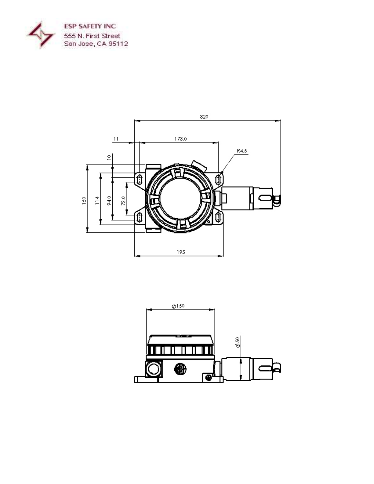
Dimensions of SSS-903
Receiver
270x150x120mm
10.63”x5.9”x4.73”
Dimensions of PGU Sensors
94x50mm
3.7”x1.97”
SSS-903 and PGU
Stainless Steel Grade-316
Cable Entry
2 Cable Entries ¾” NPT
Weight
5.5kg / 11lbs
Specifications of SSS-903 with PGU Sensors
Page 5
Part
Number:
10060-001
Rev:
03
Description:
SSS-903 TG-E
Install Guide
Date:
08/15/2017
Page: 5 of 53
Dimensions Diagram of SSS-903 Receiver
All dimensions are in mm
Page 6

Part
Number:
10060-001
Rev:
03
Description:
SSS-903 TG-E
Install Guide
Date:
08/15/2017
Page: 6 of 53
Table 1: SSS-903 with PGU-E Electrochemical Gas Sensor Range, Accuracy and
Response Times
Using Gas Specific Electrochemical Detectors
*Response Time is the time to reach a percentage of final reading when gas concentration is equal to full scale of the sensor
range of detection. (i.e. T50=50% 0f Range)
**Some sensors have multiple ranges one of which is determined by the user during setup or calibration
Gas Formula
Range of Detection**
Accuracy
Response Time*
Hydrogen
(H2)
0 to 4 % vol (100%
LEL)
±2% full scale
T50 < 40 seconds
Т90 < 60 seconds
0 - 1% vol (0 - 100)
ppm
Carbon Monoxide
(CO)
(0 - 100) ppm
±2% full scale
T20 < 10 seconds
Т90 < 25 seconds
(0 - 500) ppm
(0 – 1000)ppm
Ammonia
(NH3)
(0 - 1000) ppm
±2% full scale
Т90 < 90 seconds
Hydrogen Fluoride
(HF)
(0 - 10) ppm
±2% full scale
T50 < 30 seconds
Т90 < 90 seconds
Methanol
(CH3OH)
(0 – 100)ppm
± 2% full scale
Т90 < 90 seconds
Oxygen
(O2)
(0 - 30) % vol
±2% full scale
Т90 < 11 seconds
Hydrogen Sulfide
(H2S)
(0 - 20) ppm
±2% full scale
T20 < 10 seconds
T50 < 12 seconds
Т90 < 25 seconds
(0 - 50) ppm
(0 - 100) ppm
Chlorine
(CI2)
(0 - 20) ppm
±2% full scale
Т90 < 25 seconds
Formaldehyde
(CH2O)
(0 - 10) ppm
± 2% full scale
Т50 < 20 seconds
Nitrogen Dioxide
(NO2)
(0 - 20) ppm
±2% full scale
T50 < 12 seconds
Т90 < 25 seconds
Sulfur Dioxide
(SO2)
(0 - 20) ppm
±2% full scale
T50 < 12 seconds
Т90 < 25 seconds
(0 - 100) ppm
Hydrogen Chloride
(HCI)
(0 - 30) ppm
±2% full scale
T50 < 30 seconds
Т90 < 90 seconds
Vinyl Acetate
(C4H6O2)
(0 - 100)ppm
± 2% full scale
Т90 < 90 seconds
Page 7

Part
Number:
10060-001
Rev:
03
Description:
SSS-903 TG-E
Install Guide
Date:
08/15/2017
Page: 7 of 53
Using Gas Specific Photoionized Detectors
*Response Time is the time to reach a percentage of final reading when gas concentration is equal to full scale of the sensor
range of detection. (i.e. T50=50% 0f Range)
**Some sensors have multiple ranges one of which is determined by the user during setup or calibration
Note: All gases with ionization potential <10.6 eV
Gas
Formula
Range of
Detection**
Accuracy
Response Time*
Benzene
C6H6
(0 - 100) ppm
± 2% full scale
± 2% full scale
Т50 < 9 seconds
Т90 <25 seconds
Т90 <25 seconds
(0 - 1000) ppm
(0-10000) ppm
Ethylene
C2H4
(0 - 20) ppm
(0 - 2000) ppm
Isobutylene
C4H8
(0 - 20) ppm
(0 - 200) ppm
(0 - 2000) ppm
Methyl Mercaptan
СH3SH
(0 - 100) ppm
Other ranges per
request
Table 2: SSS-903 with PGU-P Photo Ionization Gas Sensor:
Range, Accuracy and Response Times
Page 8

Part
Number:
10060-001
Rev:
03
Description:
SSS-903 TG-E
Install Guide
Date:
08/15/2017
Page: 8 of 53
Using Gas Specific IR Detectors
*Response Time is the time to reach a percentage of final reading when gas concentration is equal to full scale of the sensor
range of detection. (i.e. T50=50% 0f Range)
Gas
Formula
Range of
Detection**
Accuracy
Response Time*
Methane
CН4
(0 -100) % LEL
± 3% to 50% LEL
± 5% from 51%
to 100% LEL
T20 < 5 seconds
Т90 < 25 seconds
Propane
C3Н8
Ethylene
C2Н8
Hexane
C6Н14
Butane
С4H10
Isobutane
l-С4Р10
Ethanol
C2H5OH
Cyclopentane
C5H10
Propylene
C3H6
Methanol
CH3OH
Gasoline Vapor
Diesel Vapor
JP4 Fuel Vapor
Carbon Dioxide
CO2
(0 to 2) % Vol
(0 to 5 ) % vol
( 1 – 3000) ppm
± 2% full scale
Т90 <25 seconds
Table 3: SSS-903 with PGU-IR Infrared Optical Detection:
Range Accuracy and Response Times
Page 9

Part
Number:
10060-001
Rev:
03
Description:
SSS-903 TG-E
Install Guide
Date:
08/15/2017
Page: 9 of 53
Using Catalytic Bead (pellisor) sensor specifically for detection of hydrogen
*Response Time is the time to reach a percentage of final reading when gas concentration is equal to full scale of the sensor
range of detection. (i.e. T50=50% 0f Range)
** All data refers to catalytic bead sensor as tested with H2 gas from an approved source. The sensor data listed is based on ideal test
environment with no interference from other gases
Gas
Formula
Range of
Detection**
Accuracy
Response Time*
Hydrogen
H2
0-100 % LEL
< ± 10% of
measured value
T 90 < 10 seconds
Table 4: SSS-903 with PGU-C Catalytic Bead Sensor:
Range Accuracy and Response Times
Page 10

Part
Number:
10060-001
Rev:
03
Description:
SSS-903 TG-E
Install Guide
Date:
08/15/2017
Page: 10 of 53
CE 0539 II 2 G
Ex d[ia] IIC T4 (Tamb 75°C)
IP 66
Ex d [ia] IIC T4
(Tamb 75°C)
IP 66
1 Ex d [ia] IIC T4 X T= -60°C....75°C
IP 66
EN Standards
EN 60079-0: 2006
EN 60079-1: 2007
EN 61779-1: 2000
EN 60529: 1991+A1: 2000
EN 50270: 2006.
94/9/EC ATEX:
IECEx:
Certifications
Page 11
Part
Number:
10060-001
Rev:
03
Description:
SSS-903 TG-E
Install Guide
Date:
08/15/2017
Page: 11 of 53
The SSS-903 is physically designed to perform in a wide range of hazardous environments and harsh weather conditions.
Employing a durable enclosure that can withstand these conditions and even explosion is key to the operation and function
of the device.
The SSS-903 is an elegant design that uses only two printed circuit board assemblies (PCBA) that have also been designed to
resist the effects of environmental challenges. The PCBAs are installed in a layered fashion with a single interconnection for easy
removal.
The Controller PCBA provides all information to the user via LED and LCD display. A micro controller with embedded software
performs all functions used in communication and control. As noted the controller card also functions as the driver for the
LCD display and performs all calculations used for the timed graphic HART. Event information displayed on the graphic cHART
is also stored in a Non-Volatile memory within the PGU sensor that can be accessed using ModBus or a HART communicator.
The second module is the Power PCBA. This PCBA accepts and regulates the externally supplied power source in addition to
all signal connections. Four solid state-sealed relays are also located on the Power PCBA eliminating the potential of electronic
discharge associated with mechanical relays.
All signals enter and exit the enclosure via ¾” threaded female attachments for conduit as required by the user application
and local regulations.
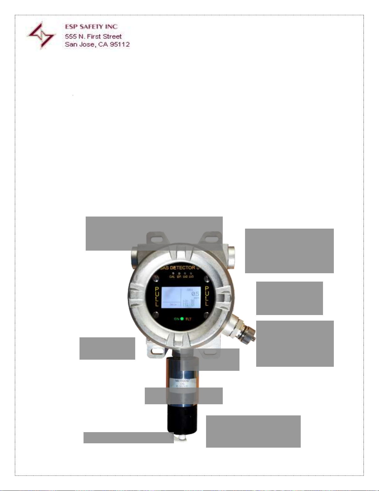
¾ Inch Inlet/Outlet Receptacles
For Explosion Proof Conduit and
Cabling
Dedicated HART Device
Communication Connector
with Protective Cover
Installed
.35” Diameter Surface
Mount (Left and Right)
Screw On Explosion Prove Housing Cover with
Shatter Proof Glass Window
Physical Earth
Ground Clamp
Housing Cover Lock
Screw
Removable PGU Sensor
Splash Guard and Gas Collector
Removable Detector Module Housing
cover with Lock Screw
SSS-903 Receiver Operation
Figure 1 SSS-903 Receiver with PGU Sensor Installed
Page 12
Part
Number:
10060-001
Rev:
03
Description:
SSS-903 TG-E
Install Guide
Date:
08/15/2017
Page: 12 of 53
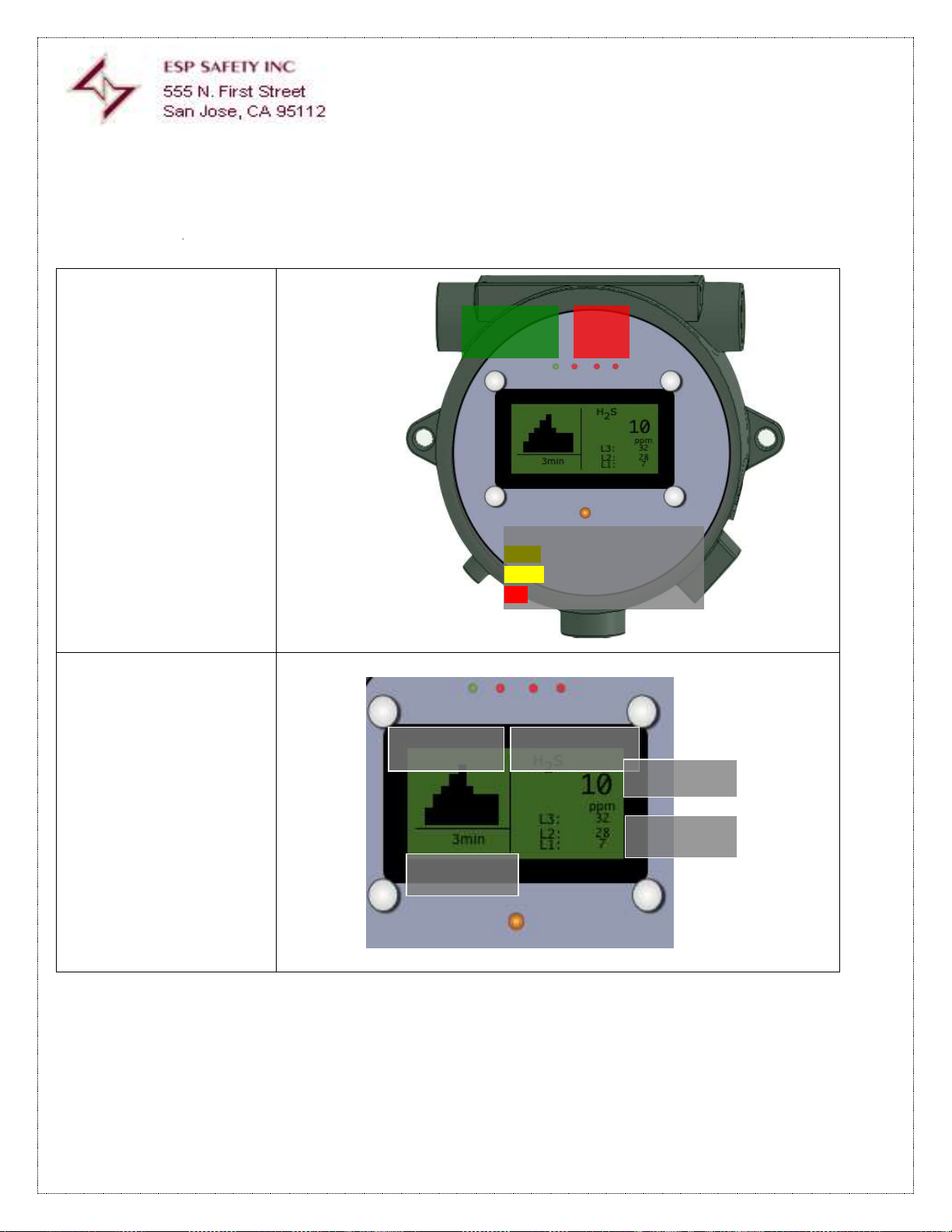
Figure 2- SSS-903 LED
Indicators
Figure 3 -
SSS-903 LCD Display
Detected Gas
Current Value
Alarm Preset
Values
Time Value of
Graphic Display
Graphic Display
Green
Calibration
Mode
Red
Alarm
1 2 3
Operational Status
Green – Normal Operation
Yellow – Alarm Active
Red – Fault Condition
Page 13
Part
Number:
10060-001
Rev:
03
Description:
SSS-903 TG-E
Install Guide
Date:
08/15/2017
Page: 13 of 53
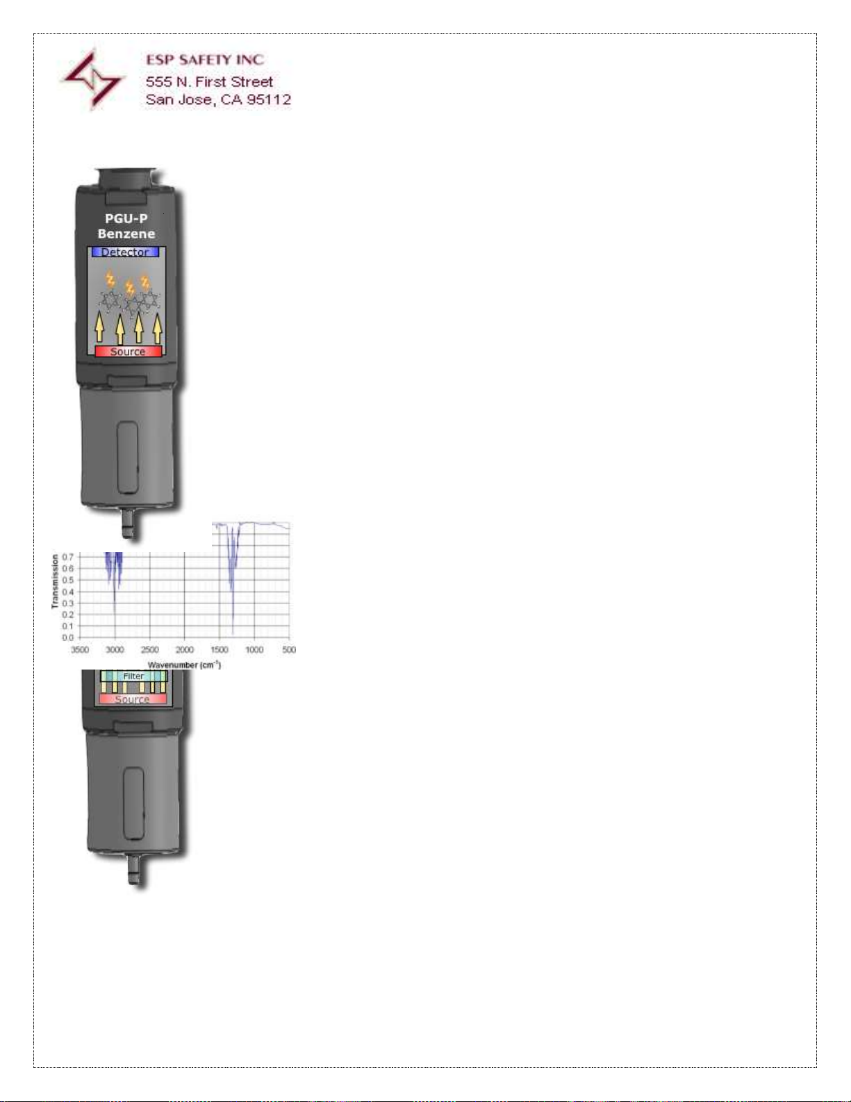
The PGU-P performs selective detection of hydrocarbon molecules using infrared light and
photo ionization detectors (PID). Air containing molecules of the selected combustible gas
passes into a collection chamber that has an IR source and detector. The molecules containing
the combustible gas absorb the IR photons and become ionized. Ionized molecules create an
electric current that is measured by the detector. The electric current increases as the amount
of gas molecules in the chamber increases. The current is measured and processed by the
PGU-P sensor, generating the signals that are passed to the SSS-903 receiver via RS-485. Each
detector is factor programmed for the gas requested by the customer at the time of purchase.
Operation the PGU-IR is based on selective signal disruption by hydrocarbon molecules when an
infrared light source is projected to an optical detector. Measurement for a specific gas is
determined by passing the IR energy through a filter placed between the source and a chamber
where the gas is collected. If nogas is present, the detector will receive all of the energy
radiated by the IR source and generating an electrical current. When gas molecules enter the
collection chamber, each molecule of the gas blocks the IR energy reducing the output of the
detector, which is then processed by the PGU-IR sensor. Each detector is delivered preset for a
specific gas, in the example shown, the gas is Methane (CH4), which ionizes at two points on the
light spectrum, one for each Atomic Element, and are measured as wave numbers (cm-1).
Figure -5 TG-IR Detector
PGU-P Photo Ionization Gas Sensor Theory of Operation
Figure-4 PGU-P Detector
PGU-IR Infrared Optical Gas SensorTheory of
Operation
Page 14
Part
Number:
10060-001
Rev:
03
Description:
SSS-903 TG-E
Install Guide
Date:
08/15/2017
Page: 14 of 53
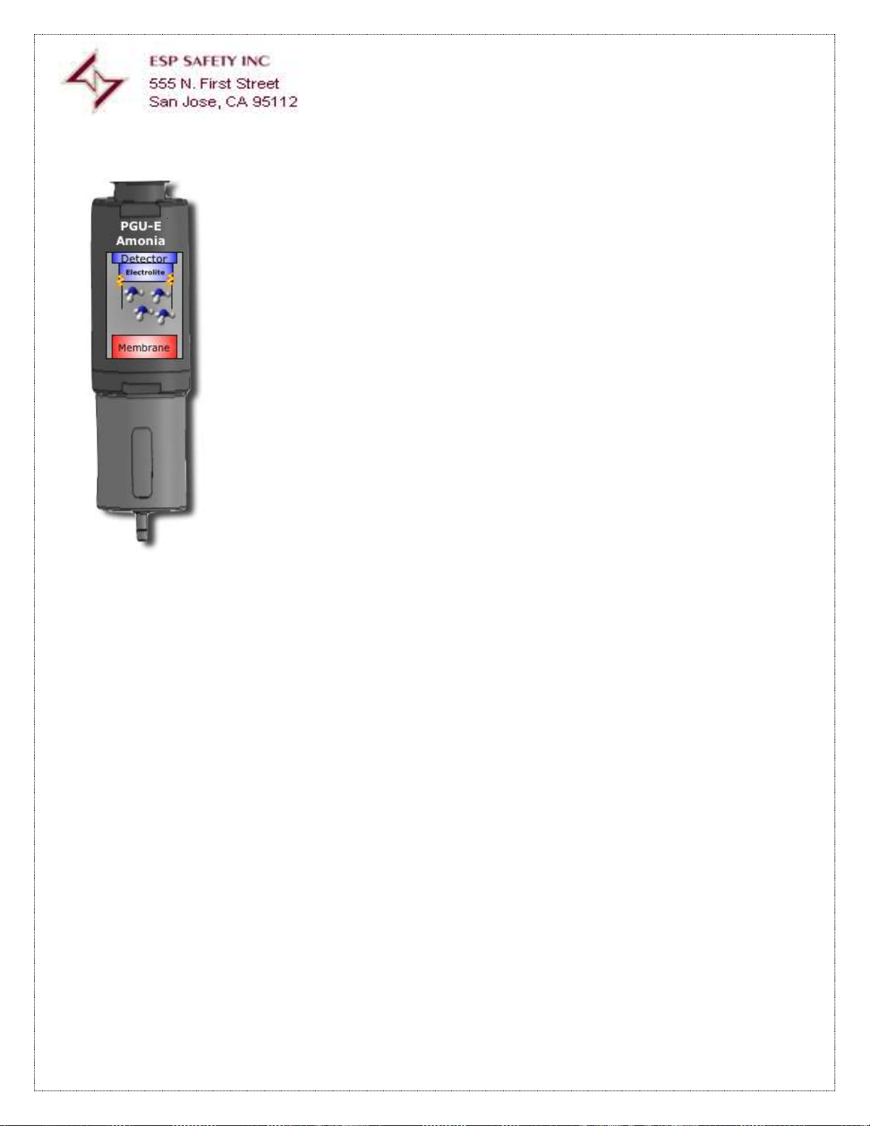
The PGU-P sensor contains electrode in contact with an electrolyte. The target gas
diffuses into the sensor through a membrane and comes into contact with electrodes
where it is oxidized. The electrochemical reaction results in an electric current that passes
to PGE-P microcontroller and from there to the SSS-903 receiver. The magnitude of the
current is controlled by how much of the target gas is oxidized by the electrode. Output
current from the sensor is also linearly proportional to the gas concentration. A linear
output allows for more precise measurement of low concentrations and much simpler
calibration.
Figure6 – TG-E Detector
PGU-E Electrochemical Gas Sensor Theory of Operation
Page 15
Part
Number:
10060-001
Rev:
03
Description:
SSS-903 TG-E
Install Guide
Date:
08/15/2017
Page: 15 of 53
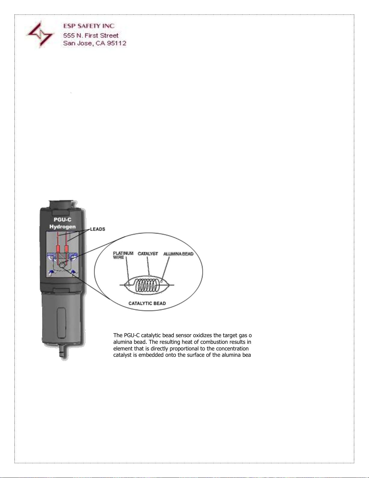
The PGU-C catalytic bead sensor oxidizes the target gas on the surface of a heated
alumina bead. The resulting heat of combustion results in a change in resistivity of the
element that is directly proportional to the concentration of the gas. A precious metal
catalyst is embedded onto the surface of the alumina bead to lower the oxidation
temperature. Two platinum wire leads are embedded in the alumina bead and connected
electrically in a Wheatstone bridge circuit. Heat is generated by passing current through
the leads.
Figure7 – TG-C Detector
PGU-C Catalytic Bead Gas Sensor Theory of Operation
Page 16

Part
Number:
10060-001
Rev:
03
Description:
SSS-903 TG-E
Install Guide
Date:
08/15/2017
Page: 16 of 53
Field Replaceable Detector
Module
Housing Label Must
Match with Detector
Gas.
Removable Housing
Cover with Filter
Each PGU sensor consists of PGU module with imbedded processing and a single gas specific plug-in
electrochemical, infrared (optical) or photo-ionized detector. There is a filter located between the
collection chamber and the detector to minimize potential contamination from dust or moisture. The
collection chamber is covered by a splashguard, which also serves as the gas collector. The
splashguard also has an inlet nipple for calibration purposes.
Each PGU detector internally stores the data reported to the SSS-903, HART, or Modbus. All
calibration information is also stored in the PGU module processor, thus any PGU module can be
moved to another SSS-903 receiver and resume data collection from the time of removal.
The detector module may be replaced in the field with a one that is intended for use to detect the
same gas. If a different gas is required a replacement PGU module must be ordered from ESP Safety
or their representative. Aside from detector or filter replacement there are no user serviceable parts
in the PGU sensor.
Figure 7 – PGU Detector Module
Page 17

Part
Number:
10060-001
Rev:
03
Description:
SSS-903 TG-E
Install Guide
Date:
08/15/2017
Page: 17 of 53
The SSS-903 provides three digital communication methods:
HART (Highway Addressable Remote Transducer) accessible via a dedicated connector that is located on the SSS-903 housing.
Digital RS-485 ModBus-RTU (Remote Terminal Unit)
HART over +4 to 20 mA output
HART is a bi-directional communication protocol that provides data access between
Intelligent field instruments and host systems. In most applications for the
SSS-903 the host is an ESP-Safety specific software application available from
the HART Foundation for use on a technician's hand-held HART communicator
device.A HART system in considered non-invasive in that the SSS-903 does not
have to be opened or removed from a field installed location.
HART communicators and RS-485 devices can access:
Information detected gas type
The measuring range in PPM or LEL%
Value of current gas concentration
State and programming of fixed alarm thresholds
Calibration Zero Cal Address of the SSS-903 as used by RS-485
Download of Non-Volatile Memory of event occurrence from a 60 day history
Modbus is an interface structure that is used for communication to control devices (PLC) or computers. Modbus is a similar
to HART but has been adapted as the industry standard for communication to multiple devices with a single cable run.
(Series or “Daisy Chain” connection) Unlike HART, RS-485 must be considered and designed into the installation of the SSS-903.
All of the same functions available with HART can also be accessed remotely with this system.
Modbus is available for use as a dedicated communication system with High Speed data communication.
ESP-Safety provides a Windows compatible computer application, ESP Commander, that provides all access to the
SSS-903 functions, and is often used for bench calibration of units removed from the field or prior to new installations.
ESP-Commander may require a customer provided translation device. All ESP Safety gas detector models have the ability
to interface with ESP Commander in RS-485 “daisy chain” networked installations. Modbus is also available in a single
point to point interface (one SSS-903 to One port of a control system as a data signal
that is imbedded in the +4 to 20mA analog output. In this application the data rate is significantly slower at 1200kb/s.
ESP-Safety has an available rack mounted control system that can
be used with all ESP devices along with those of other manufacturers.
Explosion proof integrity of SSS-903 units installed and in operation it is must not be modified in any form. All labeling must be
intact and visible. All surfaces that are subject to disassembly or removal during installation or maintenance must be installed as
detailed in Appendix I (Explosion Proof Diagram)
Emerson 475 Shown
Figure 8 - SSS-903 with
HART Communicator
Figure 9 - UPES Controller
Digital Data Communication
HART Dedicated Connector
Digital RS-485 Modbus
UPES Controller
Explosion Proof Integrity
Page 18

Part
Number:
10060-001
Rev:
03
Description:
SSS-903 TG-E
Install Guide
Date:
08/15/2017
Page: 18 of 53
Caution: The installation of SSS-903 must comply with relevant requirements of the latest edition
of the national Electri Code (ANSI/NFPA 70)
Caution: Connection Conduit, Barrier Glands, and Epoxy Sealants are to meet
EN-50018/IEC 60079-1 Standards
Caution: ESP Safety Inc. Recommends use of shielded cable with 14AWG conductors reaching a span
no greater than 3,900 ft. (1200 meter)
Be sure to read and understand the entire instruction manual before installing or operating the gas detection system. The products
described in this document can be used with a variety of ESP-Safety gas detector models to provide earlywarning of the presence of a
toxic or explosive gas mixture. Proper device installation, operation, and maintenance is required to ensure safe and effective
operation. If this equipment is used in a manner not specified in this manual, safety protection may be impaired.
Caution: The installation of SSS-903 must comply with relevant requirements of the latest edition of the national
Electric Code (ANSI/NFPA 70)
Caution: Connection Conduit, Barrier Glands, and Epoxy Sealants are to meet EN-50018/IEC
60079-1 Standards
Caution: ESP Safety Inc. Recommends use of shielded cable with 14AWG conductors reaching a span no greater
than 3,900 ft. (1200 meter)
Cautions and Warnings
This user guide includes numerous cautions and warnings that are specifically included to prevent injury to
personnel and prevent damage to equipment. Care is also taken to include notation of all applicable
standards and best practices as appropriate information that may apply to any use or procedure associated
with the product.
WARNING: TOXIC, COMBUSTIBLE, AND FLAMMABLE GASES OR VAPORS ARE VERY
DANGEROUS. USE EXTREME CAUTION WHEN THESE HAZARDS ARE PRESENT.
WARNING: Take appropriate precautions, including wearing and use of protective clothing and
devices when servicing the SSS-903 as they may have remnants of corrosive solutions.
IMPORTANT SAFETY INFORMATION
Page 19

Part
Number:
10060-001
Rev:
03
Description:
SSS-903 TG-E
Install Guide
Date:
08/15/2017
Page: 19 of 53
Physical Installation Procedure
Preparing For
Installation
The SSS-903 has unique installation procedures for either local or remote hardware
configurations. Before installation, evaluate the gas leak locations and other
conditions at the test site and configure the unit for that particular need.
PGU sensor Location
Selection of PGU sensor location is critical to the overall performance of the product.
Five factors play an important role in the selection of PGU sensor locations:
Density of the gas to be detected
Most probable leak sources within the industrial process
Ventilation and prevailing wind conditions
Personnel exposure
Maintenance access
*Note the PGU Sensor must be pointed down.
Density of detected
gas
If the target gas is heavier than air, the sensor should be located within 4 feet of
grade. Heavier than air gases will tend to settle in low-lying areas. For gases lighter
than air, PGU sensor placement should be 4-8 feet above grade in open areas or in
pitched areas of enclosed spaces.
Probable leak
sources
Leak sources include flanges, valves, and tubing. Connections of the sealed type
where seals may either fail or wear. All potential leak sources and SSS-903 mounting
locations are best determined by facility engineers with experience in similar
processes.
Ventilation and
Prevailing Winds
Normal ventilation or prevailing wind conditions can dictate efficient location of gas
PGU sensors so that migration of potential gas clouds is quickly detected.
Personnel exposure
If an undetected migration of gas clouds should approach concentrated personnel
areas such as control rooms, maintenance or warehouse buildings. Selection of PGU
sensor location should include the potential leak source and perimeter of personnel.
Use of ESP Safety PGUAES open field detectors should be considered for these areas.
Maintenance Access
Consideration should be given to providing easy access for maintenance personnel.
PGU sensor location should also take into account the proximity to contaminants that
may foul the PGU sensor prematurely.
SSS-903 Receiver
and PGU Sensor
Location Guidelines
There are no standard rules for placement since the optimum PGU sensor location is
unique for each application. Before installing the SSS-903, check the conditions at the
installation site to make a placement determination. The following guidelines can
assist in determining the best possible placement of the SSS-903:
Locate the SSS-903 near potential gas leak sources and away from excessive heat,
light, wind, dust, water, vibration, shock, and radio frequency interference (RFI).
Ensure the installation location has sufficient space to accommodate the SSS-903
housing, PGU sensor, and all necessary cabling.
Mount the SSS-903 with the PGU sensor pointing down.
Mount the SSS-903 housing in an easily accessible location for reading the digital
display and calibration checks
Page 20

Part
Number:
10060-001
Rev:
03
Description:
SSS-903 TG-E
Install Guide
Date:
08/15/2017
Page: 20 of 53
Physical Installation Quick Guide
Page 21

Part
Number:
10060-001
Rev:
03
Description:
SSS-903 TG-E
Install Guide
Date:
08/15/2017
Page: 21 of 53
Tools Required
18-Inch Adjustable Crescent (Spanner Wrench) with 2-inch or greater span for installation
and removal of PGU sensor/Sensors
2-MM “Flat Head” screwdriver for protective cover lock screw and wire terminal block clamps
#2 Phillips Head Screwdriver for Ground Connector
Physical
Installation/
mounting
The SSS-903 can be physically mounted in a number of ways.
The surface mount “ears” can be used for a wall mount.
Figure 10 – Mounting To Pole (Local Configuration)
Figure 11- Mounting
with PGU Sensor in
local configuration
Local configuration refers to the
configuration where the SSS-903 housing
and the pre-calibrated PGU PGU sensor
are attached and placed in the same
location. This is also commonly referred
to as a stand-alone configuration.
Install explosion proof conduit or cable or
conveying appropriate cabling using into a ¾” Male NPT fitting using an explosion proof
cable gland.
Mount the SSS-903 vertically with the Smart PGU sensor pointing down to reduce the
possibility of dirt and dust building up on the window.
Ensure that the open slots of the gas passage are straight up and down to enable the gas to
rise up and through the PGU sensor’s cell.
Using the two surface mounting holes, attach the SSS-903 to a pole bracket or a surface
mount to a wall.
Caution: The SSS-903 with TG Sensor installed must
always be installed in a vertical orientation with the TG
Sensor pointing down. This will minimize collection of
contaminates in the TG sensor.
Page 22

Part
Number:
10060-001
Rev:
03
Description:
SSS-903 TG-E
Install Guide
Date:
08/15/2017
Page: 22 of 53
Mounting in
Remote
configuration
Figure 13 –
Sensor removal
In addition to the standard local configuration, the SSS-903 also supports remote placement
of the PGU sensor up to 500 feet away from the housing.
Mount the SSS-903 housing vertically to reduce the possibility of dirt and dust building up on
the window.
Using an optional bracket or the two surface mounting holes, attach the SSS-903 to a stable
surface or wall.
Mount the PGU sensor to a stable surface or wall with user supplied clamps.
Connect the explosion proof conduit or cable to the SSS-903 housing.
Connect the explosion proof conduit or cable to the PGU sensor.
Ensure that the PGU sensor is pointing down for maximum exposure.
All connections require explosion proof and sealed cable glands.
FIGURE 12 - REMOTE CONFIGURATION
Note: The SSS-903 remote configuration option can be utilized with any gas analyzer
equipped with the standard RS-485 (Modbus RTU) output and a power consumption of 24
VDC. This includes all of ESP Safety’s toxic gas PGU sensors and ESP’s SGOES Combustible
Gas Detector.
Earth Grounding
The enclosure of the SSS-903 Reciever must be
earthed/grounded for for electrical safety and to limit the
effects of radio frequency interference. An earth/ground
point is provided on the outside of the SSS-903 Explosion
Proof enclosure
Use 14 AWG copper, (Stranded or Solid), wire.
Loosen the screw sufficiently to enable wrapping the wire
around the screw in a “U” shape. Raise the flat and lock
washers and place the wire between the flat washer and
ground base.
Tighten the screw to10.4lb-in torque.
Figure 14 – Ground
Page 23

Part
Number:
10060-001
Rev:
03
Description:
SSS-903 TG-E
Install Guide
Date:
08/15/2017
Page: 23 of 53
Step 1- Remove
Protective Cover
Figure 15 - Cover Removal
Loosen the Protective Cover Lock Screw
approx. one turn.
Remove the explosion proof protective
cover by
turning counter
clockwise. The handle
of a Crescent or
Spanner Wrench can
be used as a lever
with the cover removal tabs.
Step 2- Remove
Control PCBA
Module
Figure 16 - Remove Module
Un-plug the control circuit by grasping two of the
thumbscrews surrounding the display and pulling outwards.
Step 3- Wire
Preparation
Figure 17 –Wire
Prep
Use a stripping tool for the selected wire gauge to remove ¼-inch
(6mm) of the insulating jacket for each conductor to be inserted in the
terminal blocks of the Connector PCBA.
Step 4- Electrical
Connections
Figure 18 - Spring Clamp Terminal Block
Use a 2MM Flathead screwdriver or Spring Actuation Tool to
engage spring connector slots when installing or removing
wires.
Step 5-
Re-assemble the
SSS-903
After wiring is completed insert the control module with the 4 LED lights at the top then
attach the Explosion Proof protective cover onto the SSS-903 and secure by tightening the
housing cover lock screw.
Paladin Model GripP – 1117
Multi-gauge wire stripper
shown above
¼” (6mm)
Shielded 14 AWG Stranded wire
(Recommended)
6mm Insulated Crimp On Ferrule
ESP safety recommends a Ferrule
that is crimped onto the wire for
better connectivity and ease of
insertion into the terminal block.
Insert wire
Use tool to lever the
spring open
Remove
Cover
Lock
Screw
Removal
Page 24

Part
Number:
10060-001
Rev:
03
Description:
SSS-903 TG-E
Install Guide
Date:
08/15/2017
Page: 24 of 53
Caution: All cable/conduit entries must be sealed with an appropriate and certified sealing plug and cable gland. The use of
industrial grade, armored field cable is recommended. If installing the PGU sensor in a hazardous area using remote
configuration, armored cabling is required for the Probe/Sensor connection to the SSS-903 receiver.
Cabling Guidelines
If installing connection cables in an explosion proof conduit, do not use the same conduit to carry wiring for any other purpose
or equipment.
If installing the PGU sensor in a hazardous area using remote configuration armored cabling is required for the PGU Sensor
connection to the SSS-903 Receiver
Minimum 14 AWG (2.08 mm2) shielded cable conductors are required for optimal performance. The gauge of the wire used
determines the maximum distance between the controller and the PGU SENSOR.
When using Modbus power and signal must be separate shielded twisted pair conductors
CAUTION: System Power / Digital Ground
System ground must be provided at the point
of origination for 24VDC. Failure to do this
may result in loss of range and/or signal
integrity.
General Wiring Requirements
Page 25

Part
Number:
10060-001
Rev:
03
Description:
SSS-903 TG-E
Install Guide
Date:
08/15/2017
Page: 25 of 53
Terminal Block X-3
Terminal Block X-1
Terminal Block X-2
Terminal Block X-4
J1
Figure 19 - Power Board Connecting Terminal Block Locations
Page 26

Part
Number:
10060-001
Rev:
03
Description:
SSS-903 TG-E
Install Guide
Date:
08/15/2017
Page: 26 of 53
Connection
Label
Function
Terminal Block X1
SCR
Not Used
RS485B
ModBus RTU Interface
RS485A
ModBus RTU Interface
GND
Digital Ground
+24V
+24 VDC Power (From External Source)
Terminal Block X2
SCR
Bridge from X1 SCR for Daisy Chain configuration
RS485B
Bridge from X1 RS-485B for Daisy Chain configuration
RS485A
Bridge from X1 RS-485A for Daisy Chain configuration
GND
Bridge from X1 GND
+24V
Bridge from X1 +24 VDC
Terminal Block X3
+4 to 20 mA
Analog status system with embedded HART
communication data
GND
Digital Ground
Fault Relay In
Normally Open Relay closes when the SS-903 detects
a fault condition.
Fault Relay Out
Closed condition output of Fault Relay
Level 1 Relay In
Normally Open Relay closes when the SS-903 detects
a pre-programmed level condition determined by +4
to 20 mA.
Level 1 Relay Out
Closed condition output of Level 1 Relay
Level 2 Relay In
Normally Open Relay closes when the SS-903 detects
a pre-programmed level condition determined by +4
to 20 mA.
Level 2 Relay Out
Closed condition output of Level 1 Relay
Level 3 Relay In
Normally Open Relay closes when the SS-903 detects
a pre-programmed level condition determined by +4
to 20 mA.
Level 3 Relay Out
Closed condition output of Level 1 Relay
Terminal Block X4
SCR
RS-485B
Probe
RS-485a
GND
+24V
Jumper 1
J1
Termination Jumper For “Daisy Chain” RS-485
configuration of Multiple SSS-903 Units.
Table 6 SSS-903 Connections
Page 27

Part
Number:
10060-001
Rev:
03
Description:
SSS-903 TG-E
Install Guide
Date:
08/15/2017
Page: 27 of 53
Installation Wiring
There are several methods of wiring connections for the SSS-903 Receiver. To accommodate this variety and provide ease of
installation, the SSS-903 includes all hardware and connections for any configuration determined by the user making it well suited for
new and replacement applications.
Caution: The installation of SSS-903 must comply with relevant requirements of the latest edition of the national
Electric Code (ANSI/NFPA 70)
Caution: Connection Conduit, Barrier Glands, and Epoxy Sealants are to meet EN-50018/IEC
60079-1 Standards
Caution: ESP Safety Inc. Recommends use of shielded cable with 14AWG conductors reaching a span no greater
than 3,900 ft. (1200 meter)
Caution: All cable/conduit entries must be sealed with an appropriate and certified sealing plug and
cable gland. The use of industrial grade, armored field cable is recommended. If installing the TG
sensor in a hazardous area using remote configuration, armored cabling is required for the Sensor
connection to the SSS-903 receiver.
Remote PGU Sensor Wiring to SSS-903
Figure 20 –PGU Connection to Terminal Block X-4
Page 28

Part
Number:
10060-001
Rev:
03
Description:
SSS-903 TG-E
Install Guide
Date:
08/15/2017
Page: 28 of 53
Figure 21 - Comprehensive Wiring Diagram for Multiple use Configuration
Page 29

Part
Number:
10060-001
Rev:
03
Description:
SSS-903 TG-E
Install Guide
Date:
08/15/2017
Page: 29 of 53
Figure 22 - Connecting the SSS-903 to ESP Safety UPES Multichannel Controller
Figure 23 - Connecting the SSS-903 Using 3 Wire Analog Interface Method
Page 30

Part
Number:
10060-001
Rev:
03
Description:
SSS-903 TG-E
Install Guide
Date:
08/15/2017
Page: 30 of 53
Figure 24 - Connecting the SSS-903 Using 4 Wire Analog Interface Method
Page 31

Part
Number:
10060-001
Rev:
03
Description:
SSS-903 TG-E
Install Guide
Date:
08/15/2017
Page: 31 of 53
Installation
Review Prior to
Startup
Once the mounting, cabling, and alarm relay installation has been completed, the SSS903 is ready to begin the power-on sequence.
Before applying power to the system for the first time, review the steps below:
Verify that the SSS-903 has been properly mounted. Ensure that all conduit / cable
gland entries have been tightened and sealed if necessary.
Verify that all of the signal wires have been installed correctly.
Verify connection or earth/ground to the enclosure.
Verify connections between the SSS-903 housing and the PGU sensor if in remote
configuration.
Verify the connections between the SSS-903 housing and any control room devices and
alarm systems.
Make sure that the SSS-903 cover is securely installed and locked with the housing
cover lock screw.
Make sure to turn off or disconnect any external devices, such as Trip Amplifiers, PLC
devices or DCS systems, until after the startup sequence has been completed.
Once you are ready to begin startup, verify that the power supply is connected properly
and verify input voltage with the SSS-903 disconnected at the source. The SSS-903 is
powered by 24 VDC (12 to 36 VDC voltage range).
After completing the above, the SSS-903 is ready to be powered on.
Startup Procedure
Before the initial power up,
remove power from or
disconnect all output devices
and alarms to prevent actuation.
Apply power to the
system. Upon first
power-up, the SSS-903
should be allowed to
stabilize and allow the
sensor to initialize
Figure 25 - Initialization Screen
After 15 seconds, the
Operational Status indicator
diode will glow green and all
information will be available on
the display.
Figure 26 - Operation Screen
Power up and Stand Alone Operation of the SSS-903
Page 32

Part
Number:
10060-001
Rev:
03
Description:
SSS-903 TG-E
Install Guide
Date:
08/15/2017
Page: 32 of 53
The Modbus interface is used for communication to all ESP Safety Detector models. Up to 480 devices can be connected in
a Daisy Chain method. Modbus® RTU protocol uses ASCII/Hex data for communication and allows all SSS-903 functions to be
transmitted using this method.Modbus protocol is a Master-Slaves protocol. ESP-Safety provides a communication program,
ESP Commander that uses a PC as a Master Device
controlling all connected Detectors as Slave devices.
The ESP Commander master initiates all communication to the devices. The slave detectors
cannot transmit data without receiving a request
from the master. The slave detectors cannot communicate with each other.
MODBUS® is a registered trademark of Schneider
Automation Inc.ESP Commander can perform real
time monitoring, control operations, adjustment of
function, and download of the non-volatile flash
memory on the SSS-903.
ESP Safety manufactures a variety of detection devices for fire, explosive and toxic gas detection. Up to eight detectors, of any
mix, can be connected in a string, or daisy chain. When using this configuration, Jumper J-1 must be used for the last unit in
the chain, providing signal termination. All other units must have J1 removed.
RS-485 Modbus Digital Communication and Operation
Figure 27 - Modbus Connection with Analog and Alarm
RS-485 Modbus Daisy Chain Digital Data Loop
Figure 28 - Modbus Daisy Chain
Page 33

Part
Number:
10060-001
Rev:
03
Description:
SSS-903 TG-E
Install Guide
Date:
08/15/2017
Page: 33 of 53
There are three methods available to perform calibration of the SSS-903 with Smart Probe:
Using RS-485 Modbus with the ESPCommander control Program (Bench Test Method A)
Using a HART Communicator (Non-invasive In Field or Bench Test Method B) HART Communicator required
Using a Magnetic “Wand” (Non-invasive In Field or Bench Test Method C) No Instrument or tools required
Non-Invasive Zero set up can be performed on SSS-903 detectors when installed in the permanent
location by using a magnetic Wand that is included with every SSS-903 unit.
Required Equipment For
Non-Invasive
Calibration
.
¼” PVC Tubing
ESP Safety Zero Gas and Span
Gas disposable canister for
the appropriate gas.
ESP Safety Magnetic Wands
Figure 29 - Equipment for Magnetic Wand Calibration
Magnetic Wand
Warning: Trained staff must perform all calibration procedures.
The calibration procedure work area must be located a safe distance from any hazardous zone.
Follow all site safety operating procedures before removing any detector from service.
Warning: All alarms must be disconnected to eliminate the possibility of erroneous alarm
activation when performing this procedure.
Calibration Procedures
Methods of Performing Calibration
Page 34

Part
Number:
10060-001
Rev:
03
Description:
SSS-903 TG-E
Install Guide
Date:
08/15/2017
Page: 34 of 53
Non-Invasive Magnetic Wand Calibration Procedure
Page 35

Part
Number:
10060-001
Rev:
03
Description:
SSS-903 TG-E
Install Guide
Date:
08/15/2017
Page: 35 of 53
Purging
The working area must be
free of any Gas or
contaminants.
Connect the nipple of Sensor’s
collection chamber to the Zero
Gas Cylinder with PVC tubing.
1. Apply magnetic wand to
SSS-903 calibration point.
CAL LED will turn solid
green and ‘CALIBRATION’
message is displayed
2. Apply zero gas for at least
1 minute at 0.3 LPM flow
rate. Ensure reading
displayed on SSS-903 is a
stable value (should be
zero).
Figure 30 – Purge for Wand Calibration
Wand Zero Cal
Apply magnetic wand to
SSS-903 calibration point.
CAL LED will start to flash
green. Displayed value
should be zero (zero
calibration is now
complete).
Figure 31 - Zero Cal with Wand
Page 36

Part
Number:
10060-001
Rev:
03
Description:
SSS-903 TG-E
Install Guide
Date:
08/15/2017
Page: 36 of 53
Wand Span Cal
1. Apply calibration gas for 1
minute at 0.3 LPM flow
rate. Reading displayed
should increase to near
calibration gas value.
Ensure reading is stable
value.
2. Apply magnetic wand to
SSS-903 calibration point.
The CAL LED will start
rapidly flashing green.
The magnetic calibration
gas value is now set,
displayed value should
equal magnetic
calibration gas value.
3. Remove the calibration
cup, once calibration gas
is clear of the sensor
(readings approach zero)
CAL LED will turn off and
‘CALIBRATION’ message
turns off indicating
calibration is complete.
Figure 32 – Span Cal with Wand
Caution: Factory calibration of the PGU sensor is performed using a gas flow rate of 0.3 LPM
(Litres Per Minute). ESP Safety recommends that field calibration of PGU sensors is performed at
the same flow rate. Using non-recommended flow rates may result in calibration errors.
Page 37

Part
Number:
10060-001
Rev:
03
Description:
SSS-903 TG-E
Install Guide
Date:
08/15/2017
Page: 37 of 53
Non-Invasive field calibration can be performed on SSS-903 detectors with a HART communicator.
Establish communication between the HART Communicator and
the SSS-903 by attaching the ESP Safety-supplied cable to the
HART connection port of the SSS-903
Zero Calibration using a HART Communicator
Step 1:
From the Online Display, select 1 Device Setup
Step 2:
Highlight and select the 2 Detailed Setup item.
Figure x-xx: Device Setup
Figure x-xx: Online Display
Non-Invasive Calibration Procedure w HART Communicator
Page 38

Part
Number:
10060-001
Rev:
03
Description:
SSS-903 TG-E
Install Guide
Date:
08/15/2017
Page: 38 of 53
Page 39

Part
Number:
10060-001
Rev:
03
Description:
SSS-903 TG-E
Install Guide
Date:
08/15/2017
Page: 39 of 53
Step 3:
Highlight and select the 6 Sensor Trim item.
Step 4:
From the Sensor Trim Display, highlight and select 3
Zero Trim
Warning Message 1:
Note the warning message. As a safety precaution,
any alarms or devices controlled by the gas sensor
output should be disabled at this time.
Warning Message 2:
Note the warning message. The user may abort the
calibration sequence at this point if calibration is not
desired at this time.
Step 5:
Apply the zero gas to the sensor and wait for the
reading to stabilize. Press “OK” to complete the
sensor zero calibration. Press “ABORT” to cancel the
calibration sequence. Remove the zero gas from the
sensor.
Warning Message 3:
Figure x-xx: Warning Message 2
Figure x-xx: Warning Message
Figure x-xx: Sensor Trim Select
Figure x-xx: Detailed Setup
Figure X-XX: Sensor Zero Calibration
Figure x-xx: Warning Message
Page 40

Part
Number:
10060-001
Rev:
03
Description:
SSS-903 TG-E
Install Guide
Date:
08/15/2017
Page: 40 of 53
Span Calibration using a HART Communicator
Step 1:
From the Online Display, select 1 Device Setup
Step 2:
Highlight and select the 2 Detailed Setup item.
Step 3:
Highlight and select the 6 Sensor Trim item.
Step 4:
From the Sensor Trim Display, highlight and select 4
Device Variable Trim
Figure X-XX: Sensor Zero Calibration
Step 5:
Apply zero gas to sensor. When the displayed gas is
stable, select OK
Step 5a:
The SSS-903 display will show ‘Calibration’ message
and green CAL LED will flash.
Figure x-xx: Device Setup
Figure x-xx: Online Display
Figure x-xx: Sensor Trim Select
Figure x-xx: Detailed Setup
Page 41

Part
Number:
10060-001
Rev:
03
Description:
SSS-903 TG-E
Install Guide
Date:
08/15/2017
Page: 41 of 53
Step 6:
Select gas calibration.
1. Lower Concentration (choose for mid-span)
2. Upper Concentration (choose for full-scale)
Step 7:
Apply concentration gas. When the displayed gas
value is stable, select ‘OK’.
Step 8:
Enter the span gas concentration in the units
specified. Press ‘ENTER’ to complete
Step 8a:
The value of the gas displayed on the SSS-903 should
now equal the reference gas concentration.
Figure x-xx: Warning Message 2
Figure X-XX: Sensor Zero Calibration
Figure x-xx: Warning Message
Page 42

Part
Number:
10060-001
Rev:
03
Description:
SSS-903 TG-E
Install Guide
Date:
08/15/2017
Page: 42 of 53
Step 9:
Reapply zero gas. The green ‘CAL’ LED on the SSS903 will flash for approximately three minutes as the
readings stabilize. When calibration is complete, the
green ‘CAL’ LED will turn off and the ‘ON/FAULT’ LED
will display solid green, indicating normal function.
Page 43
Part
Number:
10060-001
Rev:
03
Description:
SSS-903 TG-E
Install Guide
Date:
08/15/2017
Page: 43 of 53
Warning: SSS-903 Receivers and PGU Sensors may be used in conditions where Toxic gasses may have been
present. The customer must follow their defined and regulatory procedures, including protective clothing and
or breathing apparatus for safe handling of these toxic substances, as residual of amounts of the toxic
substance may be present in the Detector units being calibrated.
Caution: Before the calibration and verification procedure, inspect the SSS-903 for any mechanical damages to
the enclosure and/or sensor elements. Please contact the ESP Safety Inc. service department for further
information
Bench Test Calibration Procedure with ESP Commander
The bench test procedure requires the SSS-903 and PGU sensor to be removed from a field
installation for testing in an area designated by the user. Site safety procedures should designate
the location, configuration, and safety requirements.
The user may also choose to perform a bench calibration as part of a commissioning procedure
for a new (out of the box) unit prior to installation.
Page 44
Part
Number:
10060-001
Rev:
03
Description:
SSS-903 TG-E
Install Guide
Date:
08/15/2017
Page: 44 of 53
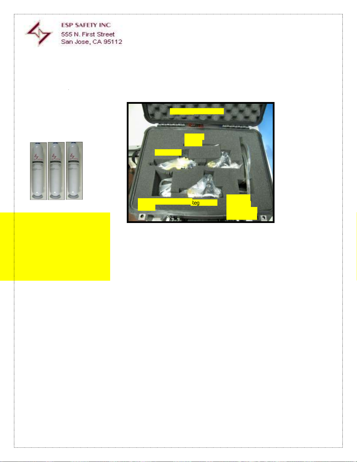
ESP Safety Inc. SSS-903 Calibration Kit for Methane Gas (Part Number 24011-xxx)
Power supply: output voltage 0-30VDC with adjustable current limit (no less than .05mA)
Digital Multimeter (Optional)
Plastic or vinyl tube – 3 pieces of 59.06 inches (1.5M) in lenPGUh
Four control lamps (24VDC) for relay operation verification (Optional)
PC With Windows operating System
Convertor RS232/485 (Or USB to RS-485 Adapter Cable)
ESP Safety Inc. “ESP Commander Program”
ITEM
PART NUMBER
DESCRIPTION
QTY 1 50016-xxx
ZERO GAS CALIBRATION CYLINDER
1 2 50021-xxx
MID-SPAN CALIBRATION GAS CYLINDER (50% LEL)
1 3 50022-xxx
SPAN GAS CALIBRATION CYLINDER (50% LEL)
1
4
40072-xxx
REGULATOR, SINGLE STAGE, FIXED ORIFICE, 500 SCCM
3
5
40074-xxx
CUP, CALIBRATION, SSS-903
1 6 40076-xxx
CASE, TRAVEL, CALIBRATION KIT
1
Crescent
Wrench
Regulator 1
Regulator 3
TG Sensor
Calibration
Cup with ¼”
Tygon tubing
Extra Fittings for Teflon
gaskets
Hard Shell Travel Case
Calibration Gas Cylinders
Zero Gas (0% LEL)
Mid Span Gas (typically 50%LEL)
Span Gas (typically 90% LEL)
Cylinders are supplied with 1 cubic liter of
gas at 1600-1800 PSIG. Replace cylinders
when the internal pressure is lower than
200PSIG
Note: User supplied tanks and
regulators may be employed.
Flow rates must be limited to
10 LPM as measured on a
rotameter.
The following equipment is required for ESP Commander calibration of the SSS-903:
Figure 39- ESP
Safety Inc.
calibration Kit
Methane Gas
Calibration Kit Components
Page 45

Part
Number:
10060-001
Rev:
03
Description:
SSS-903 TG-E
Install Guide
Date:
08/15/2017
Page: 45 of 53
Figure 40 - Wiring Diagram for Bench Calibration
Page 46

Part
Number:
10060-001
Rev:
03
Description:
SSS-903 TG-E
Install Guide
Date:
08/15/2017
Page: 46 of 53
Figure 41 -Launch ESP Commander
Software Program on the user supplied PC
interfaced to the user supplied RS-485 to
USB converter.
Select The COM port for the link between
the PC and converter
ESP Commander will scan for all devices
connected (via MODBUS communication
protocol)
Select the device to be calibrated by “double
clicking”
Page 47

Part
Number:
10060-001
Rev:
03
Description:
SSS-903 TG-E
Install Guide
Date:
08/15/2017
Page: 47 of 53
Device Model
Device relay state
Device Address
Version
Serial Number
Device Address Assignment
Detection Gas
Calibration Values
Alarm Values
Graph of Alarm events
Recording of Real Time Data
Polling Interval
After connecting the SSS gas analyzer to the
PC, ensure that the digital interface is
functional by comparing the SSS-903
settings with those display by ESP
Commander.
REAL TIME ALARM STAUS & DATA FROM SSS-903
ENTER & SET NEW THRESHOLD VALUES
ALARM THRESHOLDS AT SSS-903
Figure 42 -ESP Commander Operating Screen Display and Function:
Page 48

Part
Number:
10060-001
Rev:
03
Description:
SSS-903 TG-E
Install Guide
Date:
08/15/2017
Page: 48 of 53
Figure 43 –Cal Gas Selection
Use the pull down to select the gas to match
the labeling on the sensor.
The gas pull down is pre-programmed with
the required LEL/ppm for the selected gas.
Connect tubing between the gas cylinder
and PGU sensor inlet nipple.
Using the Zero Gas Cylinder, purge the the
cup and PGU sensor by inserting the tubing
from the Zero Gas Cylinder and passing
approximatly one Liter of Gas into the
sensor.
Figure 44- Zero Cal Purge
using ESP Commander
Page 49

Part
Number:
10060-001
Rev:
03
Description:
SSS-903 TG-E
Install Guide
Date:
08/15/2017
Page: 49 of 53
Figure 45- Zero Cal
When measured gas level has stopped
changing, Zero or close to it, Click on Zero.
Current loop out put will equal 4.0mA
The SSS-903-903 will show Zero
Attached the Span Gas Cylinder with the
mixture value as required.
Start a flow into the Calibration cup. After
about 60 seconds, the count will top out. Set
this as Span or the user selected Max % of
the LEL.
Current loop output will equal 20ma.
Hydrogen Sulfide is measured as ppm the
setting for 100%LEL is equal to the screen
value.
Figure 46 -Span Cal with ESP Commander
A second gas with a mixture equal to 50%
LEL may be used for calibration of span or
mid span.
Figure 47 – 50% Span
Level 1,2,3 Alarm levels can now be entered
to the SSS-903 by entering the value and
clicking set.
Stop the flow and remove the Span gas hose
and Cal Cup at this point.
The SSS-903 can now be reassembled and
returned to service.
Note that in the SSS-903 Screen (left) the
Alarm 1, Alarm 2, are RED and the Tri Color
LED Alarm Status is YELLOW.
When the Span gas is removed, the ppm
value will drop to zero and alarms will turn
off when thresholds are crossed.
Figure 48- Setting Alarm Thresholds
Page 50

Part
Number:
10060-001
Rev:
03
Description:
SSS-903 TG-E
Install Guide
Date:
08/15/2017
Page: 50 of 53
Field Repair
The SSS-903 detector has no user serviceable parts. If a problem
should develop, refer to the Troubleshooting information. If it is
determined that the problem is caused by a manufacturing defect,
please return the device to the factory for repair or replacement.
Return
Material
Authorization
(RMA)
Contact ESP Safety Inc at 408-886-9746 to obtain a Return Material Authorization
(RMA) number. In the call, provide the following information:
- Company Name
- Serial Number
- Date of Commissioning
- A brief explanation of malfunction
Pack the unit properly to ensure that no shipping damage occurs and ship prepaid
to:
ESP Safety Inc
555 North First Street
San Jose, CA 95112
Write the RMA number on the front of the shipping carton.
The contents should be carefully removed and verified against the packing list. If any damage has occurred or there is any
discrepancy in the order, please notify ESP Safety Inc. customer service department as soon as possible at (408) 886-9746
or via Email mailto:info@espsafetyinc.com
Warranty
: ESP Safety Inc, 555 North First Street San Jose, CA 95112 USA, guarantees the SSS-903 will be free of manufacturing
defects
for 5 years after date of commissioning, provided the customer follows all guidelines pertaining to installation, operation, and
maintenance detailed in this Operating Manual.During this warranty period, the manufacturer will correct any failures detected
in the SSS-903 or replace any damaged unit
free of charge.
The technical maintenance for the SSS-903 systems consists of periodical external examination and zero setup. The inspection
interval is set by the based upon their operating procedures. Physical inspections of the detector installation should be
performed at regular intervals as determined by customer procedure.Detectors used in corrosive environments should be
replaced at regular intervals. Contact ESP Safety to order replacement
PGU Sensors.
Malfunction / Problem
Possible Cause
Troubleshooting Method
Unit does not perform self test on
power up
Low Power supplied.
Check input voltage to be 18 to 36
VDC range
Following power-up of and self testing
mode completion some functions fail
Microprocessor error
Return to ESP Safety for repair
Unpack A New SSS-903
Maintenance
Troubleshooting
Page 51

Part
Number:
10060-001
Rev:
03
Description:
SSS-903 TG-E
Install Guide
Date:
08/15/2017
Page: 51 of 53
Appendix I: Explosion Proof Design
Page 52

Part
Number:
10060-001
Rev:
03
Description:
SSS-903 TG-E
Install Guide
Date:
08/15/2017
Page: 52 of 53
Appendix II: Warranty & Return Policy
ESP Safety, Inc. (“ESP”) warrants the
under normal use and service for a period of five (5) years, beginning on the date of shipment to the buyer. This
warranty extends only to the sale of new and unused products to the original buyer. ESP’s warranty obligation is
limited, at ESP’s option, to refund of the purchase price, repair, or replacement of a defective product or a component
thereof, to the extent that the product is properly returned to ESP within the warranty period.
This warranty does not include:
a) fuses, disposable batteries or the routine replacement of parts due to the normal wear and tear of the
product arising from use;
b) any product or component which in ESP’s opinion, has been misused, altered, abused, tampered with,
improperly maintained or used, neglected or otherwise damaged by accident or abnormal conditions of
operation, handling or use, or to have deteriorated due to aging of any component made of rubber or any
other elastomer; or
c) any damage or defects attributable to repair of the product by any person other than an authorized dealer,
or the installation of unapproved parts on the product.
The obligations set forth in this warranty are conditional on:
a) proper storage, installation, calibration, use, maintenance and compliance with the product manual
instructions and any other applicable recommendations of ESP;
b) the buyer promptly notifying ESP of any defect and, if required, promptly making the product available for
correction. No goods shall be returned to ESP until receipt by buyer of shipping instructions from ESP. A
return authorization number must be obtained from ESP prior to shipment; and
c) all warranty returns to be shipped pre-paid by buyer.
d) the right of ESP to require that the buyer provide proof of purchase such as the original invoice, bill of sale
or packing slip to establish that the product is within the warranty period.
THE BUYER AGREES THAT THIS WARRANTY IS THE BUYER’S SOLE AND EXCLUSIVE REMEDY AND IS IN LIEU OF ALL
OTHER WARRANTIES, EXPRESS OR IMPLIED, INCLUDING BUT NOT LIMITED TO ANY IMPLIED WARRANTY OF
MERCHANTABILITY OR FITNESS FOR A PARTICULAR PURPOSE. ESP SHALL NOT BE LIABLE FOR ANY SPECIAL,
INDIRECT, INCIDENTAL OR CONSEQUENTIAL DAMAGES OR LOSSES. ESP WILL NOT BE LIABLE FOR LOSS OR
DAMAGE OF ANY KIND CONNECTED TO THE USE OF ITS PRODUCTS OR FAILURE OF ITS PRODUCTS TO FUNCTION
OR OPERATE PROPERLY. IN NO EVENT SHALL ESP’S LIABILITY HEREUNDER EXCEED THE PURCHASE PRICE
ACTUALLY PAID BY THE BUYER FOR THE PRODUCT.
To the extent any provision of this warranty is held invalid or unenforceable by a court of competent jurisdiction, such
holding will not affect the validity or enforceability of any other provision.
Field Repair
The SSS-903 Gas Detector is not intended to be repaired in the field. If a pro b l e m should develop, refer to the
troubleshooting section of this manual. If it is determined that the problem falls within this warranty, please
return the product to ESP as instructed hereunder.
SSS-903 Gas Detector
to be free from defects in material and workmanship
Page 53

Part
Number:
10060-001
Rev:
03
Description:
SSS-903 TG-E
Install Guide
Date:
08/15/2017
Page: 53 of 53
Return Material Authorization (RMA) Number
Contact ESP Safety Inc. at +1-408-886-9746 to obtain a Return Material Authorization (RMA) n umber. Please
provide the following information during your call:
-Company Name
-Product Type
-Serial Number
-Date of Shipment
-Brief explanation of malfunction
Pack the unit properly to ensure that no shipping damage occurs and ship pre-paid to:
ESP Safety Inc.
555 North First Street
San Jose, CA 95112 USA
Write the RMA number on the front of the shipping carton.
 Loading...