

Page 1
MAGPRO-DBS
Intelligent analogue addressable
fire alarm base with built-in sounder
MAGPRO-DBS
Distributor: Elite Security Products Ltd,
Unit 7 Target Park, Shawbank Road
Lakeside, Redditch B98 8YN, UK
http://www.espuk.com
Manufacturer: Teletek Electronics JSC
Address: 14A Srebarna Str, 1407 Sofia,
Bulgaria
Http://www.teletek-electronics.com
1293-CPR-0387
EN54-3, Sounder Type A
2013
Installation Instruction
MAGPRO-DBS is аn addressable Fire Base with built-in Sounder in its body. The fire base is designed for installing in
addressable fire alarm systems which support operation via MAGPRO communication protocol. The device is powered on from
the panel and can be controlled via the communication protocol.
The addressable MAGPRO-DBS fire base supports 32 different tone types at two sound levels. The tone type and sound level are
programmed from the control panel.
The MAGPRO-DBS is compatible for operation with MAGPRO addressable detectors series: HD1, SD1 and HSD1. The device is
designed for easy installation and consists from two parts: mounting plane basis and sounder is a body with factory mounted fire base.
Installation Instructions
Attention: Power off the loop circuit before installing the MAGPRO-DBS addressable fire base!
1. Choose the proper place for installation of the device.
2. Set the device address using MAGPRO-PROG or directly from addressable fire panel. The address must be in the range from 1 to
250.
3. Fix the mounting plane basis on the ceiling of the protected premises using fixings according the mounting surface.
4. Run the loop wires and fix the sounder body to the mounting basis using the supplied screws in the spare parts kit.
5. Connect the fire base to the fire panel using the wiring diagram.
6. Insert a detector - MAGPRO HD1/ SD1/ HSD1 - into the fire base and rotate clockwise until it drops into place - the short mark on
the base fits with that on the sounder body. Continue to rotate the detector until its mark coincides with the long mark on the base - a
click is heard.
Note: The mounted detector on the MAGPRO-DBS base is assigned at different address to the control panel!
7. Program the sounder parameters. Refer to the Programming manual of the control panels MAGPRO16 and MAGPRO96 for
more details.
8. Test the sounder for proper operation.
IP21C
-10°C ÷ +60°C
Installation
~127g
Indoor use
Outdoor use
!
Operating Voltage Range . . . . . . . . . . . . . . . . . . . . . . . . . . . . . 15 - 32VDC
Maximal consumption at communication . . . . . . . . . . . . . . . . . 470 μА @ 27VDC
Maximal consumption:
- main tone type 27, low volume level . . . . . . . . . . . . . . . . . 2,8 mА @ 27VDC
- main tone type 27, high volume level. . . . . . . . . . . . . . . . . 9,8 mА @ 27VDC
Power volume (main tone type 27):
- low volume (up to 100 pcs MAGPRO DBS to the loop) . . . ~ 92dB (A) ± 3dB @ 1m
- high volume (up to 30 pcs MAGPRO DBS to the loop) . . . ~ 99dB (A) ± 4dB @ 1m
Power volume (other tone types): . . . . . . . . . . . . . . . . . . . . . . .
- low volume (up to 100 pcs MAGPRO DBS to the loop) . . . 82-92dB ± 3dB @ 1m
- high volume (up to 30 pcs MAGPRO DBS to the loop) . . . 90-100dB ± 3dB @ 1m
Number of tone types . . . . . . . . . . . . . . . . . . . . . . . . . . . . . . . . 32
Supported communication protocol. . . . . . . . . . . . . . . . . . . . . . MAGPRO
2
Wire Gauge for terminals . . . . . . . . . . . . . . . . . . . . . . . . . . . . . 0,4 - 2.0mm
Relative humidity resistance . . . . . . . . . . . . . . . . . . . . . . . . . . . (93 ± 3)% @ +40°C
Color . . . . . . . . . . . . . . . . . . . . . . . . . . . . . . . . . . . . . . . . . . . . . White
Material . . . . . . . . . . . . . . . . . . . . . . . . . . . . . . . . . . . . . . . . . . . ABS
Dimensions with mounted detector MAGPRO HD1/ SD1 . . . . . 102 x 63mm
Dimensions with mounted detector MAGPRO HSD1 . . . . . . . . 102 x 70mm
TECHNICAL SPECIFICATIONS
18020177; RevB; 04/2015
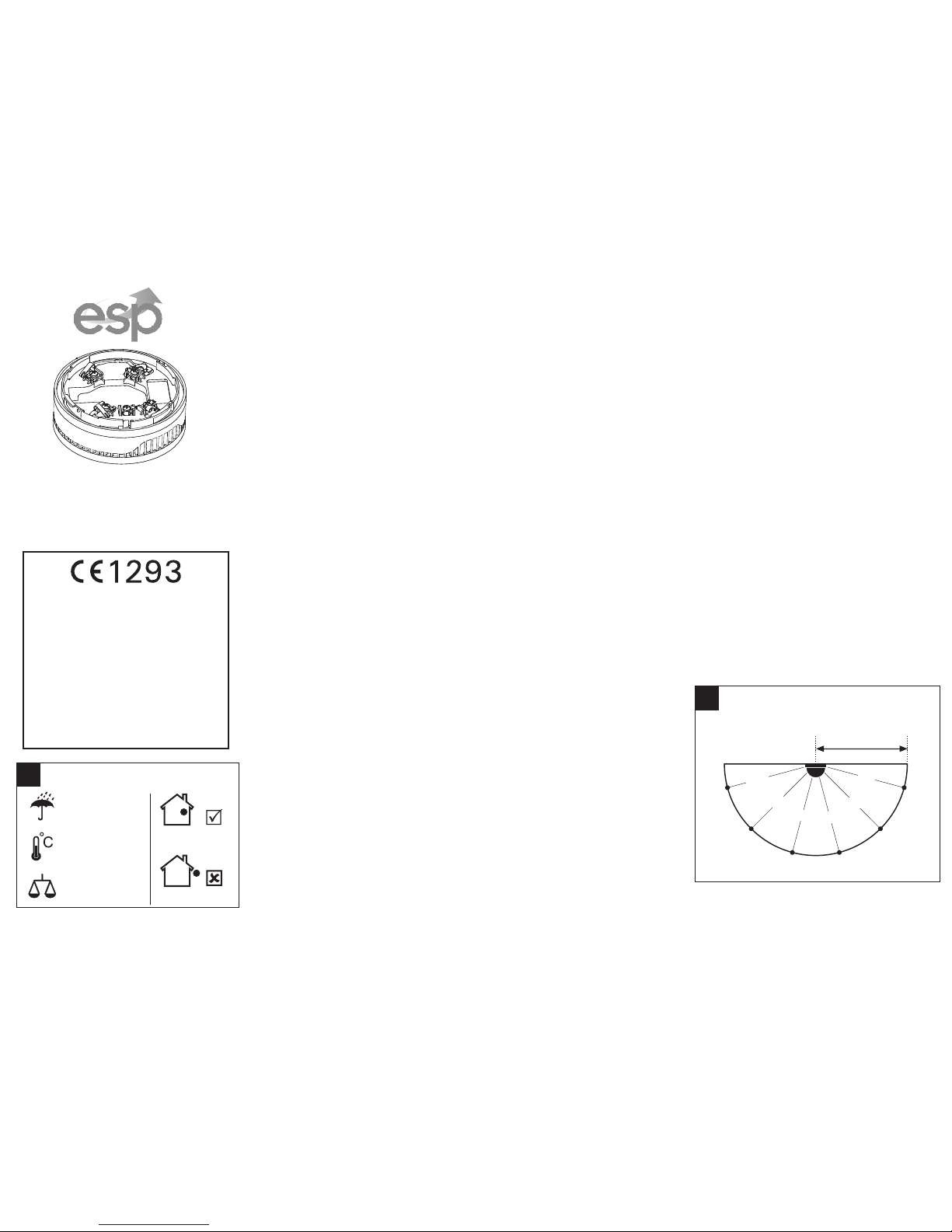
!
A-weighted sound
level diagram
96dB
102dB
103dB
95dB
98dB
1m
97dB
15°
45°
75°
105°
135°
165°
ATTENTION: Read carefully this installation
Instructions before installing the device!
This manual is subject to change without notice!
Page 2
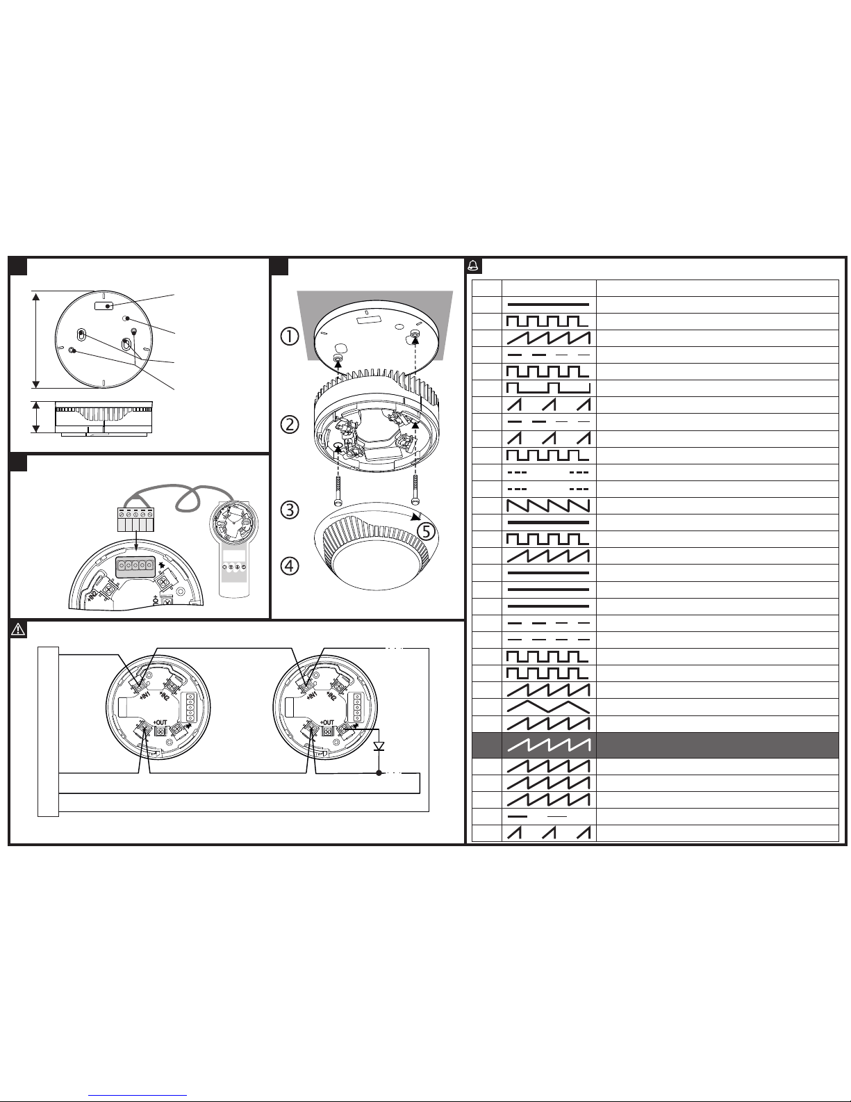
Tone types and description
1
Tone Tone Type Tone Description
2
3
4
5
6
7
8
9
10
11
12
13
14
15
16
17
18
19
20
21
22
23
24
25
26
27
28
29
30
31
32
970Hz
800Hz/970Hz @ 2Hz
800Hz - 970Hz @ 1Hz
970Hz 1s OFF/1s ON
970Hz, 0.5s/ 630Hz, 0.5s
554Hz, 0.1s/ 440Hz, 0.4s (AFNOR NF S 32 001)
500 - 1200Hz, 3.5s/ 0.5s OFF (NEN 2575:2000)
420Hz 0.625s ON/0.625s OFF (Australia AS1670 Alert tone)
500-1200Hz, 0.5s/0.5s OFF x 3/1.5s OFF (AS1670 Evacuation)
550Hz/440Hz @ 0.5Hz
970Hz, 0.5s ON/0.5s OFF x 3/ 1.5s OFF (ISO 8201)
2850Hz, 0.5s ON/0.5s OFF x 3/1.5s OFF (ISO 8201)
1200Hz - 500Hz @ 1Hz (DIN 33 404)
400Hz
550Hz, 0.7s/1000Hz, 0.33s
1500Hz - 2700Hz @ 3Hz
750Hz
2400Hz
660Hz
660Hz 1.8s ON/1.8s OFF
660Hz 0.15s ON/0.15s OFF
510Hz, 0.25s/ 610Hz, 0.25s
800/1000Hz 0.5s each (1Hz)
250Hz - 1200Hz @ 12Hz
500Hz - 1200Hz @ 0.33Hz
2400Hz - 2900Hz @ 9Hz
2400Hz - 2900Hz @ 3Hz
2500Hz (main sound frequency)
800Hz - 970Hz @ 100Hz
800Hz - 970Hz @ 9Hz
800Hz - 970Hz @ 3Hz
800Hz, 0.25s ON/1s OFF
500Hz - 1200Hz, 3.75s/0.25s OFF (AS2220)
Fire Panel
RI
+Loop
-Loop
-Loop
+Loop
DBS DBS
Wiring Diagrams
RI - Remote Indicator; +Loop - Positive loop wire; - Negative
Loop - loop wire
3
Installation
1
Dimentions and Mounting
102 mm33 mm
Mounting holes
Opening for fixing
to the conduit box
Holes for fixing the
common body
Opening for
running cables
2
Address programming
Note: You may also
program the
address directly
from the
fire panel.
Down
Right
Up
Modify
Esc
Enter
MAGPRO-
PROG
- Use the cable with
5-pin terminal.
 Loading...