

Page 1
MAGPRO-2i2O
EN54-18
!
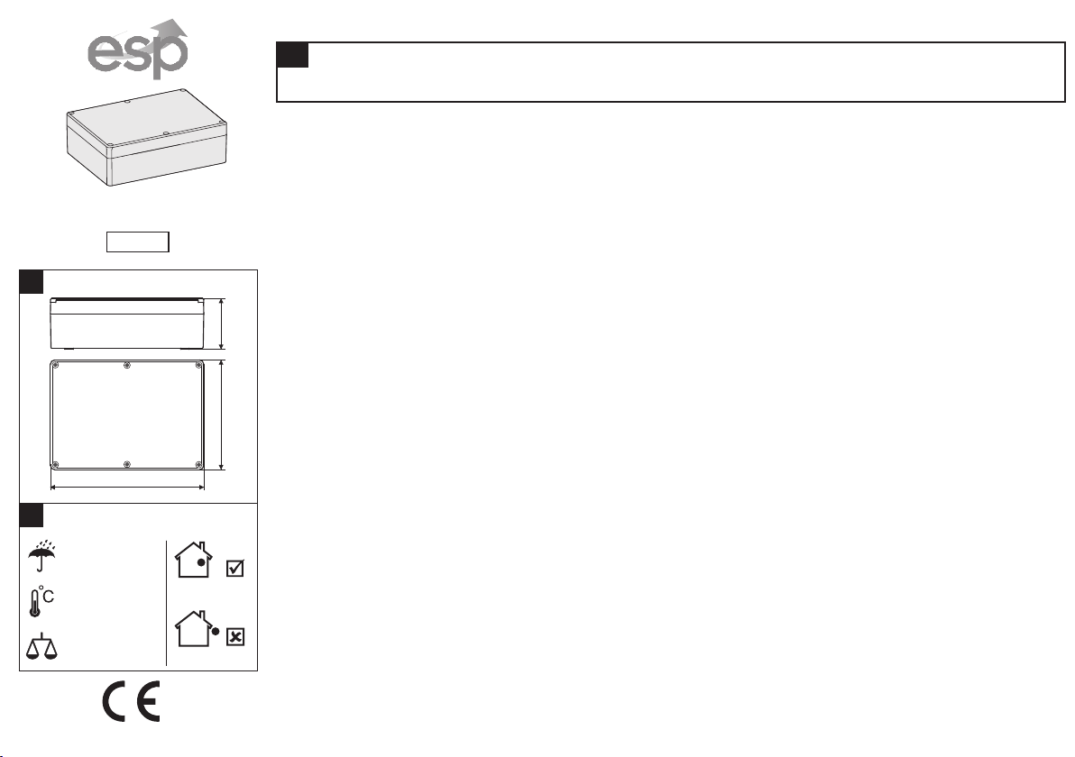
Dimensions
126mm 57mm
Installation Instructions
!
ATTENTION
The MAGPRO-2i2O addressable module must be connected only to fire panels from MAGPRO Series!
General Description
MAGPRO-2i2O is an addressable input-output module. The module monitors 2 analogue input signals and
controls 2 relay outputs.
MAGPRO-2i2O is powered on from the fire panel and can be controlled via the communication protocol.
The module is mounted is a separate small plastic box suitable for wall mounting.
Installation
Attention: Power off the loop circuit before installing the MAGPRO-2i2O addressable module!
1.Choose the proper place for installation of the module. Undo the screws of the cover and open the box.
2. Set the module address using MAGPRO-PROG programming tool. The address must be in the range from
1 to 250. The set address is one for the entire module.
3. Dismount the module’s PCB from the box bottom. Mark the mounting holes on the installation surface. Drill
holes at the appropriate box side and run the cables to the module’s loop and input-output terminals.
4. Mount the box bottom at the place of installation. Mount the PCB back on place.
5. Connect the cables to the loop and input-output terminals of the module according the shown Connection
diagrams.
6. Close the cover of the plastic box and fix it to the bottom with the supplied screws.
7. Test the module for proper operation and LED indication.
!
Installation
IP40
-10°C ÷ +60°C
~320g
1293-CPD-0258
176mm
Indoor use
Outdoor use
TECHNICAL SPECIFICATIONS
Operating voltage . . . . . . . . . . . . . . . . . . . . . 15÷32 VDC
Consumption stand-by mode . . . . . . . . . . . . 235µА@27VDC
Nom. current consumption . . . . . . . . . . . . . . 260µА@27VDC
Outputs, electrical characteristics (max.) . . . DC 30V/1A; AC 125V/0.5A
Current consumption with 1 LED on . . . . . . . 3.5mA
Current consumption with 2 LEDs on . . . . . . 7mA
Installation wires . . . . . . . . . . . . . . . . . . . . . . 0.4mm ÷ 2.0mm
2 2
Relative humidity . . . . . . . . . . . . . . . . . . . . . . ≤93% @ +40°C
Material (plastic) . . . . . . . . . . . . . . . . . . . . . . PS
Color . . . . . . . . . . . . . . . . . . . . . . . . . . . . . . . Gray
Standard . . . . . . . . . . . . . . . . . . . . . . . . . . . . EN54-18
Distributor: Elite Security Products Ltd, Unit 7 Target Park, Shawbank Road Lakeside, Redditch B98 8YN, UK http://www.espuk.com
Manufacturer: Teletek Electronics JSC, 14 Srebarna Str., 1407 Sofia, Bulgaria, http://www.teletek-electronics.com
18020170; RevD; 03/2017
Page 2
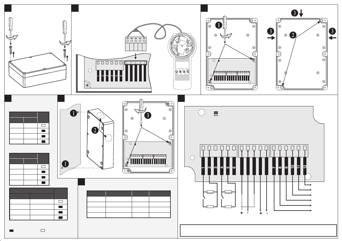
1 2
Open the box
Address programming
- Use the cable with
5-pin terminal.
Line + >
Line - >
Izolator >
Line + >
Line - >
Up
Esc
Right
Modify
MAGPRO-
PROG
3
Mounting and Cable holes
Down
Enter
Possible places for
drilling of cable holes
Mounting
holes
!
LED Indication
1. OUTPUTS
Status
OUT 1
OFF
OFF
ON
ON
OUT 2
OFF
ON
OFF
ON
Red
LED
2. INPUTS
Status
IN 1
Normal
Normal
ON
ON
IN 1
Normal/ON
Short/Open
Normal/ON
Short/Open
IN 2
Normal
ON
Normal
ON
Status
Red
LED
IN 2
Normal/ON
Normal/ON
Short/Open
Short/Open
Legend:
- LED Lights on; - LED Lights off
4
Yellow
LED
Fix the
box on the
installation
surface
Installation
Run the
cables
!
INPUTS Status
Status Description
SHORT
NORMAL
* R - resistance between the input and GND
** I - current at the input
ON
OPEN
Short circuit
Activation
Stand-by mode
Open circuit
R* I**
<13k
13k - 36k
36k - 90k
>90k
>54µA
38µA - 54µA
23µA - 38µA
<23µA
5
Connection diagrams
LED
(red-yellow)
Input 1
56k
Input 2
56k
Loop IN
Line +
Line -
Isolator
Line +
Isolator
Loop OUT
Line -
Output 1
Output 2
NO
Common
NC
56k
56k
NO
Common
NC
Loop
ATTENTION: When you use the integrated short circuit isolation module connect one
of the “+Loop” loop lead to the “Isolator” terminal of the module.
Loop
 Loading...