

Page 1

INSTALLATION
AND PROGRAMMING
MANUAL
Intelligent Interactive Analogue Addressable
Fire Alarm Control Panel
MAGPRO16
Attention:
This manual contains information on limitations regarding product use and
function and information on the limitations as to liability of the manufacturer.
The entire manual should be carefully read.
The information in this manual is a subject to change without notice!
Page 2

MAGPRO16 Addressable Fire Alarm Panel – Installation and Programming Manual
Table of Contents
1. INTRODUCTION ........................................................................................................................................................... 5
1.1. General Description....................................................................................................................................... 5
1.2. General Specifications .................................................................................................................................. 5
1.2.1 General Technical Specifications .................................................................................................... 5
1.2.2 Possible Hardware Configurations .................................................................................................. 6
1.2.3 Environment ..................................................................................................................................... 6
1.2.4 Electrical Characteristics ................................................................................................................. 6
2. INSTALLATION ............................................................................................................................................................. 8
2.1. Wall Mounting ................................................................................................................................................ 8
2.2. System Components ..................................................................................................................................... 9
2.2.1 Front panel ....................................................................................................................................... 9
2.2.2 Configuration of the basic modules ............................................................................................... 11
2.2.3 Description of the main PCB (control panel) ................................................................................. 11
2.3. Connection of Signaling Devices ................................................................................................................ 13
2.3.1 Connecting of Sounders ................................................................................................................ 13
2.3.2 Connecting of Signaling Devices ................................................................................................... 13
2.3.3 Connecting to the Specialized Inputs ............................................................................................ 13
2.3.4 Loop Controller .............................................................................................................................. 14
2.3.5 Maximum Permissible Cable Length ............................................................................................. 15
2.4. Connecting to the Main Power Source........................................................................................................ 16
2.5. Connecting the Accumulator Battery........................................................................................................... 16
2.6. Connecting a Heat Printer ........................................................................................................................... 17
2.7. Connecting a Network Interface Card (MAGPRO-NIC) .............................................................................. 17
2.8. Connecting an AJAX LAN Communication Module .................................................................................... 17
3. PROGRAMMING TYPES ............................................................................................................................................ 18
3.1. Programming via MAGPRO Programming Software .................................................................................. 18
3.2. Programming via Panel’s Keyboard ............................................................................................................ 18
3.3. Firmware Update ......................................................................................................................................... 18
3.3.1 Firmware Update from Computer .................................................................................................. 18
3.3.2 Firmware Update from USB Drive ................................................................................................. 19
3.3.3 Copying Image File from the Panel to USB Drive ......................................................................... 19
4. FULL HARDWARE RESET ......................................................................................................................................... 19
5. PROGRAMMING OF MAGPRO16 FIRE ALARM PANEL ..................................................................................... 20
5.1. General Information for Programming and Operation ................................................................................. 20
5.2. Codes and Access Levels ........................................................................................................................... 20
6. DESCRIPTION OF THE OPERATION MODES ......................................................................................................... 22
6.1. Review of Alarm Events .............................................................................................................................. 22
6.2. Review of Fault Events................................................................................................................................ 22
6.3. Review of Disablements .............................................................................................................................. 23
6.4. Review of Running Tests ............................................................................................................................ 23
6.5. Review of Warning Messages ..................................................................................................................... 24
6.6. Silencing the Internal Buzzer ...................................................................................................................... 25
6.7. Silencing the Sounders ............................................................................................................................... 25
6.8. Activate Evacuation ..................................................................................................................................... 25
6.9. Resetting the Panel ..................................................................................................................................... 25
6.10. Indication Test ........................................................................................................................................... 25
7. DESCRIPTION OF THE PROGRAMMING MENUS ................................................................................................... 26
7.1. View History Log Menu ............................................................................................................................... 26
7.1.1 Review of Full Events List ............................................................................................................. 26
7.1.2 Review of List of Events by Date ................................................................................................... 27
7.1.3 Deleting the Events in the LOG file ............................................................................................... 27
7.1.4 Printing Events ............................................................................................................................... 27
7.1.5 Printer Settings .............................................................................................................................. 27
7.2. Zones Menu ................................................................................................................................................ 28
7.2.1 General Submenus ........................................................................................................................ 28
7.2.2 Zones Testing ................................................................................................................................ 28
7.2.3 Disabling Zones ............................................................................................................................. 29
7.2.4 Programming Zone Parameters .................................................................................................... 29
2
Page 3

MAGPRO16 Addressable Fire Alarm Panel – Installation and Programming Manual
7.2.5 Zone Name .................................................................................................................................... 29
7.2.6 Zone Operation Modes .................................................................................................................. 29
7.2.7 Programming Delays Т2 ................................................................................................................ 30
7.2.8 Arranging Zones in Groups ........................................................................................................... 31
7.3. Devices Setup Menus ................................................................................................................................. 31
7.3.1 Submenus for General Setting ...................................................................................................... 31
7.3.2 Saving the New Found Devices .................................................................................................... 32
7.3.3 Deleting Devices ............................................................................................................................ 32
7.3.4 Disabling Devices .......................................................................................................................... 32
7.3.5 Programming of Device Parameters ............................................................................................. 33
7.4. Addressing Menus ....................................................................................................................................... 39
7.4.1 Set Address ................................................................................................................................... 39
7.4.2 Change Address ............................................................................................................................ 39
7.4.3 Self-Addressing ............................................................................................................................. 40
7.5. Panel Outputs Menus .................................................................................................................................. 41
7.5.1 Sounders Outputs .......................................................................................................................... 41
7.5.2 Extinguishing Output...................................................................................................................... 41
7.5.3 Fire Output ..................................................................................................................................... 42
7.5.4 Fault Output ................................................................................................................................... 42
7.5.5 Relay Outputs ................................................................................................................................ 42
7.6. General Settings Menu ............................................................................................................................... 43
7.6.1 Access Codes ................................................................................................................................ 43
7.6.2 Setting the Date and Time ............................................................................................................. 44
7.6.3 Setting Day/ Night Alarm Modes ................................................................................................... 44
7.6.4 Panel General Settings .................................................................................................................. 45
7.6.5 Delay Т1 ........................................................................................................................................ 45
7.6.6 Sounders Mode ............................................................................................................................. 45
7.7. Save Configuration Menu ............................................................................................................................ 46
7.8. Restore Defaults Menu................................................................................................................................ 46
7.9. Software Revision ....................................................................................................................................... 46
7.10. Network ..................................................................................................................................................... 47
7.10.1 Network Settings .......................................................................................................................... 47
7.10.2 Panels Settings ............................................................................................................................ 47
7.11. Active Isolators Menu ................................................................................................................................ 48
7.12. Access Level 1 .......................................................................................................................................... 48
APPENDIX А ................................................................................................................................................................... 49
APPENDIX B ................................................................................................................................................................... 50
APPENDIX C ................................................................................................................................................................... 51
APPENDIX D ................................................................................................................................................................... 52
APPENDIX E ................................................................................................................................................................... 53
3
Page 4
MAGPRO16 Addressable Fire Alarm Panel – Installation and Programming Manual
STANDARDS AND CONFORMITY
The addressable fire alarm control panel MAGPRO16 is designed and certified according and with conformity to
EN 54 – 2/4 standard. Conforms and approved in accordance with CPR (Construction Products Regulation).
Distributor: Elite Security Products Ltd, Unit 7 Target Park, Shawbank Road Lakeside, Redditch B98 8YN, UK
http://www.espuk.com
Manufacturer: Teletek Electronics JSC, 14 Srebarna Str., 1407 Sofia, Bulgaria
DoP No: 002
EN 54-2:1997/A1:2006/AC:1999; EN 54-4:1997/A2:2006/AC:1999
MAGPRO16
Intended for use in fire detection and fire alarm systems in and around buildings.
Essential Characteristics
Performance
Performance under fire conditions
Pass
Response delay (response time to fire)
Pass
Operational reliability
Pass
Durability of operational reliability and response delay: temperature resistance
Pass
Durability of operational reliability: humidity resistance
Pass
Durability of operational reliability: vibration resistance
Pass
Durability of operational reliability: electrical resistance
Pass
4
Page 5

MAGPRO16 Addressable Fire Alarm Panel – Installation and Programming Manual
1. INTRODUCTION
1.1. General Description
MAGPRO16 is an addressable fire panel with maximum coverage of 16 zones and connecting and up to 2 loops. The
panel supports communication protocol MAGPRO (MAGPRO16-L250 Loop) and operation with MAGPRO
addressable device series.
Every MAGPRO16-L250 Loop provides up to 250 devices (detectors and modules, regardless of the
type).
An arbitrary number of devices can be added to each zone thus ensuring the easy adaptation of the system to any type
of configuration.
To avoid or significantly diminish problems when mounting the system it must be carefully planned prior to installation.
This includes: setting an address for every device and planning a name of maximum 40 digits (including the
spaces) for each address, thereby ensuring easy access to the device.
According to the acting standards for establishing fire systems and the plan of the building, the devices must
be grouped in zones.
1.2. General Specifications
The front panel consists of LCD module (4 rows x 40 symbols), functional buttons and system status LED indication.
Separate access level passwords provide access to the functions of the panel.
The fire alarm panel is designed on module structure as in the metal cabinet there are provided additional places for
mounting of a second loop controller for Loop 2 (Loop 1 is built-in the main PCB), LAN module and redundant network
module.
The panel has a built-in real time clock and calendar, allowing day and night time modes of work.
Switching over between the two modes can be automatic or manual. Events like FIRE, RESET, FAULT, etc., are saved
in the memory, thereby creating an event log-file. It contains the time and date, the address of the device, the name of
the device, the zone number, the name of the zone, etc.
1.2.1 General Technical Specifications
Loops - 1 to 2:
o Loop 1 is built-in in the main board
o Loop 2 – optional, separately mounted to the main control panel
Number of loop devices:
o Up to 250 devices (modules and/ or detectors regardless of the type) for every loop (max. 500 for the
entire system)
16 operation zones
5
Page 6
MAGPRO16 Addressable Fire Alarm Panel – Installation and Programming Manual
16 groups for zones’ organization
5 monitored potential outputs:
o SND1 (Sounder 1)
o SND2 (Sounder 2)
o FIRE
o FAULT (In case of Fault event the output is deactivated.)
o EXT (Extinguishing/ Fire Protection – An output for sending an fire alarm signal to automatic fire
extinguishing system)
3 specialized inputs:
o In AmC* (Input Alarm Confirmation)
o In PC* (Input Protection Alarm Confirmation)
o In FP* (Input Fault Protection Panel)
* Covers the requirements on standard VdS 2540
4 non-monitored, programmable relay outputs with parameters: 15A@24VDC
Display – letter and digits LCD module (4 rows х 40 symbols)
Built-in real time clock, supported from integrated lithium battery - 3V, CR3032 type
Memory log file for up to 10240 system events
Comprehensive day/night mode facility
2 Steps of alarm levels (T1 and T2)
Supports external thermo printer
Multilanguage support for operation menus
Easy software update via computer or USB drive
Designed according the requirements of EN54-2/4
Metal box cabinet for wall mounting: bottom (306х412х81mm) and cover (310х416mm)
1.2.2 Possible Hardware Configurations
Minimal Configuration
o Control panel (main PCB with one built-in loop controller)
o Indication (indication PCB with mounted LCD module)
o Power supply source
Maximal Configuration
o Control panel (main PCB with one built-in loop controller)
o Indication (indicator PCB with mounted LCD module)
o Power supply source
o MAGPRO16-L250 Loop controller (for the second loop)
o LAN Communication module
o RS485 Redundant Network controller
1.2.3 Environment
Degree of protection: IP30
Operation temperature: -5ºС up to +40ºC
Relative humidity: up 95% (without condense)
Storage temperature: -10ºС up to +60ºC
Weight (without the battery): ~ 4.2 kg.
1.2.4 Electrical Characteristics
Earth Connection
The earth connection has to be realized in accordance with the rules for the electrical safety with the total resistance in
the circuit lower than 10Ω. It is mandatory to connect the main power supply cable to the middle input of the fire panel
terminal – see also item 2.4 Main power connection.
ATTENTION: Do not instal the fire panel near power electromagnetic fields (radio equipment,
electric motors, etc.)!
6
Page 7
MAGPRO16 Addressable Fire Alarm Panel – Installation and Programming Manual
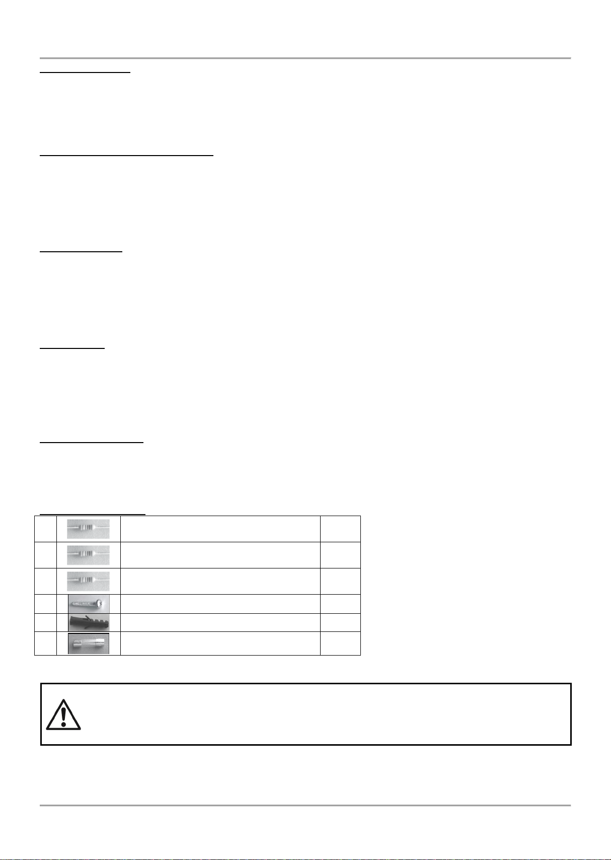
1 Resistor 10k ± 5%, 0.25W
6 pcs
2
Resistor 47k ± 5%, 0.25W
4 pcs
3
Resistor 20k ± 5%, 0.25W
3 pcs
4
Screw 4.2х38, cross slot DIN7981
4 pcs
5
Anchor 6х30mm
4 pcs
6
Fuse 4А, glass time-delay type 5x20mm
(for the power supply)
4 pcs
Main power supply
In normal operating conditions, the fire panel is powered from the mains voltage line. In case of mains voltage line loss
the fire panel is equipped with one rechargeable battery. The characteristics of the main power supply are as follows:
Main power supply: 90 264 VAC
Frequency: 47 440 Hz
Electrical output: 4.2 А
Backup (accumulator) power supply
Voltage output (U): 13,65V
Accumulator battery: 1 x 12V / 18Ah, sealed lead-acid type rechargeable battery
Internal resistance of the accumulator battery Ri: < 0.3Ω
Max. dimensions of the accumulator battery: 167х181х76mm
Type of the battery connection: with a cable lug, Ø5mm (M5) or cable shoe (according the type of the battery
terminals)
Loading capacity
Max. loading capacity of one loop: 500 mA DC
Max. loading capacity of AUX output: 500 mA DC
Max. loading capacity of outputs SND1 and SND2: 500 mA DC
Max. loading capacity of outputs FIRE, FAULT and EXT: 300 mA DC
Max. total loading capacity (sum of the four mentioned above): 2.0 A DC
Programmable relay outputs: 15A@24VDC
Consumption
From the main power supply in standby mode:
o For a minimum configuration: 60 mA AC
o With mounted second loop controller: 65 mA AC
From the backup power supply in FAULT mode and generated message ‘AC loss’:
o For a minimum configuration: 125 mA DC
o With mounted second loop controller: 213 mA DC
List of the used fuses
Main power supply: 4А, Т type, glass time-delay fuse, size 5х20mm
AUX output: 0,5А, PTC type, resettable fuse
Outputs: 0.3А, PTC type, resettable fuse
Accumulator: 7.0А, PTC type, resettable fuse
List of spare parts kit:
ATTENTION!
Qualified specialists only should install the panel.
The electronic components of the panel are vulnerable to electrostatic discharge.
Never add or turn off components which are being power supplied!
7
Page 8
MAGPRO16 Addressable Fire Alarm Panel – Installation and Programming Manual
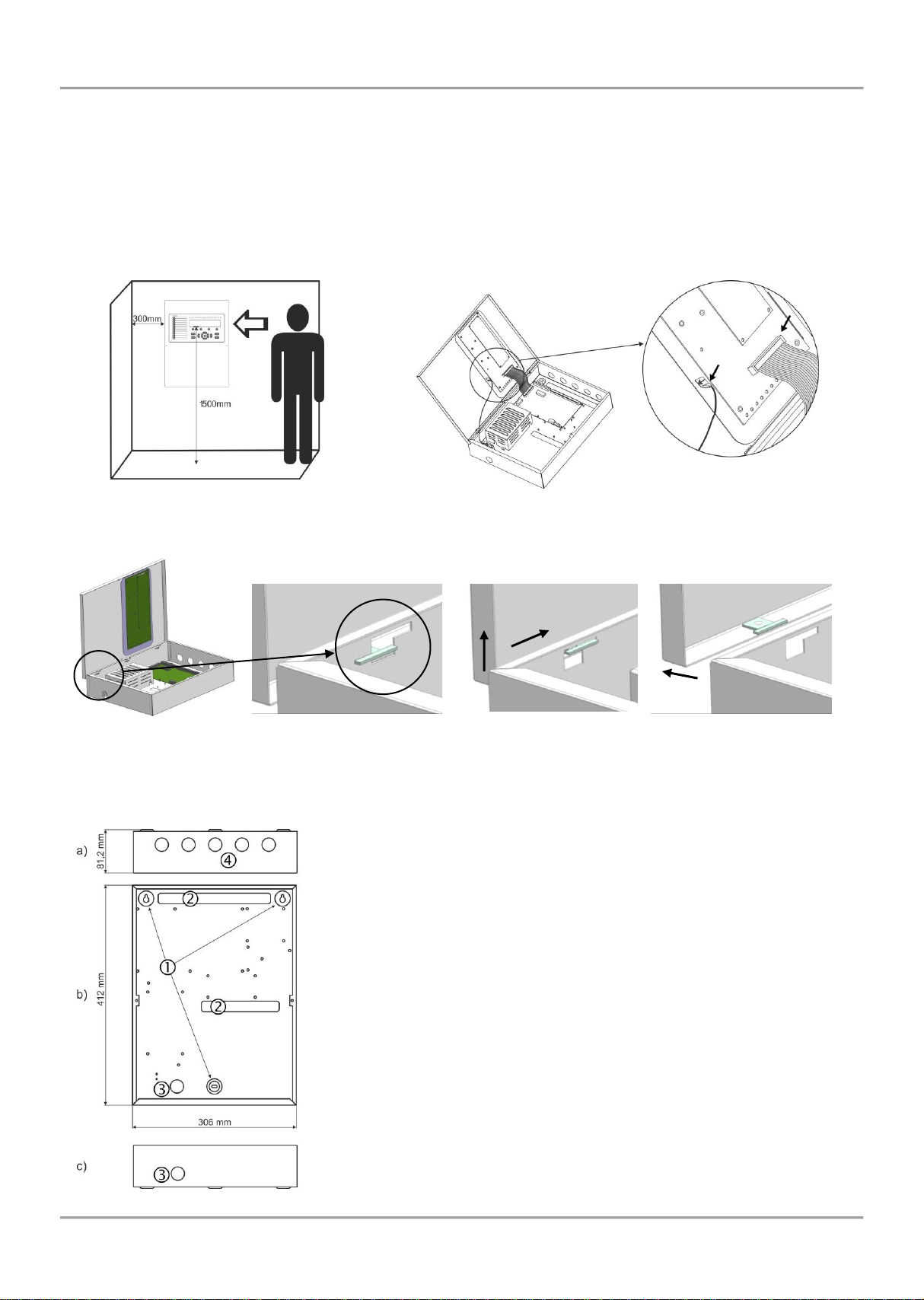
2. INSTALLATION
2.1. Wall Mounting
• The panel must be installed in a clean dry place and must not be subjected to impact or vibrations (Figure 1). It must
be situated far from heating appliances. The temperature must be within -5ºС and + 50ºC. The fire panel is not
waterproof!
• Unpack the panel and observe for visible damages due to bad transport or incorrect storing.
• Open the front cover and disconnect the flat indication cable and the earthling point (Figure 2).
Figure 1 Figure 2
• Remove the front cover as dismount the side hinges (Figure 3).
Figure 3
• Choose inlets for the main power supply cable, loops, sounders, control devices, etc. Remove the metal cap element
just from those holes for cable running (Figure 4).
Figure 4 – Elements of the metal bottom:
а) View from above;
b) Front view;
c) View from below.
1 – Main mounting holes.
2 – Holes for cable running.
3 – Holes for main power supply cable running, protected with a metal cap
element.
4 – Additional holes for cable running, protected with a metal cap element.
8
Page 9
MAGPRO16 Addressable Fire Alarm Panel – Installation and Programming Manual
LED
Indication/ Description
GENERAL FIRE (red)
Lights on permanently in case of fire alarm event – fire alarm signal from an
automatic or manual call point, or other auxiliary device connected to a panel input.
GENERAL FAULT (yellow)
Lights on permanently in case of fault event in the system.
SYSTEM FAULT (yellow)
CPU FAULT. Lights on permanently in case of main microprocessor fault.
DELAY (yellow)
Lights on permanently in daytime mode and set time delay for one or several
outputs.
DISABLE (yellow)
Light on permanently in active disablement in the system.
TEST (yellow)
Light on permanently in system test mode.
SOUNDERS FAULT/ DISABLED
(yellow)
The LED will be active in case of fault or disablement of the sounders circuits. The
indication is as follows:
- Blinking in case of fault event in the sounder circuits.
- Lighting on when the sounder circuits are disabled.
FIRE CONFIRMED (yellow)
FIRE ALARM CONFIRMATION. Lights on permanently in activation of the
specialized “In AmC” input – see the description on page 12.
FIRE OUTPUT FAULT/ DISABLED
(yellow)
The LED will be active in case of fault or disablement of the FIRE relay output. The
indication is as follows:
- Blinking in case of fault event.
- Lighting on when the output is disabled.
• Use the template in the set to fix the mounting holes of the metal box on the wall.
• Drill holes (suitable for anchors Ø6mm) on the wall and fix the metal box.
• Route the external cables onto the back box, make off connection glands etc., BUT DO NOT make any connections
at this stage. ENTER THE MAINS CABLE THROUGH ITS OWN CABLE ENTRY POINT AND KEEP MAINS WIRING
AWAY FROM SYSTEM AND OTHER LOW VOLTAGE WIRING.
• Connect the mains supply and earth to the power supply terminal (see Figure 16), BUT DO NOT apply the main
electrical supply at this stage.
• Place the battery in an upright position.
• Mount the front cover back to the bottom as mount the hinges in the reverse order of that described on Figure 3.
• Connect back the flat cable for the indication and the earthling point (Figure 2).
• Proceed with initial power up of the system and testing.
• When you finish with power up and testing steps and the panel is normal operation mode you must fix the front cover
to the bottom with the two screws for the spare parts kit.
2.2. System Components
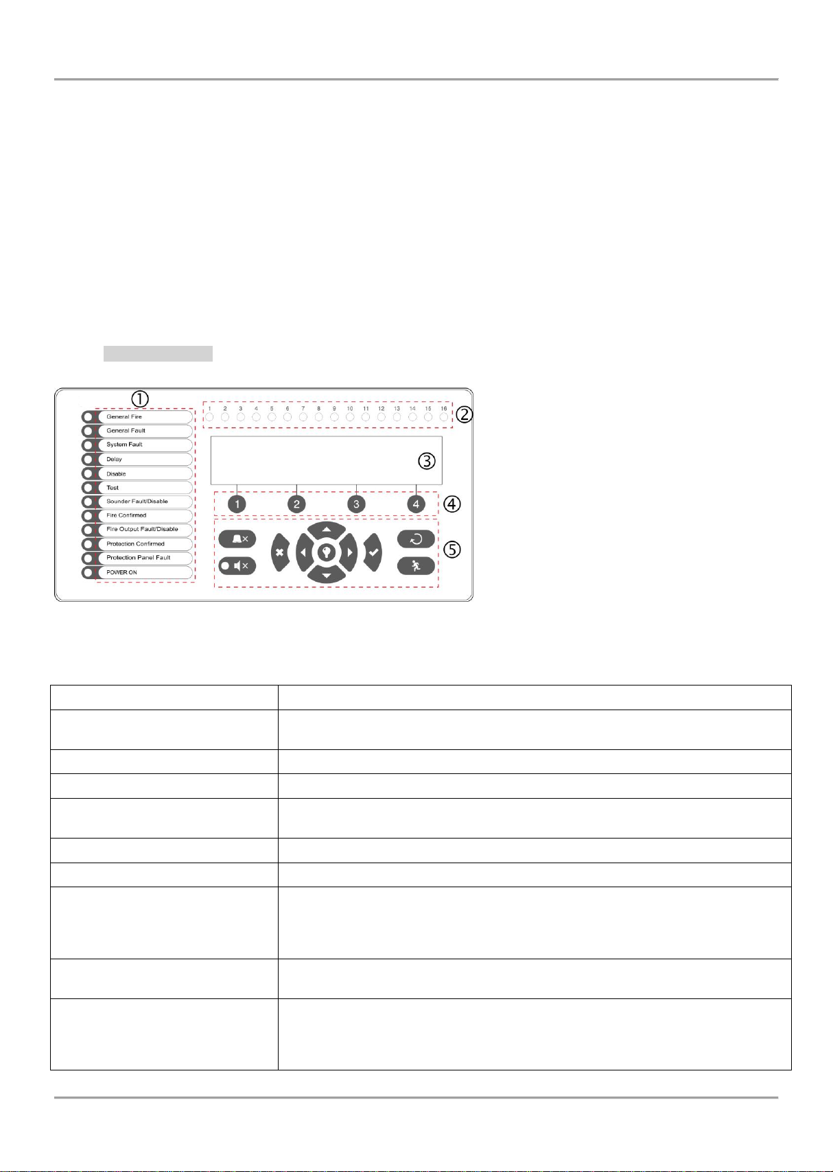
2.2.1 Front panel
Description of the front panel elements:
1 – LED indication for the system status. The
descriptions are printed on the paper label and
can be changed if needed, including for
language change. The paper label is placed in a
special opening on the inner side of the
indicator PCB, over the flat cable for the
indication.
2 – LED indication for the used zones
3 – Letters and digits LCD-module (4х40)
4 – Functional digits buttons
5 – Control and navigation buttons
Figure 5
1 – Description of system status LED indication:
9
Page 10
MAGPRO16 Addressable Fire Alarm Panel – Installation and Programming Manual
PROTECTION CONFIRMED
(yellow)
EXTINGUISHING STARTED CONFIRMATION. Lights on permanently in
activation of the specialized “In PC” input – see the description on page 12.
PROTECTION PANEL FAULT
(yellow)
EXTINGUISHING SYSTEM FAULT. Lights on permanently in activation of the
specialized “In FP” input – see the description on page 12.
POWER ON (green)
MAIN POWER SUPPLY ON. Lights on permanently in presence of 230V main
power supply.
SILENCE ALARM (yellow)
THE SOUNDERS ARE SILENCED. Lights on permanently when the sounders are
silenced (the LED is situated next to the button).
LED
Indication/ Description
Zone indicators (red)
1 - 16
FIRE IN A ZONE. Lights on permanently in case of fire alarm in a zone. Blinking
when the zone is in fire test mode.
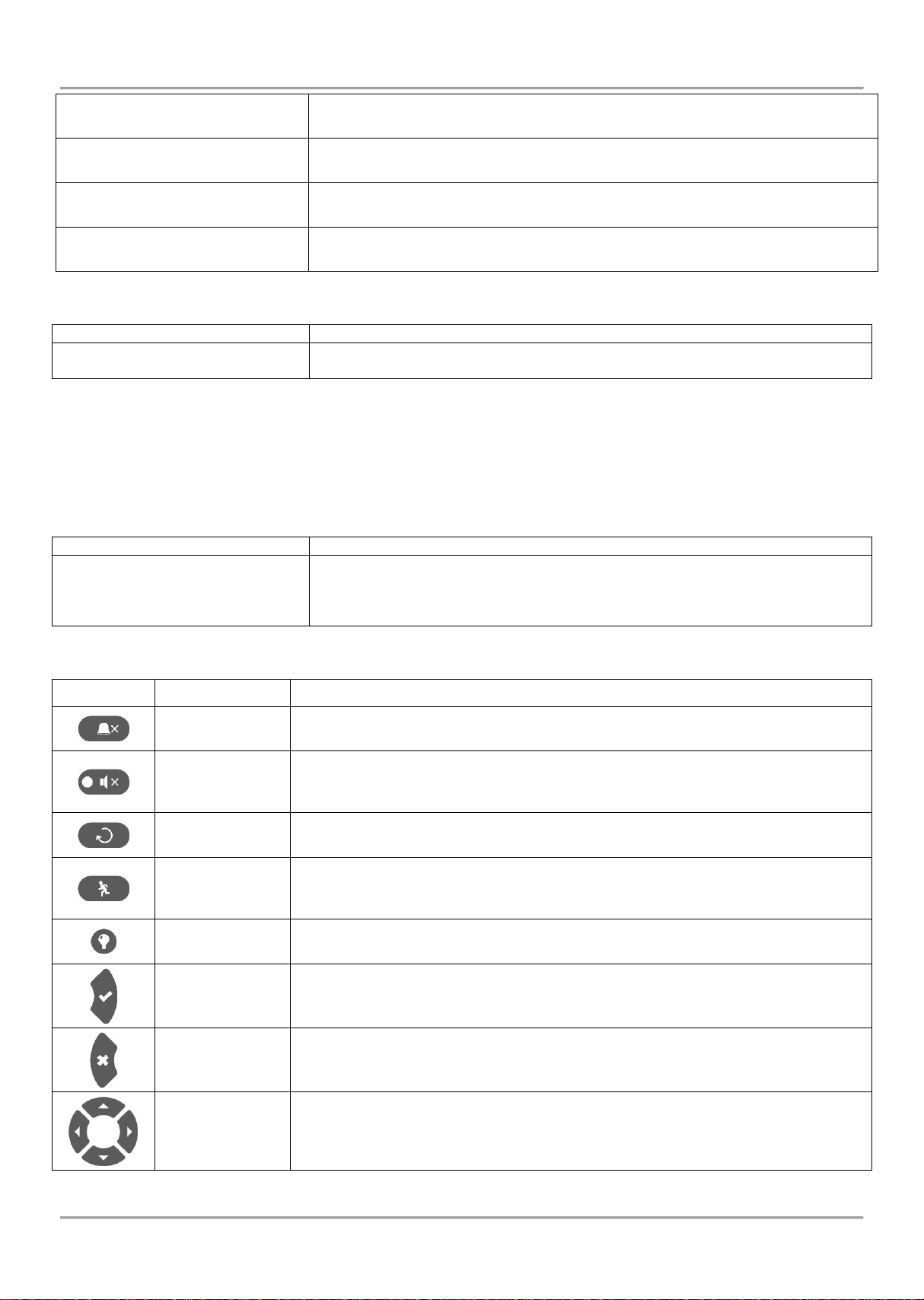
Button
Description
Functional digit buttons
1 - 4
The buttons are active at access levels 2 and 3, and have the following meaning:
- Introducing of access codes.
- Functional submenu entry.
- Changing of value or parameter status.
Button
Action
Description
Silence Buzzer
The button is active at access levels 1, 2 and 3. The button functionality is
deactivation of the internal buzzer (except for the “Protection Panel Fault” event).
Silence
Sounders
The button is active at access levels 2 and 3. The button functionality is
deactivation of the sounders in case of fire alarm event. After pressing the button
the LED next to it is lighting in yellow.
Reset
The button is active at access levels 2 and 3. The button functionality is resetting
the panel without switching off the main power supply.
Evacuation
The button is active at access levels 1*, 2 and 3. The button immediately activates
the sounders – the sounder delay is ignored if present.
* In case of fire alarm event in a zone and set sounder delay.
Buzzer and LED
general test
The button will activate all LEDs on the front panel – for events and zones, as and
the internal buzzer. The next pressing of the button deactivates the test.
ENTER
(Confirmation)
The button is active at access levels 1, 2 and 3. Use the button to confirm the
entered values and parameters; in the devices and zones menus use the button to
enter in a submenu for name and status changing.
CANCEL
(Rejection)
The button is active at access levels 1, 2 and 3. Use the button to reject the entered
values and parameters; one step back to the previous menu.
Navigation
buttons
The button is active at access levels 2 and 3. Use the arrows to scroll over the
menus; in the programming menus the buttons has a specific function for changing
values and switching between the editable fields.
2 – Description of the zone LED indication:
3 – Description of the LCD-module
The MAGPRO16 fire alarm addressable panel is equipped with letter-digit LCD-module (4 rows x 40 symbols). The
user can enter device and zone names using the navigation and control buttons. The display has an adjustable
backlight with 20 levels of intensity.
4 – Description of the functional digit buttons:
5 – Description of control and navigation buttons:
10
Page 11
MAGPRO16 Addressable Fire Alarm Panel – Installation and Programming Manual
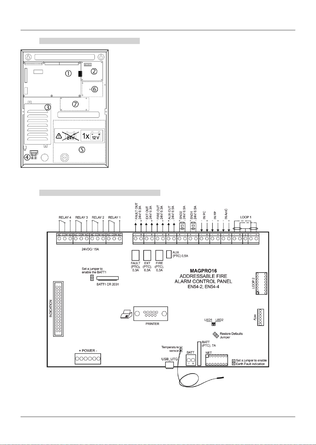
2.2.2 Configuration of the basic modules
Figure 6 – Configuration of the modules in the box:
1 – Main PCB (control panel)
2 – Second loop controller (optional, it may not be present in your
system configuration)
3 – Power supply unit
4 – Terminal 230V for connection of the main power supply cable
5 – Place for accumulator battery, 1 х 12V/ 18Ah
6 – Place for mounting of AJAX LAN communication module
7 – Place for mounting of redundant network module
2.2.3 Description of the main PCB (control panel)
Figure 7 – Main PCB of the MAGPRO16 fire alarm panel
11
Page 12
MAGPRO16 Addressable Fire Alarm Panel – Installation and Programming Manual
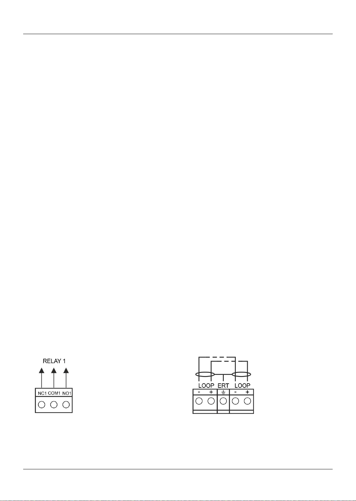
Figure 8 – Internal structure
of relay output
Figure 9 – Connection to the
loop controller
Description of the terminal row (left to right):
RELAY 1 - 4 – Programmable volt free change over relay contacts each, 24VDC@15A. Each relay has one
NO (normal open) and one NC (normal closed) contact with common lead on a terminal. When a relay output
is activated the NO contact is closed and the NC contact is opened.
FAULT – Potential, monitored output for connection of auxiliary devices, 24 VDC/ 0.3А. This output is
deactivated in case of system trouble or fault.
EXT - Potential, monitored output for fire extinguishing, 24 VDC/ 0.3А. This output is activated in case of a fire
alarm condition.
FIRE – Potential, monitored output for connection of auxiliary devices (signaling devices for example), 24 VDC/
0.3А. This output is activated in case of fire in the premises.
AUX – Potential output for power supply of auxiliary devices, 24 VDC/ 0.5А.
SND 1, SND 2 – Potential, monitored outputs for connecting sounders, 24 VDC/ 0.5А.
IN PC (Input Protection Alarm Confirmation) – Input for monitoring of signal „Confirmation for extinguishing
started in the site“ sent by extinguishing control panel.
IN FP (Input Fault Protection Panel) – Input for monitoring of signal „Fault“ sent by extinguishing control panel.
IN AmC (Input Alarm Confirmation) – Input for monitoring of signal „Alarm confirmation“ sent by extinguishing
control panel.
LOOP 1 (-LOOP+ / +ERT / -LOOP+) – Terminal row for connecting Loop 1 in the system.
LOOP 2 – Interface connector for adding MAGPRO16-L250 loop (for Loop 2) in the system configuration.
INDICATION – Interface connection for the indication module.
POWER – Interface connection for the main power supply unit.
JP7 – Jumper for enable/ disable the built-in battery for supporting the real time clock in case of main and
backup power supply failure.
PRINTER - RS232 interface connector for heat-printer.
USB UTG – Micro USB A/B connector for firmware update of the main microprocessor via PC or USB flash
drive; suitable also for programming via MAGPRO programming software.
BATT – Connector with wires (red and black) for connection to the accumulator battery. The type of connection
is according the battery terminals – to every cable shoe is added a separate cable lug connector Ø5mm (M5).
Restore Defaults – Jumper for full hardware reset of the panel and restoring the factory default settings.
Earth Fault – Jumper for enable/disable indication for earth fault.
Example: If you want to enable the earth fault indication set a jumper on Earth Fault terminals.
NET – Interface connector for a redundant network module to the system configuration.
Ajax – Interface connector for adding of AJAX LAN communication module to the system configuration.
Fuses:
AUX – 0.5А, PTC type, resettable
FAULT, EXT, FIRE – 0.3A, PTC type, resettable
BATT – 7A, PTC type, resettable
LED indication:
LED 1 (red) – Indication for scanning the devices connected to Loop1. In normal operation mode the LED
lights on continuously in 10 seconds intervals.
LED 2 (green) – Indication for data transfer between the main microprocessor of the panel and the controller
for Loop 1.In normal operation mode is constantly blinking.
Temperature sensor:
The temperature sensor is used for measurement of the battery temperature. The sensor is mounted at the end of the
wires couple factory connected to “Temperature sensor” terminal on the panel’s PCB.
The temperature sensor should be places behind or under the accumulator battery.
12
Page 13
MAGPRO16 Addressable Fire Alarm Panel – Installation and Programming Manual
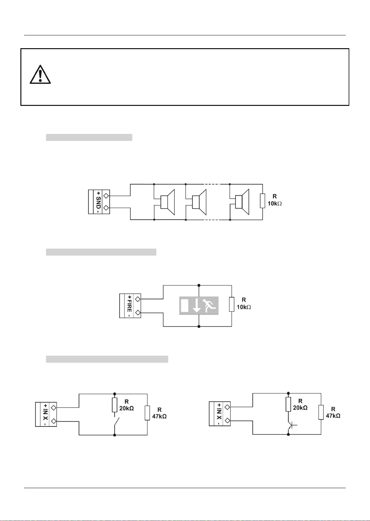
The monitored outputs SND, at activation, provide 24VDC@0,5A to the load connected between
them and GND*.
The monitored outputs FAULT, EXT and FIRE, provide 24VDC@0,3A to the load connected
between them and GND*.
It is necessary to connect in parallel to the last device in the loop a 10k terminate resistor,
so to ensure that the panel is able to detect any break or short circuit in the loop – see Figures 10
and 11!
Sounder 1
Sounder 2
Sounder N
а) Connecting diagram of relay
contact to the input
b) Connecting diagram of open
collector to the input
2.3. Connection of Signaling Devices
* The grounding point of the panel.
2.3.1 Connecting of Sounders
To every monitored output SND could be connected several sounders - Figure 10. The maximum number of sounders
that could be connected in the circuit depends on their total current consumption, which must not exceed 0,5A.
Before connecting the last sounder in the circuit, parallel to it must be added resistor 10k.
Figure 10 – Connecting sounders to SND output
2.3.2 Connecting of Signaling Devices
To every monitored output FAULT, EXT and FIRE could be connected signaling and other control devices – Figure 11.
The maximal consumption of the devices should not exceed 0.3А.
Before connecting the last device in the circuit, parallel to it must be added resistor 10k.
Figure 11 – Example for connecting of end device (an illuminated exit sign) to the Monitored FIRE Output.
2.3.3 Connecting to the Specialized Inputs
The specialized inputs of MAGPRO16 fire alarm panel are designed for operation with an extinguishing control panel.
The example connection diagrams are presented on Figures 12 а) and b).
Figure 12 – Examples of connections to the specialized input IN XX
13
Page 14
MAGPRO16 Addressable Fire Alarm Panel – Installation and Programming Manual
Detector 1
Detector 2
Detector N
MAGPRO16
Main Board
MAGPRO16-L250
Loop controller
2.3.4 Loop Controller
The MAGPRO16 fire alarm panel supports operation with MAGPRO16-L250 loop controller via communication protocol
MAGPRO.
The Loop Controller realizes the connection between the I/O Module and devices connected to the communication
line. The Loop Expander has two basic functions:
Gathers data from the devices in the communication line and transfers it to the main microcontroller;
Receives commands from the main microcontroller and transfers them to the devices connected in the
communication line.
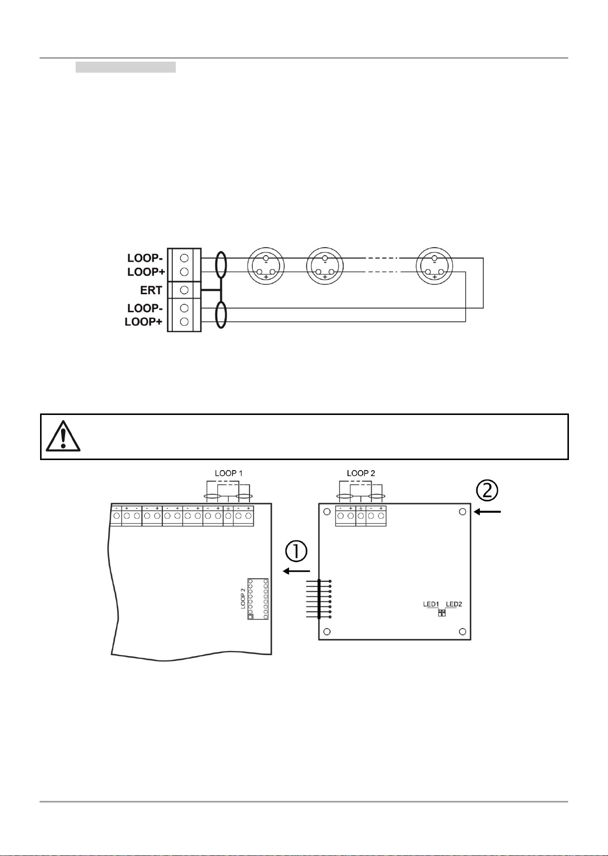
Up to 250 MAGPRO devices can be connected to MAGPRO16-L250 loop controller. The general connection
diagram of devices to the loop controller is shown on Figure 13.
The maximum current consumption of the devices in the communication line is Imax = 500mA. If the consumption
exceeds this value an over-load protection would be turned on.
Figure 13 – Connecting of detectors to a loop controller
In the configuration of addressable fire alarm panel MAGPRO16 could be mounted a second loop controller as a
separate module – see Figure 14.
ATTENTION! Do not add or remove loop expanders to the fire panel configuration when
the main and backup power supplies are on!
- Connect the connectors: LOOP 2 of the main control panel and LOOP of the second loop controller.
- Fix the second loop expander to the metal box of the fire panel using the supplied bolts in the spare parts
kit.
LED 1/ LED 2 – LED indication for the loop controller status, analogical to that for the main control panel – see
the description on page 12.
Figure 14 – Adding of second loop controller MAGPRO16-L250 Loop
14
Page 15
MAGPRO16 Addressable Fire Alarm Panel – Installation and Programming Manual
1. To ensure the ability of the fire
panel to receive the signals from the
devices in the loop, calculate:
L
C1max
≤ 123 / R
C
2. To ensure the ability of the fire
panel to recognize the double
addresses in the system, calculate:
L
C2max
≤ 62 / RC
3. To ensure the ability of the devices
in the loop to receive command
signals from the panel, calculate:
L
C3max
≤ (12 / Imax - Ri) / RC
2.3.5 Maximum Permissible Cable Length
The maximum length of the loop in the system could vary according to the cross-section and the ohmic resistance of
the used cable.
ATTENTION! MAGPRO16-L250 Loop controller supports up to 250 devices, regardless of the type!
To ensure the correct operation of the system is necessary to make some calculations in advance:
where:
L
R
, L
C1max
- is total ohm resistance of the two wires of the used able; its value shows the magnitude of the cable resistance at
C
C2max
, L
- are maximum permissible length of the used cable, [km];
C3max
length 1km [Ω/km];
R
- is the total resistance of the isolator modules in the loop;
i
I
- is the maximum current consumption in the loop - total amount of the current consumption of all devices in the
max
loop *.
*Note, In case of using one or more from the following devices MAGPRO Series: SD1, HD1, HSD1, CP, CZM, WS,
WSS, DBS, DBSS.
Then the total amount for I
includes: the maximal current consumption in alarm mode of these 15 devices with
max
highest consumption, and for the rest of the devices - the total consumption in stand-by mode.
L
- is the necessary length of the cable for the loop.
C
After calculating, the maximal length of the cable is determined according:
• If L
≤ L
C
C2max
and L
≤ L
C
- the fire pane will be able to communicate with the devices in the loop and
C3max
also will be able to identify the presence of double addresses.
• If L
C2max
< LC ≤ L
C1max
and L
≤ L
C
- the fire panel will be able to communicate with the devices in
C3max
the loop but will not be able to identify the presence of double addresses.
ATTENTION! Always calculate the maximal cable length according the mentioned above formulas!
If L
> L
C
C1max
or L
> L
C
- the fire panel would not be able to communicate with the devices.
C3max
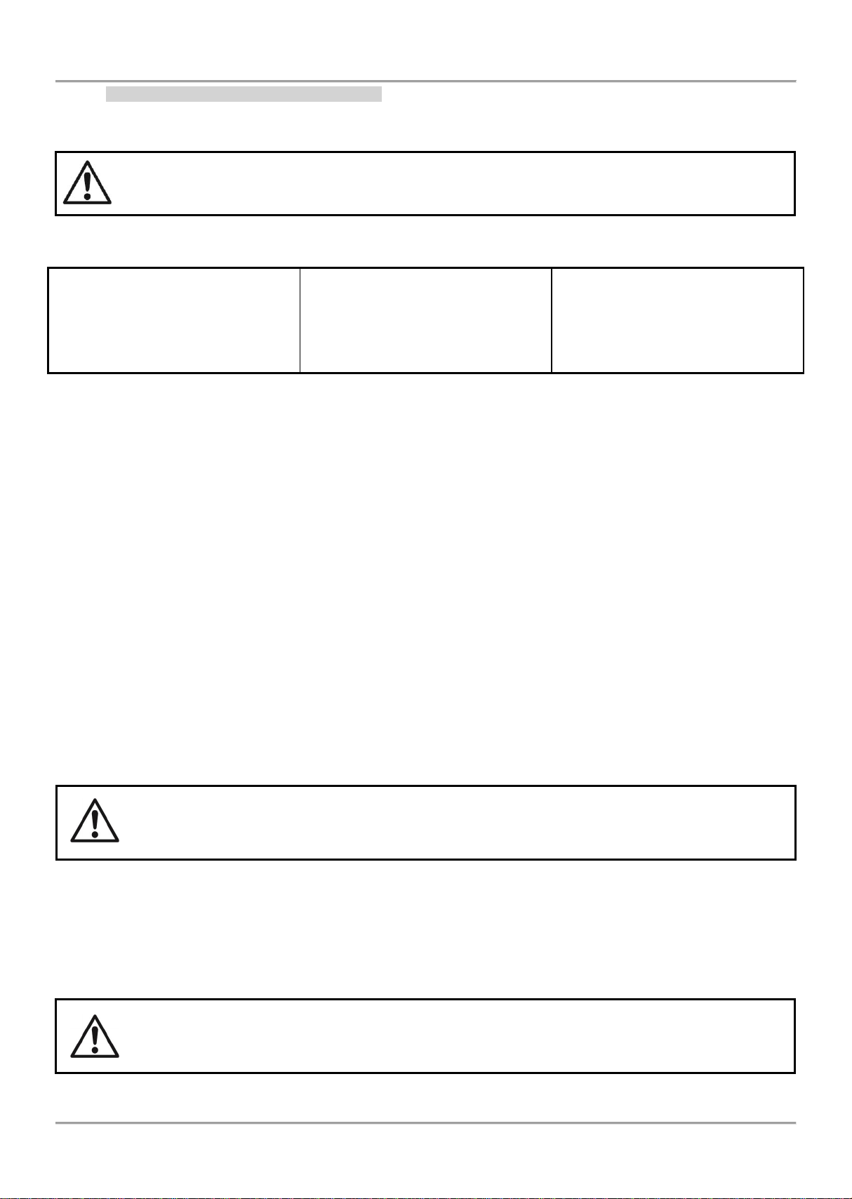
The connection diagram shown on Figure 15, gives the possibility to protect devices against opening and short circuit.
For example, short-circuit in section 2 will not influence the operation of sections 1 and 3. The isolator modules at the
both ends of section 2 will isolate it, and section 1 and 3 will continue working properly, as section 1 will operate by
supply from the channel “A” and section 3 - by supply from channel “B”. Since the fire panel will not be able to
communicate with the devices from section 2, it will generate an alarm signal for lost devices and open circuit.
The maximum recommended number of devices between two isolator modules (module isolator
device or using the built-in module isolator in a device) is 30!
15
Page 16
MAGPRO16 Addressable Fire Alarm Panel – Installation and Programming Manual
Device with isolator
Device with isolator
Section 1
Section 3
Section 2
Channel А
Channel В
Main
Power
Source
Fuse 4А
Type: glass time-delay
MAGPRO16
Main Board
Figure 15 – Example for connecting of detectors and call points to a loop expander
(the built-in in the main control panel or MAGPRO16-L250 Loop)
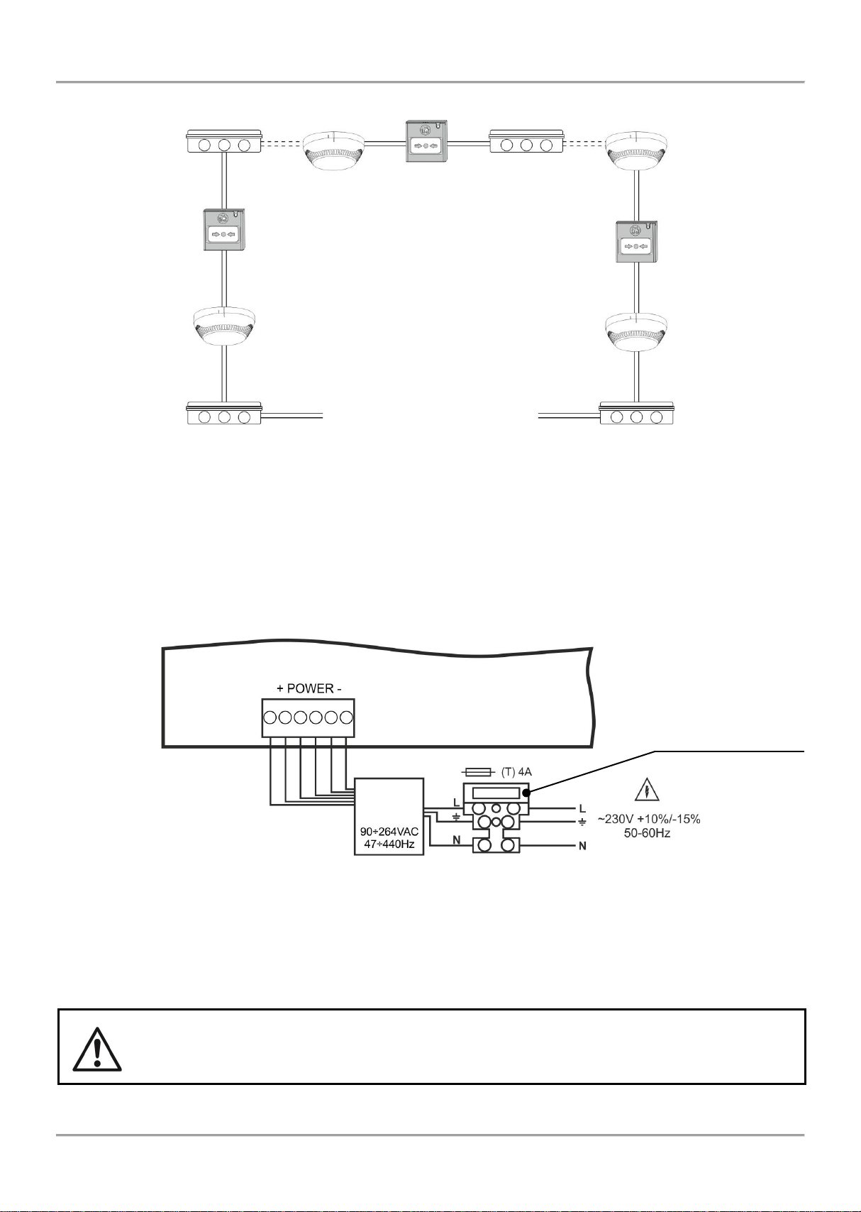
2.4. Connecting to the Main Power Source
The mains power supply of MAGPRO16 fire alarm panel is realized with connection of the main power cable to the
230V terminal, mounted in the metal box under the powers source. The connection between the 230V terminal and the
main power source is done from the manufacturer. The connection of the main power supply cable to the 230V
terminal is shown on Figure 16.
Before the mains supply is switched on, check the correct connection of each loop, sounder or any other input
or output!
2.5. Connecting the Accumulator Battery
The accumulator battery leads are mounted on a terminal at the bottom of main control panel. Connect the battery
leads to the accumulator terminal as observe the polarity - see Figure 17.
The battery cannot power up the panel before the mains supply has been switched on!
The charging of the accumulator battery is done at maximum current I = 2A and charging voltage U
≤ 13.65V.
Figure 16. Connecting the main power supply cable to the 230V terminal
16
Page 17
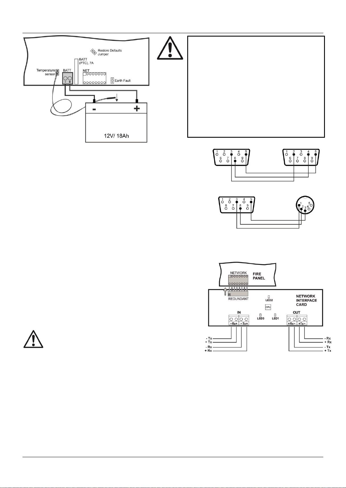
Attention: The connection between the
accumulator battery and the main power
source has some special features.
It is strongly recommended to use only
battery with electrical characteristics and
dimensions pointed from the manufacturer.
Before connecting to the power source
check the polarity of the battery. Connect the
battery after the mains supply is turned on.
If the battery is new it will take a few hours
before its complete charging!
Black
Red
Accumulator
Battery
Figure 17. Connecting
the accumulator battery
MAGPRO16
Main Board
To control panel
To Kafka printer
Figure 18
Figure 19
DB9
DB9
DB9
DIN5
Attention: The connection between the
accumulator battery and the main power
source has some special features.
It is strongly recommended to use only battery
with electrical characteristics and dimensions
pointed from the manufacturer.
Before connecting to the power source check
the polarity of the battery. Connect the battery
after the mains supply is turned on.
If the battery is new it will take a few hours
before its complete charging!
To measure the current temperature of the
battery, place the temperature sensor behind
or under the battery.
2.6. Connecting a Heat Printer
The addressable fire alarm panel MAGPRO16 is equipped with RS232
interface connector, situated in the middle of the main PCB, for
connecting a heat printer. The heat printer allows the technician to print
the log file for the alarm and fault events, warnings and changes during
programming. The capacity of log file is 10 240 events, which are
saved with date and time of occurring – see also item 7.1.4.
The addressable fire alarm panel MAGPRO16 supports Canon 9 type
external printers, models Kafka and Datecs. For connecting the
MAGPRO16 panel to the heat printer you have to prepare a special
cable for the purpose – connect two male DB9-DB9 (Datecs printer) or
DB9-DIN5 (Kafka printer) type connectors as shown on Figure 18.
Before printing (access levels 2 and 3) make sure that the heat printer
is connected to the ‘PRINTER’ interface connector on the main PCB
and the printer is powered on.
2.7. Connecting a Network Interface Card (MAGPRO-NIC)
The addressable fire alarm panel MAGPRO16 is designed with option
for connection in a Ethernet network with other MAGPRO16 or
MAGPRO96 addressable panels (up to 32). The network interface
card is mounted under the main PCB and is connected to ‘NET’
connector – Figure 19. The card should be fixed with screws to the
metal bottom. The maximum cable length between two network
interface cards is 1000m.
Attention: NEVER add or remove the network interface
card to the fire panel configuration WHEN THE MAIN
AND BACKUP POWER SUPPLIES ARE ON!
2.8. Connecting an AJAX LAN Communication Module
The addressable fire alarm panel MAGPRO16 is designed for monitoring via serial interface connection using
specialized AJAX communication module. The monitoring could be realized over LAN network, according the type of
the used module. The communication module is mounted on the place under the second loop controller and it is fixed
with suitable screws to the metal bottom. The connection is realized with interface flat cable between the ‘AJAX’
connector on the main PCB and the interface connector on the communication module itself.
Attention: NEVER add or remove the communication module to the fire panel configuration WHEN THE MAIN
AND BACKUP POWER SUPPLIES ARE ON!
MAGPRO16 Addressable Fire Alarm Panel – Installation and Programming Manual
17
Page 18
MAGPRO16 Addressable Fire Alarm Panel – Installation and Programming Manual
MAGPRO16
Main Board
MAGPRO
Programming
Software
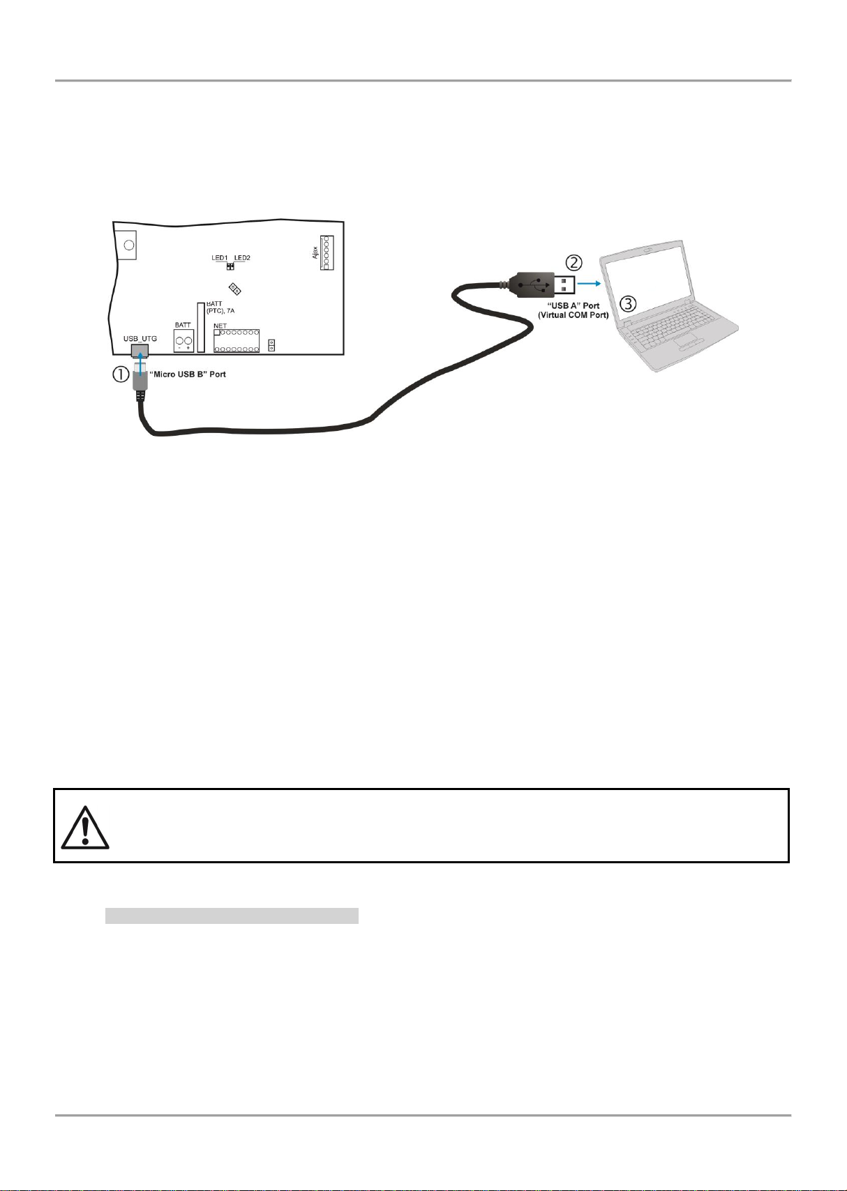
3. PROGRAMMING TYPES
3.1. Programming via MAGPRO Programming Software
The specialized MAGPRO programming software is designed for programming of MAGPRO16/ 96 fire alarm panels.
To program the fire alarm panel MAGPRO16 you should first to install the MAGPRO programming software on your
computer.
To program the MAGPRO16 panel you have to use cable type USB Micro B - USB A – Figure 20.
Figure 20. Programming via MAGPRO programming software
3.2. Programming via Panel’s Keyboard
The addressable fire alarm panel MAGPRO16 can be programmed directly using the keyboard on the front panel. The
programming and settings are accessed from levels 2 (Maintenance) and 3 (Installer). The buttons on the front panel
are organized in three main groups
Functional digit buttons – used for entry in submenus, changing parameter status, entering of new combination
for Maintenance and Installer access codes.
Navigation buttons – arrows for moving the cursor on the screen and switching over the editable fields,
confirmation of entered parameters, cancelation of entered parameters and step back in the menu
programming structure.
Specialized buttons for User operation – Silence buzzer, Silence sounders, Reset, Evacuation, General test of
the LEDs, buzzer and screen.
The detailed description of all buttons on the front panel is presented in item 2.2.1 – 5, page. 9
The detailed description of Maintenance and Installer programming access levels is presented in item 5.
3.3. Firmware Update
ATTENTION!
The firmware update of the main microprocessor of fire alarm panel MAGPRO16 should be
performed by qualified personnel only and after held training program by distributer or
manufacturer!
3.3.1 Firmware Update from Computer
To start a firmware update from a computer you should first to have a copy of an image update file (with *.bin
extension) saved on your computer. For firmware updates use the USB_UTG connector on the main PCB:
Connect the panel to the computer using USB cable: Normal A to Micro B type.
Enter access code for level 2 or 3 and choose menu 9) SOFT. REVISION.
Wait for the message from Windows Explorer for found new Removable Disk.
The panel will display automatically on the screen:
USB Host Detected
1. Copy image file to Removable Disk
2. Make Eject at Removable Disk
> Panel is configured
18
Page 19

MAGPRO16 Addressable Fire Alarm Panel – Installation and Programming Manual
Use the Windows Explorer file manager to copy the new image update file (with *.bin extension) in Removable
Disk directory.
When the copying of the image file completes, remove the Removable Disk, as select Eject option from its
dialogue box (right click with the mouse over it).
If the data in the image file are correct, the panel starts the firmware update procedure of the main
microprocessor accompanied with short beeps.
Disconnect the USB cable.
The panel will reset itself automatically after a successful firmware update.
3.3.2 Firmware Update from USB Drive
To start a firmware update from a USB drive you should first have to copy the new image update file (with *.bin
extension) in the main directory of the USB removable disk. The name of the file must be short – up to 8 symbols.
Connect the panel to the computer using USB cable: USB Micro А - USB A type.
Enter access code for level 2 or 3 and choose menu 9) SOFT. REVISION.
Connect the USB drive, with the new image file (with *.bin extension).
Notes:
1. The panel will scan the files copied only in the main directory and these files in the first subfolders in the tree
hierarchy of the USB drive.
2. It is obligatory the name of the file to be up to 8 symbols long.
Wait until the polling procedure is complete - USB drive will be displayed with its name and manufacturer. On
the last row of the screen will start blinking the notice Push 'Enter' to continue.
Press Enter button and wait for a message for the USB drive capacity. On the last row of the screen will be
active two buttons (2) To Panel and (3) From Panel.
Press (2) To Panel button. A list with the present image files (with *.bin extension) copied to USB drive is
displayed on the screen, as the software revision is displayed on the right side, for example:
0:/MAGPRO16/MAGPRO162_0.BIN v 2.00
Scroll through the listed files using the buttons with up and down arrows – the currently selected file is blinking.
Select the file and press Enter button.
The panel starts uploading the file from the USB drive to the external Flash memory of the panel. The running
process is displayed with a progress bar.
If the data in the image file are correct, the panel starts the firmware update procedure of the main
microprocessor accompanied with short beeps.
Disconnect the USB cable.
The panel will reset itself automatically after a successful firmware update.
3.3.3 Copying Image File from the Panel to USB Drive
Connect the panel to the computer using USB cable: USB Micro B - USB A type.
Enter access code for level 2 or 3 and choose menu 9) SOFT. REVISION.
Connect the USB drive.
Wait until the polling procedure is complete - USB drive will be displayed with its name and manufacturer. On
the last row of the screen will start blinking the notice Push 'Enter' to continue.
Press Enter button and wait for a message for the USB drive capacity. On the last row of the screen will be
active two buttons (2) To Panel and (3) From Panel.
Press (3) From Panel button – the panel will download a copy of its own image file to the USB drive and saves
the file in MAGPRO16 folder.
4. FULL HARDWARE RESET
The full hardware reset of MAGPRO16 addressable fire alarm panel allows the engineer to restore all factory settings
and access code combinations for level 2 (Maintenance) and 3 (Installer).
To perform full hardware reset, follow the steps:
1. Disconnect the mains and backup power supplies.
2. Set a jumper on ‘RESTORE DEFAULTS’ terminal on the PCB.
3. Connect mains and after that the backup power supply.
4. Wait the procedure for initialization to complete.
5. Remove the jumper from ‘RESTORE DEFAULTS’ terminal.
6. Proceed with save system configuration and other settings.
19
Page 20
MAGPRO16 Addressable Fire Alarm Panel – Installation and Programming Manual
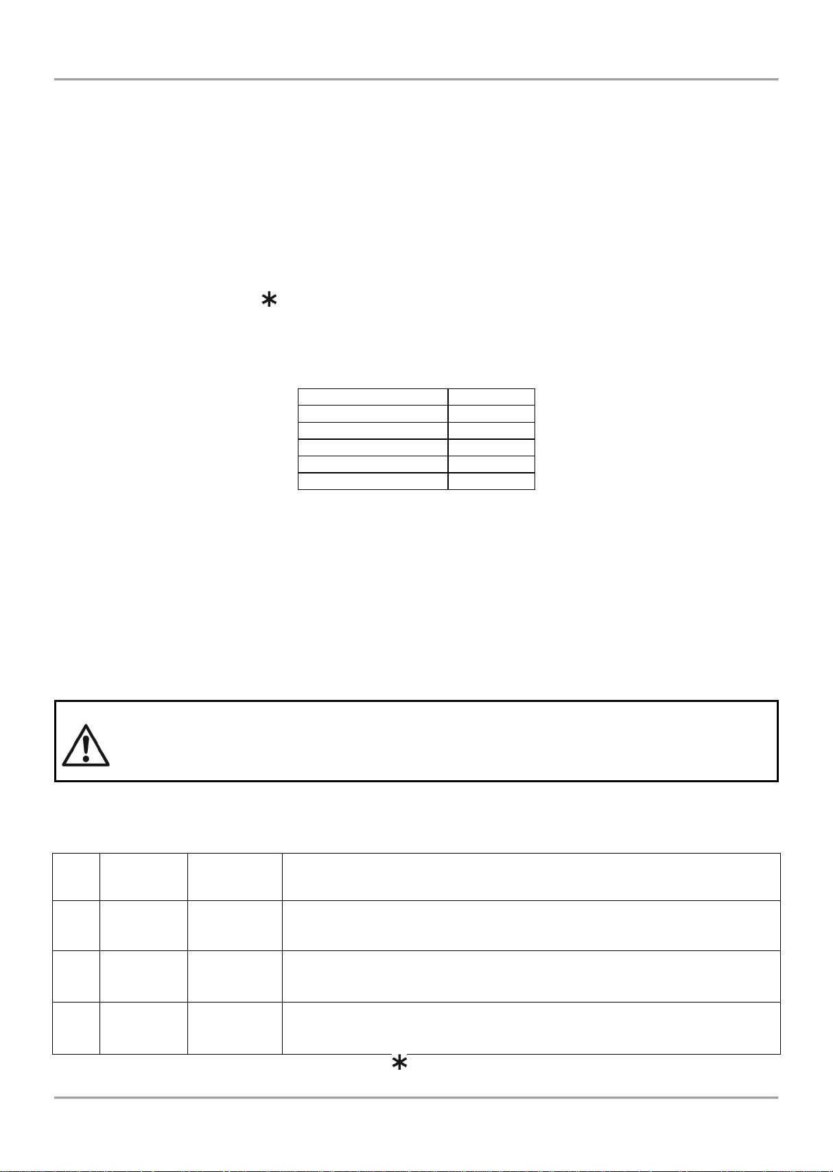
Indication - Groups
Priority
ALARMS
The highest
FAULTS
High
DISABLEMENTS
Normal
TESTS
Normal
WARNINGS
Low
Level
Description
Code
Combination
Access
1
User
-
Only Silence buzzer and Evacuation* buttons are active. It is not allowed to
enter Maintenance and Programming access levels.
* Just for that cases, when the fire alarm signal is received from a device
2
Maintenance
2222
Silence buzzer, Silence sounders, Reset and Evacuation buttons are active.
Maintenance access level entry, which allows partial programming and menu
settings.
3
Installer
3333
Silence buzzer, Silence sounders, Reset and Evacuation buttons are active.
Installer access level entry, which allows full programming and settings.
5. PROGRAMMING OF MAGPRO16 FIRE ALARM PANEL
5.1. General Information for Programming and Operation
Addressable fire alarm panel MAGPRO16 can be programmed directly through the navigation and functional digit
buttons on the front panel. The programming menus are organized in a text tree-structure and are viewed on the LCDdisplay (4 rows x 40 symbols). The access to the programming menus is organized in three levels – see items 5.2.
When turned on, the panel always runs a procedure of loading the parameters, which usually takes about 5-6 sec.
There is no access to the menus of the panel during that procedure.
Upon the initial startup, the panel does not hold any configurations. Initialization may take several minutes. The
initialization time needed depends on the number of periphery and loop devices – for Loop 1 and Loop 2. After the
panel has been turned on, it performs a procedure for detecting newly installed loop devices – see also APPENDIX C,
page 48.
During the procedure the symbol “ ” is blinking in the up right corner of the screen. This symbol will appear always
when running similar procedures like resetting of devices or recognized new devices connected to the loop.
Right after the initial startup of the mains power supply and initialization completed the panel turns to normal operation
mode. If there are any active alarm and fault messages they are displayed on the screen, as the indication follows the
priority:
The name of the current active indication group is blinking together with the number of the first message. Press the
ENTER button to review some additional information for the respective message as data and time of occurring, device
address, zone number or other, according the trouble type.
The indication for the active ALARMS in the system is viewed with highest priority.
The addressable fire alarm panel MAGPRO16 supports different languages for the programming menus.
The factory default setting of the language is in English. You can change the language after the initial powerup as enter in sequence:
Press CANCEL – enter code 3333 – select menu 6) GENERAL SETTINGS – menu 6.4) PANEL SETTINGS –
Button 1 – Button ENTER
Use the ENTER button to enter in programming menus and confirmation of entered values and
parameters; the functional digit buttons are used for entering of access codes and changing the
current status; the navigation buttons (up/ down and left/ right arrows) are used for scrolling
through the menus and for changing the editing field.
5.2. Codes and Access Levels
There are three access levels in MAGPRO16 panel: User, Maintenance and Installer. Every level comprises different
functions and operations. To enter Maintenance and Installer levels is necessary to enter valid access code:
The introduced code combinations are visualized with “ “ symbol. The entry is automatic.
20
Page 21

MAGPRO16 Addressable Fire Alarm Panel – Installation and Programming Manual
Mode/ Menu
Description
Access Level
1 2 3
Operation modes
ALARMS
Viewing the Alarms Messages in the system.
FAULTS
Viewing the Faults Messages in the system.
DISABLEMENTS
Viewing the active disablements in the system.
TESTS
Viewing the running tests in the system.
WARNINGS
Viewing the Warnings Messages in the system.
Silence buzzer
Deactivating Internal Buzzer.
Silence Sounders
Deactivating the Sounders.
During active fire alarms and deactivated/ silenced
sounders the LED next the button is lighting up.
Reset
Resetting the panel without switching off the main and
backup power supplies.
Evacuation
Activating Evacuation alarm signal; the sounders will
activate immediately overriding all introduced delays.
*
Test
General test for operability of all LEDs and internal buzzer.
Programming menus
View history LOG
Viewing the LOG file for all events; printing of all or
separate events; clear the log file.
Zones
Zones status; setting a zone name; parameter
programming; zone test for operability.
Device Setup
Setting a device name; parameter programming.
Addressing:
Menus for addressing devices.
-
Set address
Setting an address for single devices.
Change address
Changing device address.
Self-addressing
Automatic self-addressing mode.
Panel outputs
Parameter programming for the built-in panel outputs:
SOUNDERS, EXTINGUISHING, FIRE, FAULT, RELAY
OUTPUTS.
General Settings:
General settings common for the panel.
-
Access codes
Changing the code combinations for levels Maintenance
and Installer; enable/ disable the automatic exit from the
installer programming menus.
Time/ Day
Setting the current time and date.
Day/ Night alarm mode
Setting Day/ Night alarm mode or operation on schedule.
Panel settings
Changing the menu language, setting the backlight
brightness; entering disablements.
Delay Т1
Setting the Delay Т1.
Sounders mode
Programming the operation of SOUNDER outputs.
Save configuration
Saving the set system configuration.
Restore defaults
Restoring the factory default settings.
Software revision
Reviewing the current software revision.
Network
Setting the redundant network parameters
Active isolators
Reviewing the activated isolators in the system.
Access level 1
Return to Access Level 1.
The access codes could be changed only from level Installer - menu 6) General Settings - submenu 6.1) Access
codes.
There are different restrictions on the panel functions in the relative access levels, which are shown in the table below:
* Just for that cases, when the fire alarm signal is received from a device
- The operation modes and the menus are not supported for that access level
- The operation modes and the menus can be reviewed or are allowed for partial programming for that access level.
21
Page 22

MAGPRO16 Addressable Fire Alarm Panel – Installation and Programming Manual
6. DESCRIPTION OF THE OPERATION MODES
In this section you can find detailed descriptions of all operation modes of MAGPRO16 addressable fire alarm panel.
The modes for reviewing of system events are accessible only from level 1 without entering access code. If no alarm,
fault or warning messages, active tests and disablements are present, then the panel is in normal operation mode and
only the current day and time are displayed. In case of alarm, fault or warning situation is occurred the panel will
display information and text messages for the events. A list of all types of event messages is presented with details in
APPENDIX A, page 46.
6.1. Review of Alarm Events
The messages for alarm events are displayed with the highest priority in the system. In case of alarm in the system the
panel will show a list with active alarms at the moment, and ALARMS mode is blinking together with the number of the
first alarm message. Over the button (1) is displayed the total number of the active alarms. The LED ‘General Fire’
lights on together with the number of the zone in alarm. The panel is signaling with continuous sound signal, which can
be stopped with pressing the ‘Silence buzzer’ button. The activated sounders could be stopped after entering access
level 2 or 3 and pressing the ‘Silence sounders’ button.
Example:
The User can review also some additional information for every of the alarm events. For this, select the number of the
alarm message using up/ down arrow buttons (the number of the selected event is blinking) and press ENTER button.
On the screen is displayed information for the loop number and the address of the device sensed the alarm event. At
the bottom of the screen is displayed the day and time of occurring of the respective event. Note that the additional
information is different according the type of the alarm event. To exit the review alarm events mode, press CANCEL
button.
6.2. Review of Fault Events
The messages for fault events are displayed with high priority. If no alarm events are present, and there are active
faults in the system, the FAULTS mode is blinking together with the number of the first fault event. The LED ‘General
Fault’ lights on. The faults messages are cleared automatically after the fault condition is restored.
Example:
The User can review also some additional information for every of the faults events. For this, select the number of the
fault message using up/ down arrow buttons (the number of the selected event is blinking) and press ENTER button.
In case, there are active alarms in the system, but you want to review the fault messages, press button (2) – FAULTS
mode. The present faults in the system are displayed with serial numbers. The reviewing is the same as described in
item 6.1. The total number of active faults is displayed at the bottom right corner of the screen. Use button (1) to go
back to ALARMS mode and reviewing the alarm messages.
To review the FAULTS at active alarms in the system:
To exit the review fault events mode, press CANCEL button.
22
Page 23

MAGPRO16 Addressable Fire Alarm Panel – Installation and Programming Manual
6.3. Review of Disablements
The messages for disablements are displayed with normal priority. If no alarm or fault events are present, and there
are active disablements in the system, the DISABLEMENTS mode is blinking together with the number of the first
disablement. The LED ‘Disable’ is lighting on.
Example:
The User can review also some additional information for each of the disablements. For this, select the number of the
disablement message using up/ down arrow buttons (the number of the selected event is blinking) and press ENTER
button.
In case, there are active alarms and/ or faults in the system, but you want to review the disablements, press button (3)
– DISABLEMENTS mode. The disablements in the system are displayed with serial numbers. The reviewing is the
same as described in item 6.1. The total number of the introduced disablements is displayed at the bottom right corner
of the screen. Use button (1) to go back to ALARMS mode and reviewing the alarm messages.
To review the DISABLEMENTS at active alarms and/ or faults in the system:
To exit the review fault events mode, press CANCEL button.
6.4. Review of Running Tests
The messages for running tests are displayed with normal priority. If no alarm or fault events or disablements are
present, and there are active tests in the system, the TESTS mode is blinking together with the number of the first
running test. The LED ‘Test’ is lighting on.
The numbers of the zones in test mode with activated detectors are blinking.
Example:
The User can review the number of the zone in test mode. For this, select the number of the zone using up/ down
arrow buttons (the number of the selected event is blinking) and press ENTER button.
If, there are active alarms and/ or faults in the system and you want to review the running tests, press button (4)
MORE>> – TESTS mode is blinking. The tests running in the system are displayed with serial numbers. The reviewing
is the same as described in item 6.1. The total number of the running tests is displayed at the bottom right corner of the
screen. Use button (1) to go back to ALARMS mode and reviewing the alarm messages.
23
Page 24

MAGPRO16 Addressable Fire Alarm Panel – Installation and Programming Manual
After choosing the button (2) TESTS the screen displays:
To exit the review of running tests mode, press CANCEL button.
6.5. Review of Warning Messages
The messages for warnings are displayed with low priority. If no alarm or fault events or disablements and tests are
present, and there are active warnings in the system, the WARNINGS mode is blinking together with the number of the
first message. There is no LED indication on the front panel.
Example:
The User can review also some additional information for every warning message. For this, select the number of the
message using up/ down arrow buttons (the number of the selected event is blinking) and press ENTER button. On the
screen is displayed information for the loop number and the address of the device. At the bottom of the screen is
displayed the day and time of occurring of the warning. Note that the additional information is different according the
type of the warning event.
In case, there are active alarms and/ or faults in the system, but you want to review the warnings, press button (4)
MORE>> – (3) WARNING mode. The warning messages in the system are displayed with serial numbers. The
reviewing is the same as described in item 6.1. The total number of the warnings is displayed at the bottom right corner
of the screen. Use button (1) to go back to ALARMS mode and reviewing the alarm messages.
To review the WARNINGS at active alarms and/ or faults in the system:
After choosing the button (3) WARNINGS the screen displays:
To exit the review warning messages mode, press CANCEL button.
NOTE: If you are programming parameters at Access Level 2 (Maintenance) or Access Level 3 (Installer) and there is
an alarm or fault event in the system, the panel will automatically display a list with messages. After reviewing the
events, you can return to the programming mode with single pressing the CANCEL button.
24
Page 25

MAGPRO16 Addressable Fire Alarm Panel – Installation and Programming Manual
Maintenance Code – 2222
Installer Code – 3333
Maintenance Code – 2222
Installer Code – 3333
Maintenance Code – 2222
Installer Code – 3333
6.6. Silencing the Internal Buzzer
The internal buzzer of addressable fire alarm panel MAGPRO16 is signaling in case of activated alarm or fault events
in the system. The buzzer silencing is available from every access level without code entry.
To silence the internal buzzer press button.
6.7. Silencing the Sounders
The sounders silencing is available from access levels 2 and 3 after code entry.
To silence the sounders enter in sequence:
The LED ‘Silence sounders’ right to the button is lighting up.
To reset the panel in normal operation mode press ‘Reset’ button.
6.8. Activate Evacuation
The evacuation alert is available for activation from every access level regarding the following:
Level 1: Just for that cases, when the fire alarm signal is received from a detector in a zone.
To start the sounders for evacuation alert, the user has to press the button.
Levels 2 and 3: In case there is no fire alarm signal from a detector in a zone.
To start the sounders for evacuation alert, the user has to enter in sequence:
6.9. Resetting the Panel
The resetting of the panel’s current state is available from access levels 2 and 3 after code entry. The resetting function
is used for initializing the panel and return to normal operation mode after alarm or fault restoring.
To reset the panel enter in sequence:
After resetting are cleared also all introduced earlier test in zones and disablements. The introduced delays are not
cleared. The panel returns to normal operation mode.
6.10. Indication Test
The indication test could be started at any time regardless of the access level. The general test allows the user to
review the correct operation of the LED indication on the front panel, the sound signal of the internal buzzer, and the
visualization on the LCD display.
To start the general test press button – all LEDs must light on and the internal buzzer starts sounding. On the
LCD module every one position is displayed with 5x8 dots. The panel will automatically exit the general test mode after
6 seconds. The general test can be stopped also with next pressing of the same button.
25
Page 26
MAGPRO16 Addressable Fire Alarm Panel – Installation and Programming Manual
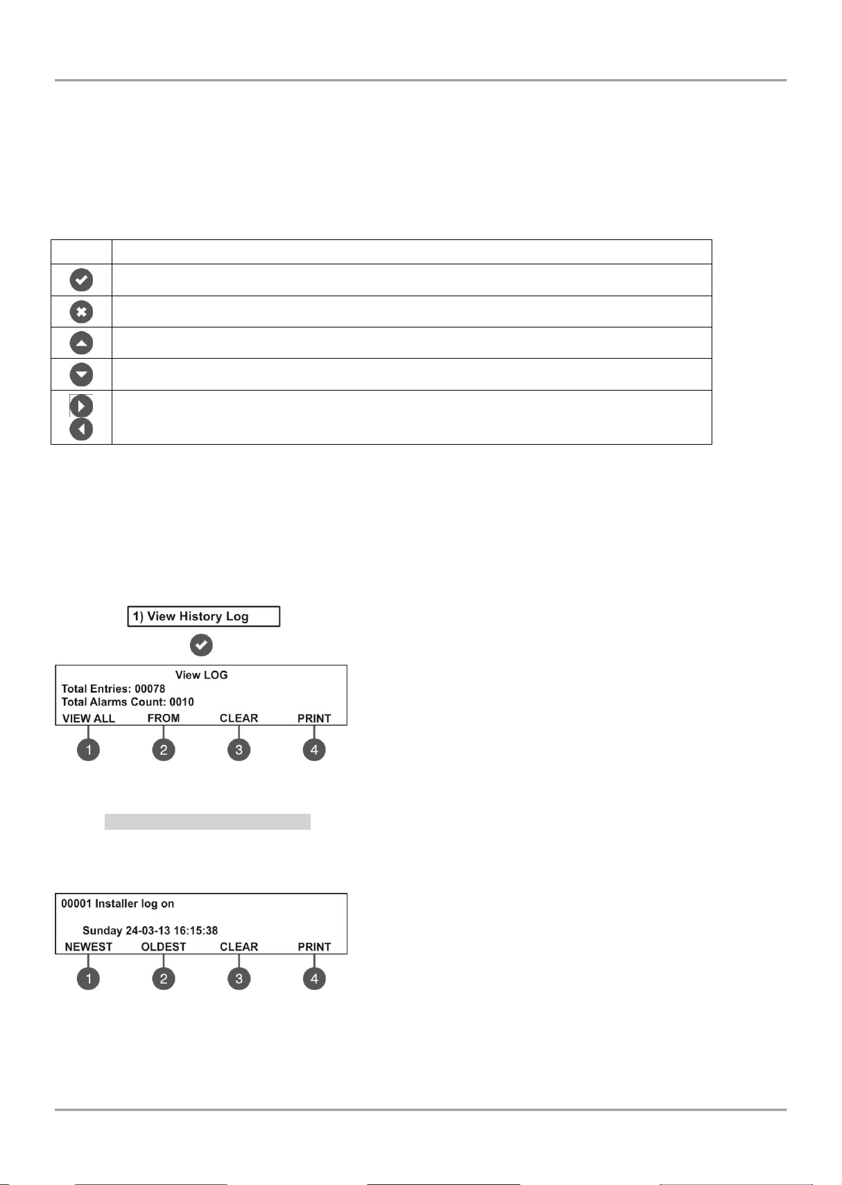
Button
Functions
Menu entry; Confirmation of entered parameters and settings.
Cancelation of entered parameters and settings; Step back in the menu structure.
Scrolling between menus; Increasing values; Text entering.
Scrolling between menus; Decreasing values; Text entering.
Changing the editing fields.
7. DESCRIPTION OF THE PROGRAMMING MENUS
The programming menus are accessible from level 2 (Maintenance) and level 3 (Installer) after entering a valid access
code.
In level 2 could be realized partial programming of parameters, and some values are accessible only for reviewing.
In level 3 could be realized full programming and settings, and also to restore the factory default settings, including
access codes. For details see the descriptions in the tables in item 5.2 for the rights and limitations for every access
level.
The navigation buttons have the following functionalities in operation:
7.1. View History Log Menu
This menu allows the installer to review and print the system events recorded in the panel memory log file. The
capacity of the panel memory log file is 10 240 events. The installer can clear also all panel’s memory or to extract a
list of events by date. The menus are accessible from levels 2 and 3.
After entering the menu the screen displays:
The following general information is displayed in the main screen of
VIEW LOG menu:
Total Entries - Shows the total number of the recorded events in the
memory log file.
Total Alarms Count - Shows the total number of the registered
alarm events.
Use the functional digit buttons to enter the respective submenu.
7.1.1 Review of Full Events List
From the main screen of VIEW LOG menu press (1) VIEW ALL button. The last (newest) event is displayed on the
screen. Use the buttons with up and down arrows to review all recorded events one-by-one, as everyone is displayed
with date and time of occurring.
Press a functional button for entry in the respective submenu:
1 – NEWEST: Shows the last recorded event.
2 – OLDEST: Shows the first recorded event.
3 – CLEAR: See the description of item 7.1.3
4 – PRINT: See the description of 7.1.4
Exit to the main screen of VIEW LOG menu is realized with CANCEL button.
26
Page 27
MAGPRO16 Addressable Fire Alarm Panel – Installation and Programming Manual
7.1.2 Review of List of Events by Date
From the main screen of VIEW LOG menu press (2) FROM button. In “FROM” submenu the installer can extract a list
of events by date. Set in sequence the day, the month and the last two digits of the year. The edited digit is flashing.
Scroll between the fields using the left and the right arrows.
In “From date” field enter the new date using the buttons:
- UP arrow for increasing the number
- DOWN arrow for decreasing the number
- LEFT/ RIGHT arrows for changing the editing field
Then press the ENTER button – at the screen is displayed the first event for the entered date with time.
Exit to the main screen of VIEW LOG menu is realized with CANCEL button.
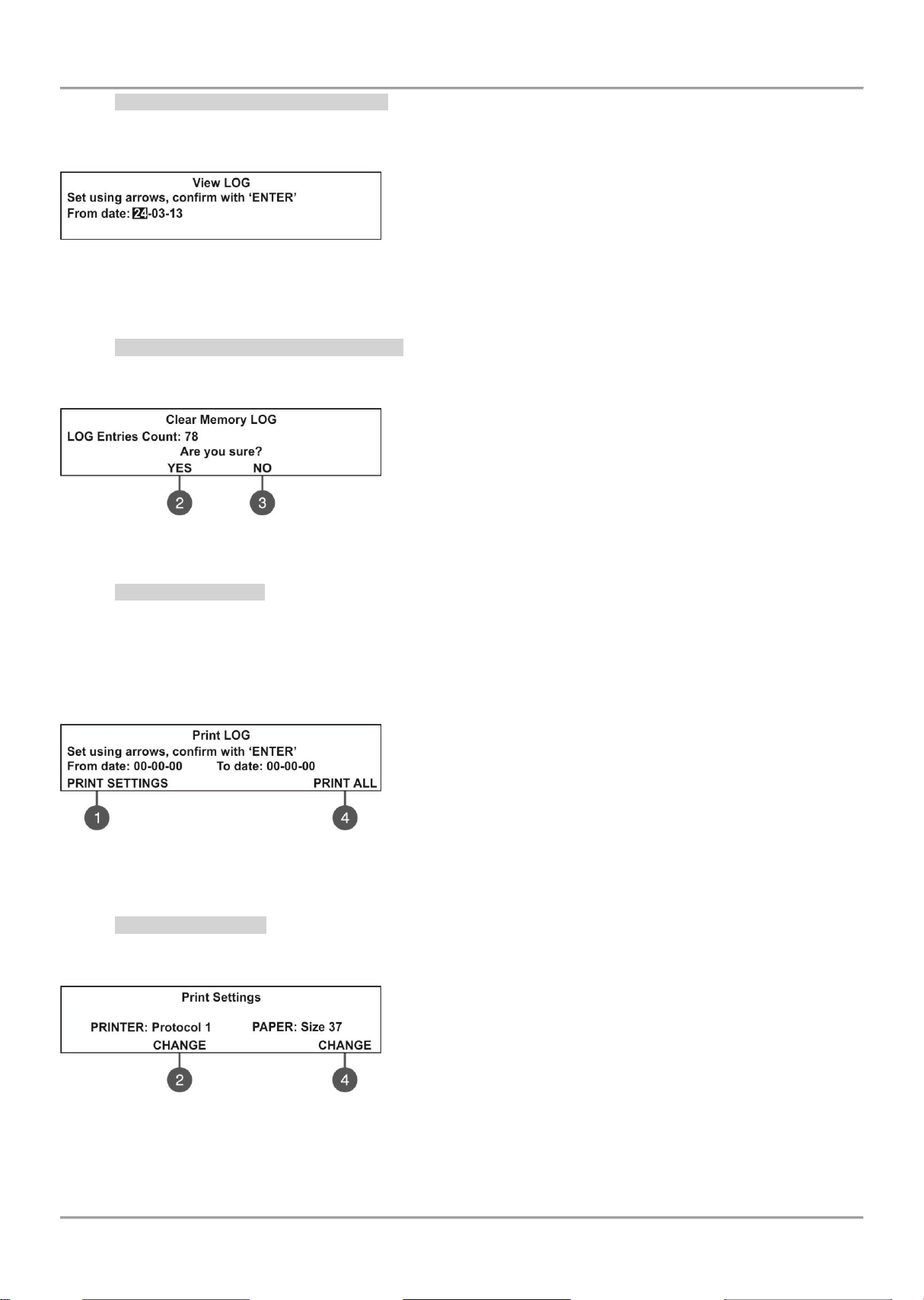
7.1.3 Deleting the Events in the LOG file
From the main screen of VIEW LOG menu press (3) CLEAR button. In “CLEAR”* menu the installer can delete the
entire system events list. The screen displays the total number of recorded events.
The system will ask for confirmation.
To delete all records in the LOG file press (2) YES button.
Exit to the main screen of VIEW LOG menu is realized with CANCEL
or (3) NO button.
Note: The ‘CLEAR’ submenu is not available in the Maintenance access level (2).
7.1.4 Printing Events
Attention: To print the system events you have to connect printer to the ‘PRINTER’ terminal on the main board.
Check your printer connection before entering this menu!
Use only printer models recommended from the manufacturer!
From the main screen of VIEW LOG menu press (4) PRINT button. The screen displays two fields for setting a time
interval for the extract. Two additional submenus for printer settings are available also.
In the fields “From date” and “To date” enter the time interval for
printing. You can use also the functional digit buttons to select:
1 – PRINT SETTINGS. Press to enter in submenu for printer settings
– see also item 1.1.5.
4 – PRINT ALL. Press for direct printing of all recorded events in the
system LOG file.
Press the ENTER button to start printing. The system will ask for confirmation before starting the printing.
7.1.5 Printer Settings
From the main screen of PRINT LOG menu press (1) PRINT SETTINGS. The screen displays the available printer
settings.
Use the respective functional buttons to change the settings of the
respective submenu.
2 – Press the button to change the used printing protocol:
Protocol 1: Kafka printer
Protocol 2: Datecs printer
4 – Press the button to change the size of the used paper. The
possible size formats are: 37/ 57/ 80 mm.
Confirm all changes with pressing ENTER button.
Exit to the main screen of VIEW LOG menu is realized with CANCEL button.
27
Page 28

MAGPRO16 Addressable Fire Alarm Panel – Installation and Programming Manual
7.2. Zones Menu
This menu allows the installer to review and change the status of every zone. In the ‘ZONES’ menus the installer can
test and enable/ disable the zones. Up to 16 zone numbers are available for settings. The currently edited zone
number is blinking. The menu is accessible from levels 2 and 3.
After entering the menu the screen displays:
The screen displays the current status of every zone with its name (if entered). The editable zone number is blinking.
Description of the zone status:
NORMAL – The zone is in normal operation state.
DISABLED – The zone is disabled. See item 7.2.3.
TEST – The zone is in test mode. See item 7.2.2.
FIRE – A device in the zone is in fire.
PRE ALARM – The zone is in preliminary alarm mode. See
the description for ‘2DEVICES’ and ‘DOUBLE’ operation
mode - item 7.2.6.
FAULT – Trouble in the zone – lost device, broken circuit,
etc.
7.2.1 General Submenus
From the main screen of ZONES menu use the functional digit buttons for direct entry to: (1) GO TO and (2) DEV.
COUNT submenus.
Submenu (1) GO TO. Enter the zone number you want to go. After pressing the button the screen displays:
Use up and down arrows to select zone number. Confirm with
‘ENTER’ button. The system will automatically go back to the main
screen of ZONES menu as the number of the zone is blinking.
Submenu (2) DEV. COUNT. The submenu shows information about the total number of the devices in the
respective zone. From the main screen of ZONES menu select a zone number and press button (2). The
screen displays information about the total number of the devices in the selected zone regardless of their
current state.
Example:
Exit to the main screen of ZONES menu is pressing button ENTER
or CANCEL.
7.2.2 Zones Testing
Attention: The zone testing is available only from access level 3!
From the main screen of ZONES menu, select a zone number using the up and down arrow buttons and press button
(3) TEST.
The system will ask for confirmation whether to run the test only for
the selected zone number (button (2) THIS) or for all zones in the
system (button (3) ALL).
The zone(s) status is changed to TEST mode. The LED ‘Test’ is
lighting on permanently.
During the test mode the installer activates detectors in the zone (applies heat or smoke) to check their proper
operation. The panel confirms the receiving of fire alarm messages with short sound signals and the number of the
tested zone is blinking.
To stop the zone test, press the (3) ‘STOP TEST’ functional button. The zone returns to normal operation mode.
After completing the zone testing, reset the panel, as described in item 6.9.
28
Page 29
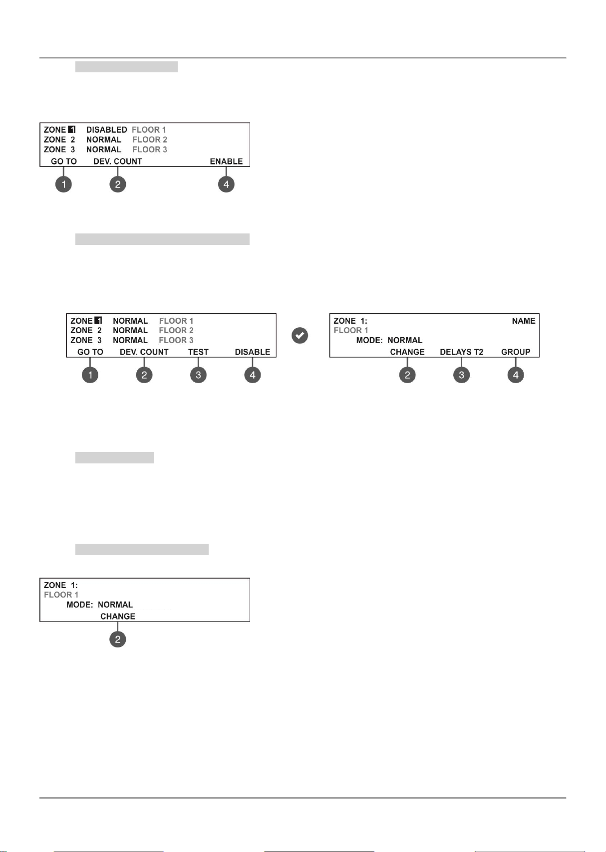
MAGPRO16 Addressable Fire Alarm Panel – Installation and Programming Manual
7.2.3 Disabling Zones
From the main screen of ZONES menu, select a zone number using the up and down arrow buttons and press button
(4) DISABLE. The zone status is changed to DISABLED – the panel stops following the status of the connected
devices to the zone and will not alert for alarms and faults from them. The LED ‘Disable’ lights up permanently.
To enable the zone press the (4) ENABLE button:
Note: If at the moment of enabling the zone, there are activated
devices connected to it (fire alarm or fault condition) the panel will
alert for that immediately!
7.2.4 Programming Zone Parameters
Attention: Programming zone parameters is available only from access level 3!
From the main screen of ZONES menu the User can set additional parameters for every zone in the system. To set
zone parameters, select its number using the up/ down arrow buttons and press ENTER button.
In the new sub screen first you can enter a 40-symbol long name for the zone. Use the functional button to set the
operation mode, delays T2 and a group number.
7.2.5 Zone Name
The User can enter a specific name for the zone after entry in the submenu for zone parameters setting. The name can
be up to 40 digits long and it is entered on the second row. Use the left and right arrows to move the cursor. The
symbols (small and capital letters and characters) are set with the up and down arrows. Confirm the entered name with
ENTER button. See also the APPENDIX B – Table for text and symbols available for zone and device names.
7.2.6 Zone Operation Modes
For a zone can be set one operation mode: NORMAL / 2 DEVICES/ DOUBLE.
Every pressing of button (2) CHANGE will alternatively change the
operation mode of the zone: NORMAL/ / 2DEVICES/ DOUBLE.
The set mode is confirmed with ENTER button.
In NORMAL mode any detector activation within the system generates an alarm event to the respective zone.
In 2 DEVICES mode any detector activation within the system generates a PREALARM event to the respective
zone, but also awaits the activation of another detector from the same zone to generate a FIRE signal. The
RESET command shall disable the FIRE and PREALARM events. If during 5 minutes there is no other fire
alarm signal from other detector in the zone the FIRE alarm will be ignored. The operation of a zone in 2
DEVICES action mode is shown in the examples below.
In DOUBLE mode any detector activation within the system generates a PREALARM event to the respective
zone, but will awaits a second fire signal from the same detector to generate a FIRE signal. The RESET
command shall disable the FIRE and PREALARM events. If during 5 minutes there is no other fire alarm signal
from the same detector in the zone the FIRE alarm will be ignored.
29
Page 30
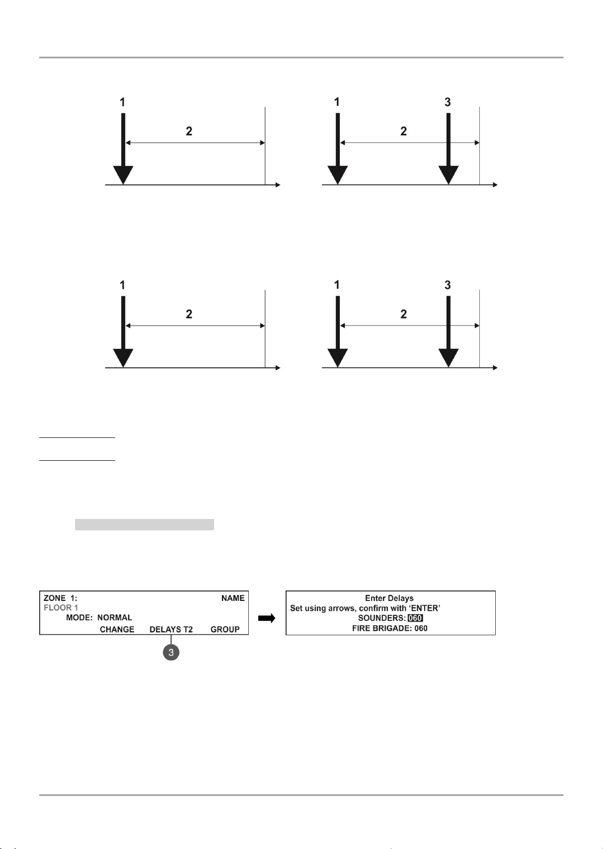
MAGPRO16 Addressable Fire Alarm Panel – Installation and Programming Manual
Time
Time
5 min
5 min
EXAMPLE 1
EXAMPLE 2
D 1
D 1
D 2
Time
Time
5 min
5 min
EXAMPLE 3
EXAMPLE 4
D 1
D 1
D 1
Examples for 2 DEVICES action mode operation:
1 – An incoming alarm signal from Detector 1 and zone reset;
2 – Awaiting for a second alarm signal from other detector in the zone – Pre Alarm Mode;
3 – Second alarm signal from Detector 2 in the zone.
Examples for DOUBLE action mode operation:
1 – An incoming alarm signal from Detector 1 and zone reset;
2 – Awaiting for a second alarm signal from the same detector in the zone – Pre Alarm Mode;
3 – Second alarm signal from Detector 1 in the zone.
EXAMPLES 1, 3: In this case the fire panel will not activate the sounders and the signalization on the front panel
because during time interval 2 no second alarm signal is generated.
EXAMPLES 2, 4: In this case the fire panel will activate the sounders and the signalization on the front panel because
during time interval 2, two alarm signals are generated.
After RESETTING of the panel, the events FIRE and PRE ALARM are cleared, and LED ‘General Fire’ light off.
7.2.7 Programming Delays Т2
Т2 represents times for individual delay setting for activation of FIRE output and the sounders outputs SND1 and
SND2. For details see also APPENDIX D – “Two steps of alarming” algorithm.
To enter in the submenu for DELAY Т2 setting, press button (3) DELAY T2 from the zone parameters programming
screen.
In the SOUNDERS field set the time delay for sounders (SND1 and SND2) outputs activation. The time delay
can be in range from 0 up to 540 seconds.
In the FIRE BRIGADE field set the time delay for FIRE output activation. The time delay can be in range from
0 up to 540 seconds.
In case of activation of more than one zone, the delays to the outputs are caused by the zone with shorter delays.
By default a 60 seconds time delays T2 are set.
The editing value is blinking. Set the time delays using the navigation buttons: up (increasing) and down (decreasing)
arrows to change the value, and left and right arrows to move over the fields.
The set time delays T2 are confirmed with the ENTER button.
30
Page 31
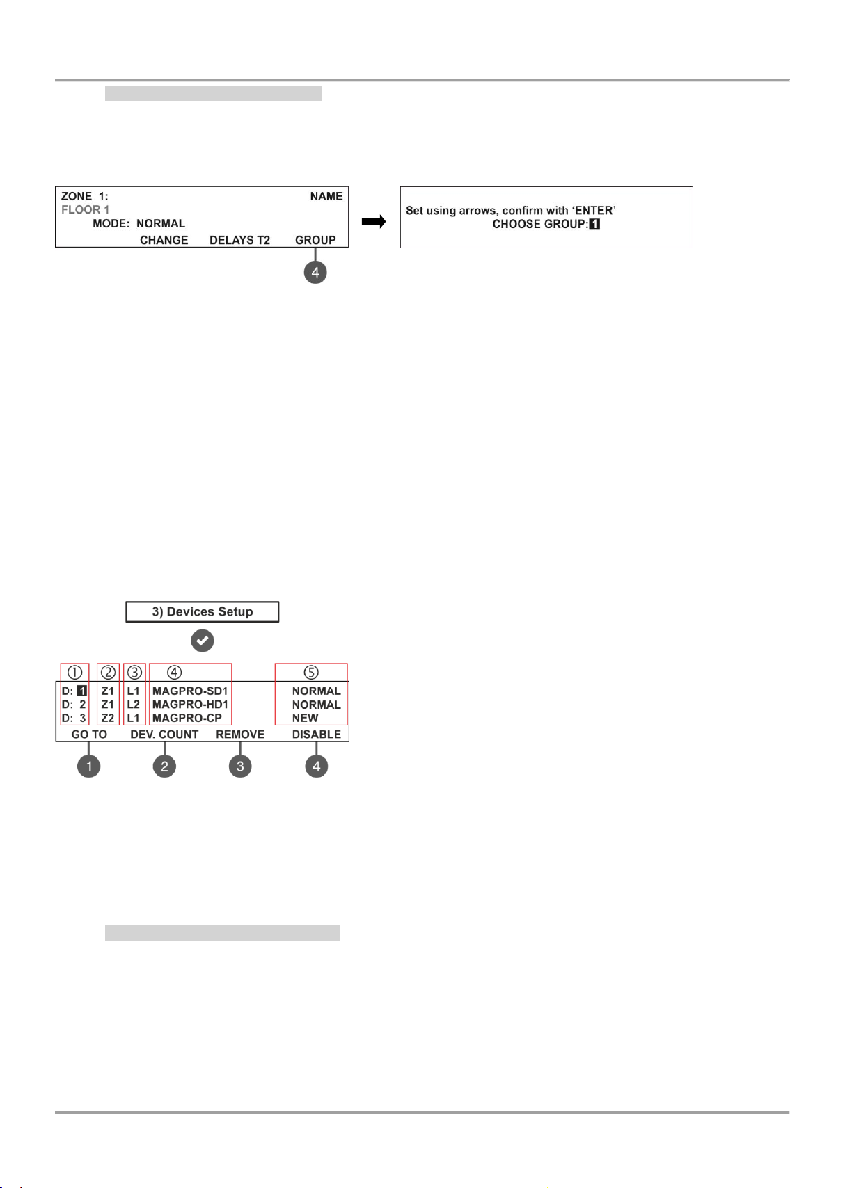
MAGPRO16 Addressable Fire Alarm Panel – Installation and Programming Manual
7.2.8 Arranging Zones in Groups
The zones in MAGPRO16 addressable fire alarm panel can be organized for operation in separate groups. The
maximum number of the permissible groups is 16. By default all zones are not associated to a group number – value 0
is set.
To enter in the submenu for group setting, press button (4) GROUP from the zone parameters programming screen.
In the field CHOOSE GROUP set the number of the group from 1 to 16. To increase the value press ‘up arrow’ button
and to decrease it – the ‘down arrow’ button. The set group number is confirmed with ENTER button.
Exit to the main screen of ZONES menu is realized with CANCEL button.
7.3. Devices Setup Menus
This menu allows the installer to review and change the status of every device. Up to 250 devices per loop are
available for settings (up to 500 when using second loop in the MAGPRO16 panel). In the ‘DEVICES SETUP’ menus
the installer can save new devices found in the system, to remove or disable them. The parameters and settings may
differ according the device type. The currently edited device address is blinking. The menu is accessible from levels 2
and 3.
From the main screen of DEVICES SETUP menu, the User can review detailed information for all connected devices in
the system configuration.
Example for the screen display after entering the menu:
The screen is divided in the following sections:
1 – Address of the device.
2 – Zone number.
3 – Loop number.
4 – System name of the device according its type.
5 – The current status of the device:
NEW – The device is new in the system. To save it press
button (3) SAVE – see item 7.3.2.
NORMAL – The device is in normal operation mode.
FAULT – The device is not responding. To delete it press (3)
REMOVE – see item 7.3.3.
WRONG TYPE – The type of the device is different from the
previously saved one.
DISABLED – The device is disabled.
FIRE – The device is in fire mode.
NONE – No device at the address.
The address number of the currently editing device is blinking. Additional submenus are available through the
functional digit buttons.
7.3.1 Submenus for General Setting
From the main screen of DEVICES SETUP menu use the functional buttons for submenus: (1) GO TO and (2) DEV.
COUNT.
Submenu (1) GO TO allows quick access to a device address in the respective loop number. The currently editable
value is blinking. Use up and down arrows to select device address. Use the left and right arrows to switch over the
editable fields. Confirm with ‘ENTER’.
Submenu (2) DEV. COUNT allows the User to check the total number of the devices connected to the system
configuration. The exit to the main screen of DEVICE SETUP menu is with pressing ENTER or CANCEL button.
31
Page 32
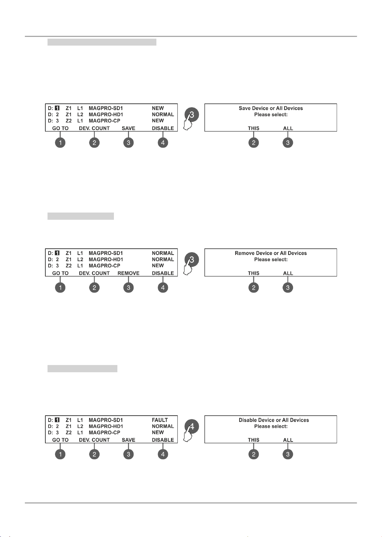
MAGPRO16 Addressable Fire Alarm Panel – Installation and Programming Manual
7.3.2 Saving the New Found Devices
The MAGPRO16-L250 loop controller automatically recognizes the types of devices in the loop. In case of finding new
devices in the system configuration (Loop 1 and Loop2) the panel displays the message “New Loop Devices Found”,
followed from information for the total number of the new devices and the loop number.
The new found devices in the system are presented with a fault type message on the main screen and a pulsed sound
signal. You can silence the buzzer with pressing the ‘SILENCE BUZZER’ button. Then enter the installation menu and
select ‘3. Devices Setup’ Menu. Press ‘ENTER’ button and follow the structure below.
To save the new found devices press the (3) SAVE button. The panel will ask if you want to save the selected device
only or all new found devices in the configuration. Choose button (2) THIS to save only the selected device and button
(3) ALL to save all new devices. The exit is automatic to the main screen DEVICE SETUP, as the saved devices are in
normal operation mode.
Note: The panel automatically saves the new devices on the serial address. The other types of addressing or changing
the current set address are described in item 7.4.
7.3.3 Deleting Devices
Every loop device can be deleted from the system configuration in the DEVICES SETUP menu. To delete one or all
devices from the system configuration, select the address of the device using up/ down arrow buttons and press button
(3) REMOVE.
The panel will ask if you want to remove the selected device only or all present devices in the configuration. Choose
button (2) THIS to remove only the selected device and button (3) ALL to remove all devices (regardless of their
current status). The exit is automatic to the main screen DEVICE SETUP.
Note: If after deleting, the removed devices are still connected physically to the system, the panel will find then and will
alert with “New Loop Devices Found” fault messages. To avoid this, it is recommended first to disconnect the device from
the system and after that to remove it from DEVICE SETUP menu.
7.3.4 Disabling Devices
From the main screen of DEVICES SETUP menu, select the device address using the up/ down arrow buttons and
press (4) DISABLE button. The panel will ask if you want to disable the selected device only or all present devices in
the configuration. Choose button (2) THIS to disable only the selected device and button (3) ALL to disable all devices
(regardless of their current status). The exit is automatic to the main screen DEVICE SETUP, as the disabled devices
are displayed with status DISABLED. The LED ‘Disable’ on the front panel is lighting on.
The panel will not follow the operation of the disabled device and will not respond to fire or fault messages from it. To
enable the device again, select its address and press the active button (4) ENABLE.
Note: If at the moment of enabling the device, it is in fire alarm mode (the fire signal was generated earlier, when the
device was still disabled) the panel will alert for the fire alarm situation immediately!
32
Page 33

MAGPRO16 Addressable Fire Alarm Panel – Installation and Programming Manual
7.3.5 Programming of Device Parameters
Attention: Programming device type parameters is available only from access level 3!
The MAGPRO16 fire alarm addressable panel operates with full range of MAGPRO addressable detectors, call points,
sounders and modules via MAGPRO communication protocol. According the type of the device, the setting parameters
are different. Use the descriptions below to set the devices in your system configuration.
To set parameters of a device go to its address number in the DEVICES SETUP menu (the editable address number is
blinking) and press ‘ENTER’.
Note: You can make the device settings also for NEW and DISABLED devices.
Association to a zone number. The first editable parameter is setting the zone number for this device. Use the up
and down arrows to set the zone number according your specific system configuration. By default all devices are
associated to Zone 1.
Entering of a specific name. The installer can enter a specific name for every device. The name can be up to 40
digits long and it is entered on the second row. Use the left and right arrows to move the cursor. The symbols (small
and capital letters and characters) are set with the up and down arrows. Confirm the entered name with ‘ENTER”. See
also the APPENDIX B.
Button (2) ON/ OFF LED – Turns on the LED of the device when checking for the presence of doubling addresses in
the loop.
Use the functional digit buttons to enter the respective submenus according the type of the selected device.
MAGPRO SD1 – Optical-smoke detector
Use the functional buttons to set the following parameters:
(1) SENSITIVITY
(2) ON/ OFF LED – Press to switch on/ off the device LED.
(3) TEST
(4) ON/ OFF LED BLINK – Alternatively changes the status of the
device LED indication.
(1) SENSITIVITY – Press the button to enter the submenu for setting
the sensitivity level of the smoke chamber for DAY and NIGHT alarm
mode.
Use the functional buttons (2) and (3) to select the sensitivity level:
Normal/ Middle/ Low/ High. All set sensitivity levels are confirmed wit
ENTER button.
(3) TEST – Press the button to enter in a new screen for checking of
the following current parameters:
- Smoke: Shows in percent the current level of smoke in the
detector’s smoke chamber
- Pollution: Shows in percent the current level of pollution in the
detector’s smoke chamber. The exit to the main screen is with pressing the CANCEL button.
MAGPRO HD1 – Heat Detector
Use the functional buttons to set the following parameters:
(1) CLASS
(2) ON/ OFF LED – Press to switch on/ off the device LED.
(3) TEST
(4) ON/ OFF LED BLINK – Alternatively changes the status of the
device LED indication.
(1) CLASS – Press the button to enter the submenu for setting the
class for DAY and NIGHT alarm mode. Use the functional buttons (2)
and (3) to select the class: A1R/ A2S/ BS. The selected class is
confirmed with ENTER button.
33
Page 34
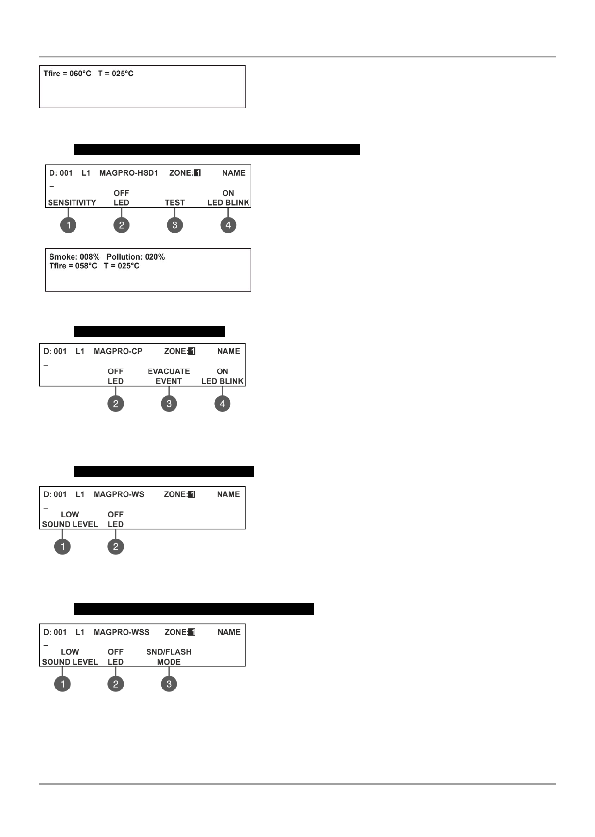
MAGPRO16 Addressable Fire Alarm Panel – Installation and Programming Manual
(3) TEST – Press the button to enter in a new screen for checking of
the following current parameters:
- T fire – Shows the operating temperature of the detector, in degrees
centigrade.
- Т – Shows the current temperature in the room, in degrees
centigrade. The selected class is confirmed with ENTER button.
MAGPRO-HSD1 – Combined optical-smoke and heat detector
Use the functional buttons to set the following parameters:
(1) SENSITIVITY – Press to set the sensitivity of the smoke
chamber for DAY and NIGHT alarm mode (see the description of
MAGPRO-SD1). The set sensitivity levels are confirmed wit ENTER
button.
(2) ON/ OFF LED – Press to switch on/ off the device LED.
(3) TEST – Press the button to enter in a new screen for checking
of the following current parameters: Smoke and Pollution (see the
description for MAGPRO-SD1) and Tfire and T (see the description
for MAGPRO-HD1).
(4) ON/ OFF LED BLINK – Alternatively changes the status of the
device LED indication.
The class for MAGPRO-HSD1 is fixed to A1R and could not be changed.
MAGPRO-CP – Manual call point
Use the functional buttons to set the following parameters:
(2) ON/ OFF LED – Press to switch on/ off the device LED.
(3) EVENT EVACUATION/ ALARM – Every pressing of the button
alternatively changes the type of the event generated with activation
of the manual call point:
- Event EVACUATION – The sounders will be activated immediately,
as the set time delays Т1 and Т2 are ignored.
- Event ALARM – The set time delays Т1 and Т2 are active and the manual call point operated as an automatic
detector.
(4) ON/ OFF LED BLINK – Alternatively changes the status of the device LED indication.
MAGPRO-WS – Wall mounted sounder
Use the functional buttons to set the following parameters:
(1) SOUND LEVEL – Every pressing of the button alternatively
changes the sound level between HIGH/ LOW – as this depends on
the number of the connected sounders to the loop:
- HIGH – Set in those cases when the number of the connected
sounders to the loop is up to 30 (sounders WS and WSS).
- LOW – Set in those cases when the number of the connected
sounders to the loop is up to 60 (sounders WS and WSS).
(2) ON/ OFF LED – Press to switch on/ off the device LED.
MAGPRO-WSS – Wall mounted sounder and strobe
Use the functional buttons to set the following parameters:
(1) SOUND LEVEL – Every pressing of the button alternatively
changes the sound level between HIGH/ LOW – as this depends on
the number of the connected sounders to the loop:
- HIGH – Set in those cases when the number of the connected
sounders to the loop is up to 30 (sounders WS and WSS).
- LOW – Set in those cases when the number of the connected
sounders to the loop is up to 60 (sounders WS and WSS).
(2) ON/ OFF LED – Press to switch on/ off the device LED.
(3) MODE – Press to choose the operation mode of the sounder:
SND – Sounder activation only;
FLASH – Flash indication only;
SND/ FLASH – Both sounder and flash indication are active;
34
Page 35

MAGPRO16 Addressable Fire Alarm Panel – Installation and Programming Manual
Sounder
Quantity
HIGH*
Sound Level
LOW**
Sound Level
Total consumption, mA
(HIGH + LOW)
WS ____ x 9,5mA
____ x 5mA
WSS ____ x 9,5mA
____ x 5mA
DBS ____ x 9,5mA
____ x 3mA
DBSS ____ x 9,5mA
____ x 3mA
Consumption of the sounders in the loop:
MAGPRO-DBS – Base with sounder
Use the functional buttons to set the following parameters:
(1) SOUND LEVEL – Every pressing of the button alternatively
changes the sound level between HIGH/ LOW – as this depends on
the number of the connected sounders to the loop:
- HIGH – Set in those cases when the number of the connected
sounders to the loop is up to 30 (sounders DBS and DBSS).
- LOW – Set in those cases when the number of the connected
sounders to the loop is up to 100 (sounders DBS and DBSS).
(2) ON/ OFF LED – Press to switch on/ off the device LED.
MAGPRO-DBSS – Base with sounder and strobe
Use the functional buttons to set the following parameters:
(1) SOUND LEVEL – Every pressing of the button alternatively
changes the sound level between HIGH/ LOW – as this depends on
the number of the connected sounders to the loop:
- HIGH – Set in those cases when the number of the connected
sounders to the loop is up to 30 (sounders DBS and DBSS).
- LOW – Set in those cases when the number of the connected sounders to the loop is up to 100 (sounders DBS
and DBSS).
(2) ON/ OFF LED – Press to switch on/ off the device LED.
(3) MODE – Press to choose the operation mode of the sounder:
SND – Sounder activation only;
FLASH – Flash indication only;
SND/ FLASH – Both sounder and flash indication are active.
Attention: It is possible to connect different type of sounders to the loop at the same time, but the total consumption of
the sounders in the loop must be up to 300mA!
Note: The automatic detectors mounted to bases DBS and DBSS are assigned at separate addresses in the control
panel!
To calculate the total consumption of the sounders in the loop and to define the proper sound level, you can use the
Table a below, as fill in the number of the used sounders according their type.
Table 1 for calculation of the total consumption of the sounders in the loop and defining the sound level:
* Note: HIGH Sound Level - Up to 30 sounders WS and WSS type; Up to 30 sounders DBS and DBSS type.
** Note: LOW Sound Level - Up to 60 sounders WS and WSS type; Up to 100 sounders DBS and DBSS type.
35
Page 36

MAGPRO16 Addressable Fire Alarm Panel – Installation and Programming Manual
Use
buttons
and
to select the generated event
The programming is same for all of the outputs.
The number of outputs are distributed into two screens. To program
OUT4 you have to press button MORE >>.
(2) ON/ OFF LED – Press to switch on/ off the device LED.
The installer has to choose an activation event using the up and
down arrows.
Use the left and right arrows to switch over the editable fields.
Other settings are available according the event type - see Table 2.
DEVICE - Activation from a device. Set the loop number and device
address. The ‘IN’ field refers only to MIO modules.
INPUT GROUP - Activation from a device in group. Set the group
number. The functional button (2) switches alternatively between
the AND and OR logic operation.
MAGPRO-Mini – Mini input module
The MAGPRO-Mini is a compact module with one input. The module monitors and transfers to control panel the state
of this input - state ON or state OFF. MAGPRO-Mini is designed for built-in installation in the mounting box of the
device.
The activation of the MAGPRO-Mini input can be programmed according the application. To program the generated
event at the input, press button (1) IN 1 – in the submenu are active two fields for setting:
GENERATES – Use the up/ down arrow buttons to select generated event at the input: FIRE/ EVACUATE/
RESET/ MESSAGE ALARM/ MESSAGE FAULT/ MESSAGE WARNING/ SILENCE BUZZER/ SILENCE
ALARM / CLASS CHANGE*
DELAY – The field is common for all events. Enter time delay 0-600 sec for activation event.
(2) ON/ OFF LED – Press to switch on/ off the device LED.
* CLASS CHANGE - To use the class change function, connect the terminals of a switch with normally open contacts
to the module terminals. The working mode of the sounders at input activation is:
- when the switch is pressed - one second sounders on, one second sounders off;
- when the switch is released - the sounder is off.
Use the left and right arrows to switch over the GENERATES and DELAY fields.
Press the functional button (2) GROUP to enter in submenu for group selection. In the editing field enter the group
number using the up/ down arrow buttons.
All set parameters are confirmed wit ENTER button. The exit to the main screen of DEVICE SETUP menu is with
pressing CANCEL button.
MAGPRO-0i4O – Module with 4 outputs
FIRE ZONE - Activation from a zone in fire alarm. Set a zone number. In the ‘ALARMS’ field you can enter a number of
registered fire alarms, when after reaching their count the output will be activated.
36
Page 37

MAGPRO16 Addressable Fire Alarm Panel – Installation and Programming Manual
FIRE ZONE GROUP - Activation from a zone in fire alarm included in a group. Set a group number.
FIRE (common) - Activation in case of fire alarm event in the system.
FAULT ZONE - Activation from a zone in fault. Set a zone number.
FAULT ZONE GROUP - Activation from a zone in fault included in a group. Set a group number.
FAULT (common) - Activation in case of fault event in the system.
FAULT SYSTEM - Activation in case of fault system event in the system.
PREALARM - Activation in case of preliminary alarm fire alarm event.
DISABLE (common) - Activation in case of disablement in the system.
SOUNDER ON - Activation in case of sounder activation in the system.
RESET - Activation in case of reset in the system.
EVACUATE - Activation in case of evacuation event in the system.
SILENCE BUZZER - Activation in case of silence buzzer in the system.
SILENCE ALARM - Activation in case of silence alarm in the system.
TEST - Activation in case of test in the system.
In addition the following fields are accessible for editing:
(2) LOGIC - Press the functional button (2) to switch over AND - OR logic for operation.
(3) DELAY - The setting is common for all activation types. Enter time delay 0-600 sec. Use the left and right arrows to
switch over the ACTIVATION and DELAY fields.
(4) BEHAVIOR CHANGE - Press the functional button (4) to set the behavior Latched or Unlatched.
The set activation event is confirmed with ENTER button. Exit to the main screen for device setup is done with
CANCEL button.
MAGPRO-2i2O – Module with 2 inputs and 2 outputs
Use the functional buttons to set parameters for inputs and outputs.
The programming is same for all of the outputs/ inputs.
For the settings of the ‘IN 1/2’ refer to the submenu of MAGPRO-Mini.
For the settings of the ‘OUT 1/2’ refer to the submenus of MAGPRO-0i4O.
(2) ON/ OFF LED – Press to switch on/ off the device LED.
MAGPRO-4i0O – Module with 4 inputs
The input numbers correspond to the functional number buttons. The programming is same for all of the inputs.
For the settings of the ‘IN 1/2/3/4’ refer to the submenu of MAGPRO-Mini.
(2) ON/ OFF LED – Press to switch on/ off the device LED.
MAGPRO-1OSi – Module potential output
The modules is used for connection of conventional sounders. Use
the functional buttons to set the following parameters:
(1) OUT 1 – Set the parameters for the output – see the description
of module MAGPRO-0i4O.
(2) ON/ OFF LED – Press to switch on/ off the device LED.
(4) ON/ OFF LED BLINK – Alternatively changes the status of the
device LED indication.
37
Page 38

MAGPRO16 Addressable Fire Alarm Panel – Installation and Programming Manual
Activation type
Parameter Settings
Loop
No
Group
No
Zone
No
Alarm
No
Device
No
Input
No*
Logic
Behavior
Device
1/2 - - - 1 - 250
1 - 4
-
Latched/ Unlatched
Input group
-
1 - 16
- - -
-
AND/OR
Latched/ Unlatched
Fire zone
- - 1 - 16
1-9 - - - Latched
Fire zone group
-
1 - 16
- - -
-
AND/OR
Latched
FIRE (common)
- - - - - - -
Latched
Fault zone
- - 1 - 16 - - - -
Latched/ Unlatched
Fault zone group
-
1 - 16
- - -
-
AND/OR
Latched/ Unlatched
FAULT (common)
- - - - - - -
Latched/ Unlatched
Fault system
- - - - - - -
Latched/ Unlatched
Pre alarm zone
- - 1 - 16 - - - -
Latched/ Unlatched
DISABLE (common)
- - - - - - -
Latched/ Unlatched
Sounder on
- - - - - - -
Latched/ Unlatched
Reset - - - - - - - Unlatched
Evacuate
- - - - - - -
Latched
Silence buzzer
- - - - - - -
Latched/ Unlatched
Silence alarm
- - - - - - -
Latched/ Unlatched
Test - - - - - - - Latched/ Unlatched
MAGPRO-R – Module for 240V interface
Relay module with interface for 240 VAC. The module is available in
two versions with 1 and 2 relay outputs. Use the functional buttons to
set the following parameters:
(1) OUT 1 – Set the parameters for the output – see the description
of module MAGPRO-0i4O.
(2) ON/ OFF LED – Press to switch on/ off the device LED.
(4) ON/ OFF LED BLINK – Alternatively changes the status of the
device LED indication.
All set parameters are confirmed wit ENTER button. The exit to the main screen of DEVICE SETUP menu is with
pressing CANCEL button.
MAGPRO-GAS – GAS Detector
MAGPRO-GAS is a gas detector designed for application in
addressable fire alarm systems with MAGPRO16/96 fire alarm
panels.
MAGPRO-GAS is designed for detection of leaking natural gas and
LPG. The detector is equipped with alarm output for management of
manipulator or electromagnetic valve (optional accessories).
Use the functional buttons to set the following parameters:
(2) ON/ OFF LED – Press to switch on/ off the device LED.
(4) ON/ OFF SOUNDER – If OFF option is set, the sounders in the system will not be activated in case of activation of
the gas detector. If ON option is set, the sounders in the system will be activated in case of activation of the gas
detector.
All set parameters are confirmed wit ENTER button. The exit to the main screen of DEVICE SETUP menu is with
pressing CANCEL button.
Table 2. Activation types – Parameters Setting:
* For input/ output module only.
38
Page 39
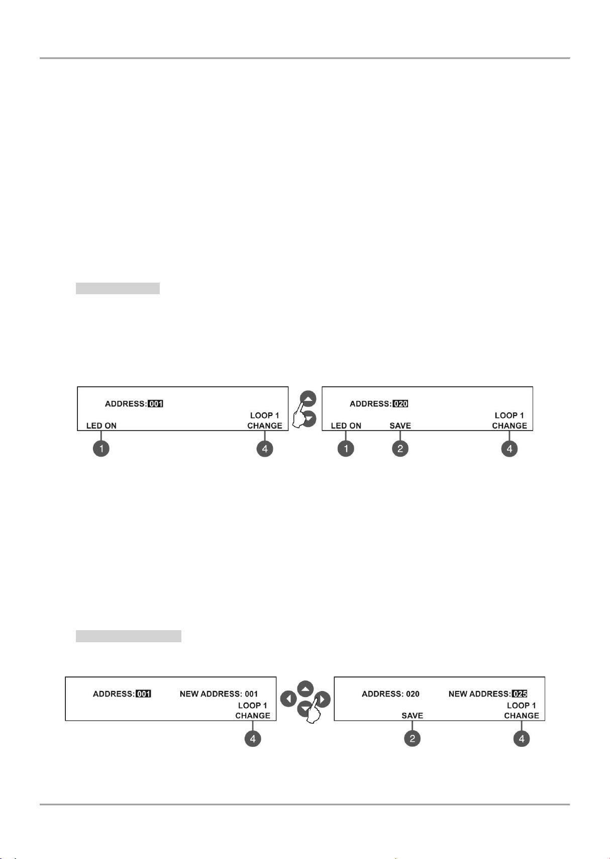
MAGPRO16 Addressable Fire Alarm Panel – Installation and Programming Manual
7.4. Addressing Menus
Attention: The addressing menus are available only from access level 3!
This menu allows the installer to set or change the device address or to perform self-addressing procedure. The type of
addressing depends on the installer’s preferences and the system capacity and configuration.
The installer can use two approaches for adding devices to the system configuration.
- The devices are directly connected to the panel Loop 1 and/ or Loop 2. The panel will recognize them and
gives automatically addresses according the order of the devices in the line. The panel will start with the first free
address in the system configuration. The installer can SAVE the new devices one-by-one or all at the time from the
Menu 3. Devices Setup.
- SELF ADDRESSING. The new devices are prepared for connection to the system configuration - the loop
line is ready but the devices are not installed (the detectors and sounders are not mounted to the bases, the call points
and modules are not connected to the loop). The installer enters 4. Addressing - 4.3. Self addressing menu. The panel
shows the first free address for every of the loops. Now the installer can start mounting detectors and modules one byone. The panel will set the displayed address number to the mounted device and automatically proceeds with next free
address in the system.
7.4.1 Set Address
In this submenu the installer can directly set addresses to new devices in the system. The procedure is same with that
for self addressing. It is suitable when the installer needs to add single devices to the system configuration at free
addresses. The detectors and sounders must not be mounted to the bases; the call points and modules must not be
connected to the loop.
To set address to a device, enter in the installer’s menu - 4. ADDRESSING - 4.1. SET ADDRESS. The device must be
prepared for connection to the panel (loop 1 or loop 2).
The system automatically shows the first address in the system. You can check the device assigned at this address
with pressing the ‘LED ON’ button - the LED(s) of the device will lighting on permanently. Next pressing of the same
button will off the LED. Use the button ‘CHANGE’ to switch to loop 2 if present in the system. The address is free if
‘SAVE’ button is active.
To find a free address use the up and down arrows to scroll over the address numbers.
The free address in the system configuration is recognized with active ‘SAVE’ functional button (2) in the last row of the
screen. Take the new device and connect it to the system - mount the detector or siren to the base or connect the
module to the loop. Press the ‘SAVE’ button and wait for a couple of seconds. If the addressing is successful the
message ‘SUCCESSFUL’ starts blinking on the screen. If the message is ‘ERROR’ then there is a problem - the device
is not properly connected; there is no communication with the panel. You can proceed with setting the next address or
escape with ‘CANCEL’ button.
7.4.2 Change Address
In this submenu the installer can change the address number of a device. To change address of a device, enter in the
installer’s menu - 4. ADDRESSING - 4.2. CHANGE ADDRESS.
The system automatically shows the first address in the system. Use the up and down arrows to select the address of
the device you want to change.
39
Page 40

MAGPRO16 Addressable Fire Alarm Panel – Installation and Programming Manual
1. During the self addressing procedure leave minimum 10 sec time interval between connecting the
next device to the loop.
2. NEVER connect devices to both loops at the same time. Connect all devices to loop 1 first and
after that proceed with loop 2.
3. After completing the self addressing procedure test the devices with LED indication on.
Use the button ‘CHANGE’ to switch to loop 2 if present in the system.
Press the right arrow button to switch to ‘NEW ADDRESS’ field.
Press right arrow button to move to field ‘NEW ADDRESS.
Use again the up and down arrows to find a free address in the system configuration - the active ‘SAVE’ functional
button (2) in the last row of the screen will appear. Press the ‘SAVE’ button and wait for a couple of seconds. If the
address changing is successful the message ‘SUCCESSFUL’ starts blinking on the screen. You can proceed with
changing other address or escape with ‘CANCEL’ button.
7.4.3 Self-Addressing
In this submenu the installer can perform self addressing procedure of devices to the system configuration. The self
addressing procedure is suitable when there are great amount of devices to be connected to the panel.
The new devices are prepared for connection to the system configuration - the loop line is ready but the devices are
not installed (the detectors and sounders are not mounted to the bases; the call points and modules are not connected
to the loop).
To perform self addressing, enter in the installer’s menu - 4. ADDRESSING - 4.3. SELF ADDRESSING. The panel
shows the first free address for every of the loops. Now the installer can start mounting detectors and modules one byone. The panel will set the displayed address number to the mounted device and automatically proceeds with next free
address in the system.
The self-addressing menu shows information about the total number
of devices connected to every loop.
On the third row the panel shows the first free address for every of
the loops. The panel skips all already set address numbers and will
jump to the next free address number.
The installer also can set manually the next address using the
functional buttons from 1 to 4. The ‘-’ will decrease the address
number and the ‘+’ will increase it. If by mistake the set address is not free, during the self-addressing procedure the
panel will skip it and will jump to the next free address number.
In self-addressing mode the panel waits for connecting the device to the loop, automatically sets the current address to
the device and moves to the next free address number. With every one added device to the system configuration the
address count will increasing to show the total number of devices connected to the respective loop.
The exit of the menu is with pressing the ‘CANCEL’ button.
IMPORTANT NOTES!
40
Page 41
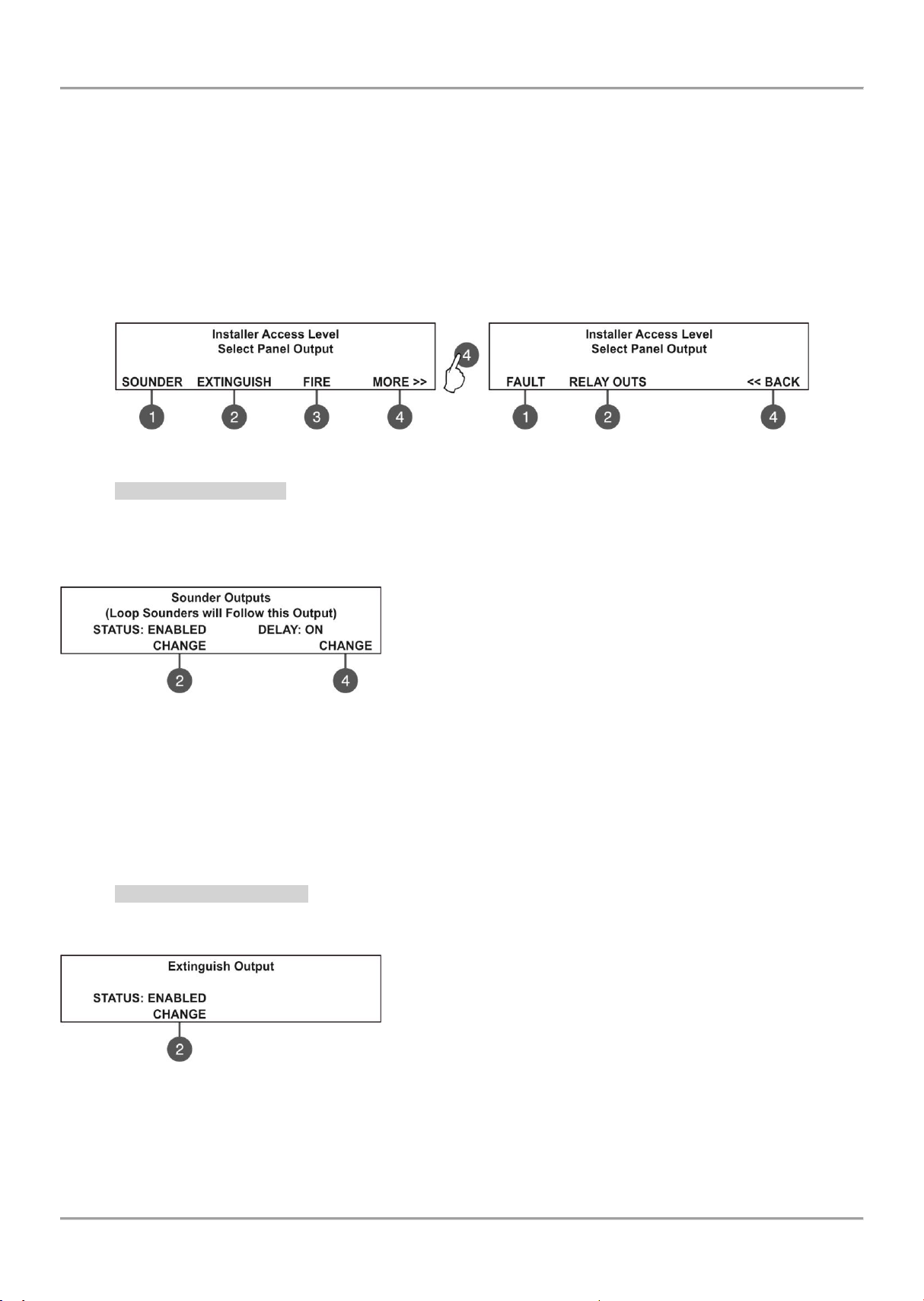
MAGPRO16 Addressable Fire Alarm Panel – Installation and Programming Manual
7.5. Panel Outputs Menus
This menu allows the installer to disable/ enable and to set time delay for some of the outputs of the control panel:
- Sounder Outputs (SND 1, SND 2)
- Extinguish Output (EXT)
- Fire Output (FIRE)
- Fault Output (FAULT)
- Four Relay Outputs
The menu is accessible from access levels 2 and 3.
To set outputs parameters, enter in the installer’s menu - 5. PANEL OUTPUTS. The submenus are allocated in two
screens.
7.5.1 Sounders Outputs
In this submenu the installer can disable/ enable the sounders activation and the time delay operation.
To access the SOUNDER submenu, enter in the installer’s menu - 5. PANEL OUTPUTS - SOUNDER (1).
Attention: In access level 2 you can only review the set delay status (ON/ OFF), with no rights to change it!
The functional buttons have the following action:
(2) - Press to change the status of the sounder outputs. Every
pressing of the button changes alternatively the ENABLED DISABLED status. When the sounder outputs are disabled the LEDs
‘Sounder Output Fault/ Disable’ and ‘Disable’ light on permanently.
(4) - Press to set the time delay operation. Every pressing of the
button changes the ‘Delay’ setting:
• ON - The delay of sounder outputs will be active when DAY operation mode is set - see the description for
menu 6.3 DAY/ NIGHT operation modes.
• OFF - No delay of sounder outputs activation. The sounder outputs are activated immediately.
• SCHEDULE - The delay of sounder outputs will be active on schedule - see the description for menu 6.3
DAY/ NIGHT operation modes.
All set parameters are confirmed wit ENTER button.
7.5.2 Extinguishing Output
In this submenu the installer can disable/ enable the extinguish output activation. To access the EXTINGUISH
submenu, enter in the installer’s menu - 5. PANEL OUTPUTS - EXTINGUISH (2).
The functional button has the following action:
(2) - Press to change the status of the extinguish output. Every
pressing of the button changes alternatively the ENABLED DISABLED status. When the extinguish output is disabled the LED
‘‘Disable’ light on permanently.
All set parameters are confirmed wit ENTER button.
41
Page 42

MAGPRO16 Addressable Fire Alarm Panel – Installation and Programming Manual
7.5.3 Fire Output
In this submenu the installer can disable/ enable the fire output activation and the time delay operation.
To access the FIRE submenu, enter in the installer’s menu - 5. PANEL OUTPUTS - FIRE (3).
Attention: In access level 2 you can only review the set delay status (ON/ OFF), with no rights to change it!
The functional buttons have the following action:
(2) - Press to change the status of the fire output. Every pressing of
the button changes alternatively the ENABLED - DISABLED status.
When the fire output is disabled the LEDs ‘Fire Output Fault/ Disable’
and ‘Disable’ light on permanently.
(4) - Press to set the time delay operation. Every pressing of the
button changes the ‘Delay’ setting:
• ON - The delay of fire output will be active when DAY operation mode is set - see the description for menu
6.3 DAY/ NIGHT operation modes.
• OFF - No delay of fire output activation. The fire output is activated immediately.
• SCHEDULE - The delay of fire output will be active on schedule - see the description for menu 6.3 DAY/
NIGHT operation modes.
All set parameters are confirmed wit ENTER button.
7.5.4 Fault Output
In this submenu the installer can disable/ enable the fault output activation.
To access the FAULT submenu, enter in the installer’s menu - 5. PANEL OUTPUTS – MORE> (4) – FAULT (1).
The functional button has the following action:
(2) - Press to change the status of the fault output. Every pressing of
the button changes alternatively the ENABLED - DISABLED status.
When the fault output is disabled the LED ‘Disable’ light on
permanently.
All set parameters are confirmed wit ENTER button.
7.5.5 Relay Outputs
Attention: The relay outputs are available for setting parameters only from access level 3!
In this submenu the installer can the set parameters of the relay outputs on the control panel PCB.
To access the RELAY OUTS submenu, enter in the installer’s menu - 5. PANEL OUTPUTS - MORE>> - RELAY OUTS
(2).
Attention! The order of the relay numbers follows that on the control panel PCB!
The programming of the relay outputs is analogical.
Use the functional buttons to set parameters for:
1 - Press to set parameters for RELAY 4
2 - Press to set parameters for RELAY 3
3 - Press to set parameters for RELAY 2
4 - Press to set parameters for RELAY 1
For the settings of the relay outputs refer to the description of the menus for MAGPRO-0i4O.
All set parameters are confirmed wit ENTER button.
The exit to the main screen of PANEL OUTPUTS is with pressing the CANCEL button.
42
Page 43
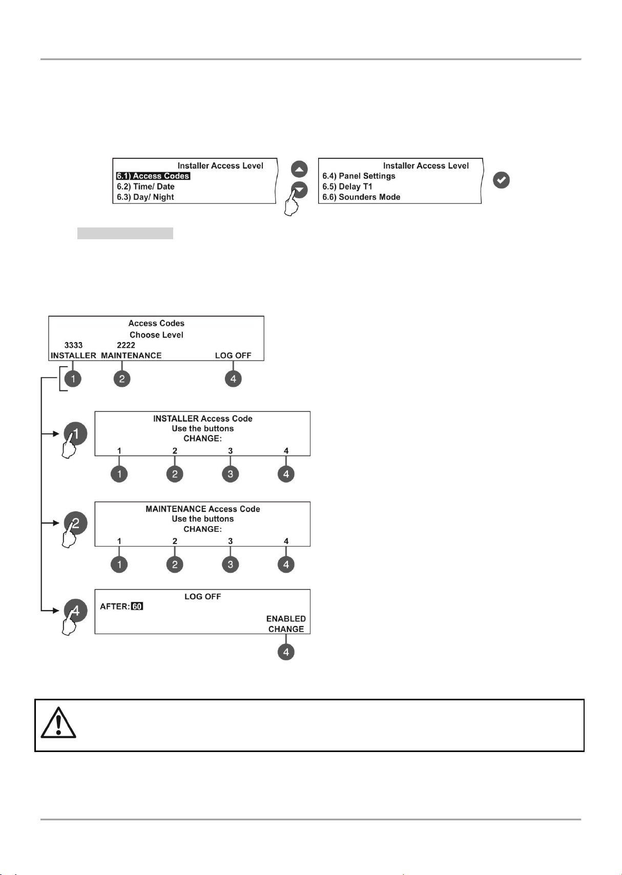
MAGPRO16 Addressable Fire Alarm Panel – Installation and Programming Manual
If the installer’s access code is changed and obscured you have to perform a hardware reset of the
panel settings!
7.6. General Settings Menu
This menu allows the installer to make some common settings for the fire panel.
The menu is accessible from access levels 2 and 3, as for the level to are introduced some restrictions.
A list with submenus is displayed after entering the installer’s menu - 6. GENERAL SETTING. The currently selected
submenu is blinking. To enter into a submenu press ‘ENTER’.
7.6.1 Access Codes
Attention: The access codes can be changed only from access level 3!
In this submenu the installer can change the code combinations for access to INSTALLER and MAINTENANCE levels.
To access the ACCESS CODES submenu, enter in the installer’s menu - 6. GENERAL SETTING - 6.1) ACCESS
CODES.
The screen displays the supported submenus and the current set access code for the INSTALLER and
MAINTENANCE programming menus:
The settings are analogical for both levels.
Use the functional buttons to set access code for:
(1) - Press to change INSTALLER CODE
(2) - Press to change MAINTENANCE CODE
(3) - Press to enter a submenu for setting time for
automatic exit from the INSTALLER and MAINTENANCE
menus.
Use the functional buttons to enter new 4-digit
INSTALLER code combination. The system will ask to
confirm the change. The exit is automatic to Access
Level main screen.
The default INSTALLER code is 3333.
Use the functional buttons to enter new 4-digit
MAINTENANCE code combination. The system will ask
to confirm the change. The exit is automatic to Access
Level main screen.
The default MAINTENANCE code is 2222.
In field „AFTER“ enter time from 0 up to 60 minutes for
automatic exit from the INSTALLER and MAINTENANCE
programming menus.
Use button (4) CHANGE to set the status:
- ENABLED – The automatic exit is enabled.
- DISABLED – The automatic exit is disabled.
43
Page 44

MAGPRO16 Addressable Fire Alarm Panel – Installation and Programming Manual
IMPORTANT NOTES!
The MAGPRO16 panel is equipped with built-in battery for saving the set time and date in case of
main or back-up power supply lost.
Put a jumper on JP7 terminals on the control panel PCB to enable the built-in battery and saving the
set time and date.
Increasing
Switching between the
editable fields
Decreasing
Set a jumper on JT7 terminal to
enable the BATT1
24VDC/ 15A
MAGPRO16
Main Board
7.6.2 Setting the Date and Time
Attention: The setting of the date and time is available only from access level 3!
In this submenu the installer can set the current time and date for the panel.
To access the TIME/ DATE submenu, enter in the installer’s menu - 6. GENERAL SETTING - 6.2) TIME/ DATE. The
screen displays:
The editable field is blinking. Use the up and down arrows to set the date and time. Use the left and right arrows to
switch over the editable fields.
7.6.3 Setting Day/ Night Alarm Modes
In this submenu the installer can set the operation alarm mode of the panel.
To access the DAY/ NIGHT submenu, enter in the installer’s menu - 6. GENERAL SETTING - 6.3) DAY/ NIGHT. The
screen displays:
Press the functional button ‘2’ to select the preferred alarm mode:
NIGHT - Select to set nighttime alarm mode. The devices will operate
only in night alarm mode.
DAY - Select to set daytime alarm level. The devices will operate
only in day alarm mode.
SCHEDULE - Select to set operation on a schedule. The devices will
operate on the programmed schedule.
The schedule is set in DAY/ NIGHT SCHEDULE submenu - press
functional button ‘4’.
In DAY/ NIGHT SCHEDULE submenu the installer can define the
day and night time intervals for all days of the week. The current
editing value is blinking.
(1) DAY CHANGE - Press to change the day of the week. Use the up
and down arrows to set the day and night time intervals for the day.
Use the left and right arrows to switch over the editable fields.
(2) ALL - Press to set the current set day and night time intervals for
all days of the week.
Confirm all settings with pressing ENTER button.
44
Page 45

MAGPRO16 Addressable Fire Alarm Panel – Installation and Programming Manual
Use the functional buttons to set:
(1) LANGUAGE - Press to set the language. Every
pressing of the button changes the currently used
language for the menus.
(2) + Brightness - Press to increase the brightness
of the screen back light. The maximum value is 20.
(3) - Brightness - Press to decrease the brightness
of the screen back light. The minimum value is 0.
(4) MORE>> - Press to switch to other panel
settings.
Confirm all settings with pressing ENTER button.
Use the functional buttons to set:
(1) Earth Fault - Press to enable/ disable the Earth Fault
indication. When the Earth Fault indication is enabled you
have to set a jumper to Earth Fault terminals on the control
panel PCB.
(2) BATTERY - Press to enable/ disable the Accumulator
Battery Fault Indication. When the Accumulator Battery
Fault Indication is enabled the panel will monitor the
internal battery resistance Ri. In normal operation Ri<0.3Ω.
If Ri>0.3Ω, the panel will alert for Battery fault with
message in Faults menu ‘Battery High Resistance’. The
installer has to change the accumulator battery with new.
(3) BUZZER – Press to enable/ disable the buzzer
signalization.
(4) << BACK - Press to switch back to previous settings.
Confirm all settings with pressing ENTER button.
7.6.4 Panel General Settings
In this submenu the installer can make some adjustments for the panel performance.
To access the PANEL SETTINGS submenu, enter in the installer’s menu - 6. GENERAL SETTING - 6.4) PANEL
SETTINGS. The screen displays:
7.6.5 Delay Т1
In this submenu the installer sets the time to Delay T1. T1 is the time delay needed for reaction of the security
personnel on the protected site. T1 provides a time delay for the personnel to go to the zone in fire alarm and to check
the situation. The operation of time delays T1 and T2 are described with the algorithm below.
To access the DELAY T1 submenu, enter in the installer’s menu - 6. GENERAL SETTING - 6.5) DELAY T1. The
screen displays:
Use the up and down arrows to set the delay T1. The time interval is
in range 0 - 60 sec.
Confirm the settings with ‘ENTER’ button.
7.6.6 Sounders Mode
In this submenu the installer sets the sounders operation mode.
To access the SOUNDERS MODE submenu, enter in the installer’s menu - 6. GENERAL SETTING - 6.6) SOUNDERS
MODE. The screen displays:
Use the functional buttons to set:
(1) – Set the alarm type sound. Enter the submenu and use the up/
down arrow buttons to select a number from 1 to 32 for the alarm
sound – the reference parameters for the selected sound are listed
on the last row of the screen.
(2) – Set the evacuation type sound. Enter the submenu and use the
evacuation sound – the reference parameters for the selected sound are listed on the last row of the screen.
(3) – The button is active only in ZONAL operation mode. The EVACUATION TIMEOUT is a time delay until
evacuation of the site. Enter the submenu and use the up/ down arrow buttons to set a DELAY time from 0 to 10
minutes. In a fire situation only the sounder of the zone(s) with alarm condition will be activated. After the set
evacuation timeout delay is over the sounders in the whole site are activated also.
(4) – Press to change the sounders operation mode.
• Common - All sounders will be activated with no sense of zone to which they are connected.
• Zonal - Only the sounder of the zones with alarm condition will be activated.
Confirm the settings with ‘ENTER’ button.
up/ down arrow buttons to select a number from 1 to 32 for the
45
Page 46

MAGPRO16 Addressable Fire Alarm Panel – Installation and Programming Manual
7.7. Save Configuration Menu
Attention: Saving the system configuration is available only from access level 3!
In this menu the installer performs saving of the new found devices in the system configuration. The panel will ask for
confirmation of the action. The screen displays.
Use the functional buttons to confirm or reject the save configuration.
You can also escape from this menu with ‘CANCEL’ button.
7.8. Restore Defaults Menu
Attention: The restore defaults menu is available only from access level 3!
In this menu the installer performs reset to default settings of the system configuration. The panel will ask for
confirmation of the action. The screen displays.
Use the functional buttons to confirm or reject the restore defaults
settings. You can also escape from this menu with ‘CANCEL’ button.
7.9. Software Revision
In this menu the installer can review the software versions of the main board and used loop modules and also has
possibility for firmware update of the main processor unit. The screen displays:
Use the functional button ‘4’ to perform firmware UPDATE of the
main processor – the steps for firmware update are described in
details in item 3.3.
You can also escape from this menu with ‘CANCEL’ button.
46
Page 47

MAGPRO16 Addressable Fire Alarm Panel – Installation and Programming Manual
For future use
7.10. Network
In this menu the installer can make the settings for the redundant network between fire panels.
7.10.1 Network Settings
To access the NETWORK settings, enter in the installer’s menu - 10. NETWORK – 10.1) SETTINGS. The screen
displays:
In this submenu the installer enters a number, name and sets the status of the panel in the redundant network. Use the
up/ down arrow buttons to set the panel number. Move on the second row with right arrow button and enter a specific
name up to 40 symbols, including intervals. Use the button (4) – CHANGE to set the status of the panel in the
redundant network - ENABLED (the panel is enabled for operation in the network) / DISABLED (the panel is disabled
for operation in the network). When the panel is DISABLED from the network it will not receive messages from other
panels and will be visualized as FAULT.
Confirm the setting with ‘ENTER’ button. You can also escape from this menu with ‘CANCEL’ button.
7.10.2 Panels Settings
To access the PANELS settings, enter in the installer’s menu - 10. NETWORK – 10.2) PANELS.
On the screen are listed the panels with their current state in the
redundant network:
NEW – The panel is new in the system. To save it press
button (3) SAVE.
NORMAL – The redundant network is enabled.
THIS – The panel from which the redundant network is
reviewed.
FAULT – The panel is DISABLED or there is problem with the redundant network.
NONE – No panel connected to the redundant network.
All new panels connected to the redundant network can be saved with (3) SAVE button. The panels with current state
NORMAL, THIS and FAULT can be deleted from the network with (3) REMOVE button.
If a new panel enabled in the network is with number already set for another panel the “GENERAL FAULT” LED will
lights on and a message for fault event “Double Panel number” is generated. The installer should change the doubled
panel number for proper operation in the redundant network.
For every panel the installer can set individually the panel’s activity to Receive/ Send messages and/ or commands.
The settings for sending commands can be done only for THIS panel (current panel).
Use the (3) CHANGE button to set the options:
NONE – The panel cannot send any commands to other
panels in the redundant network.
COMMANDS – The panel can send commands to other
panels in the redundant network.
The settings for receiving commands can be done for all other panels.
Use the (1) CHANGE button to set the options:
NONE – The panel will not receive any data from the other
panels in the redundant network.
MESSAGES - The panel will receive only messages from
other panels in the redundant network.
COMMANDS – The panel will receive only commands from
other panels in the redundant network.
MESSAGES & COMMANDS - The panel will receive commands and messages from other panels in the
redundant network.
47
Page 48
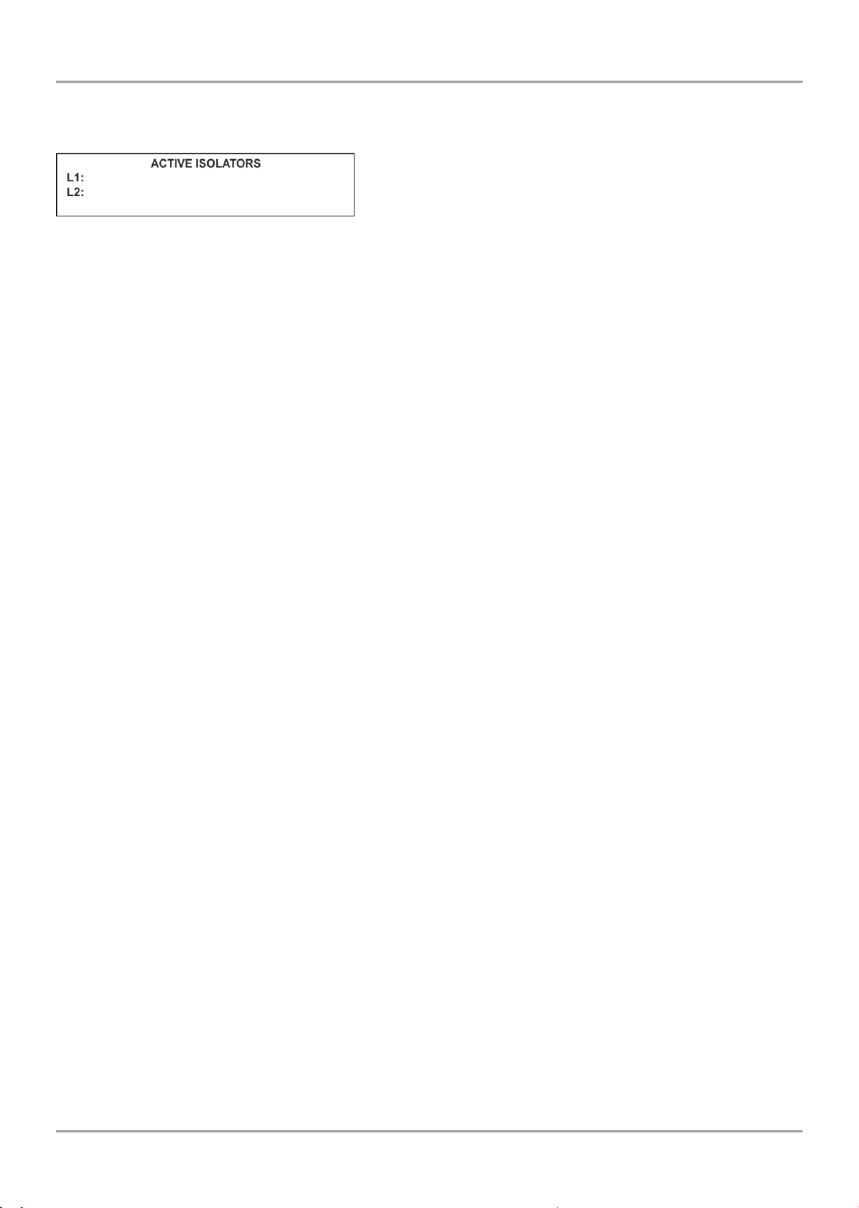
MAGPRO16 Addressable Fire Alarm Panel – Installation and Programming Manual
7.11. Active Isolators Menu
This is an information menu for reviewing the active isolators (built-in isolator in MAGPRO devices).
The active isolators in the system are displayed as device addresses in the fields “L1” and “L2” for MAGPRO loops.
7.12. Access Level 1
Exit from Access Levels 2 and 3 to Access Level 1.
After choosing the menu with button ENTER the panel automatically returns to Access Level 1. To enter in Access
Level 2 (Maintenance) and Access Level 3 (Installer) again the user has to enter a valid code for the respective access
level.
48
Page 49

APPENDIX А
Message
Description
Flash Error
FLASH Memory error is detected.
Ram Error
RAM Memory error is detected.
New Periphery Devices Found
New periphery devices are found in the system configuration.
Periphery Device Fault
The device is not responding (the device is lost or failed).
Periphery Device Type Error
A periphery device with different type is found on the address.
AC Loss
The charging device is failed.
Battery Low
The accumulator battery is discharged.
Battery Loss
The accumulator battery is missing.
Battery High Resistance
High value (Ri>0.3Ω) of the battery internal resistance. Replace the battery immediately!
Earth Fault
Resistive connection between some signals and earth < 10k.
Charger Fault
The charging unit is failed.
Sounder1 Short
Short circuit detected at Sounder 1 output.
Sounder2 Short
Short circuit detected at Sounder 2 output.
Sounder1 Open
Circuit broken at Sounder 1 output.
Sounder2 Open
Circuit broken at Sounder 2 output.
Fire Output Short
Short circuit detected at Fire output.
Fire Output Open
Circuit broken at Fire output.
EXT Output Short
Short circuit detected at Extinguishing output.
EXT Output Open
Circuit broken at Extinguishing output.
Fault Output Short
Short circuit detected at Fault output.
Fault Output Open
Circuit broken at Fault output.
Fault Power AUX
Short circuit (the mains power supply is lost).
Alarm Confirm Input Short
Short circuit detected at input ‘Alarm Confirmation’.
Alarm Confirm Input Open
Circuit broken at input ‘Alarm Confirmation’.
Alarm Confirm Input On
‘Alarm Confirmation’ input activation.
Protection Alarm Confirm Short
Short circuit detected at input ‘Protection Alarm Confirmation’.
Protection Alarm Confirm Open
Circuit broken at input ‘Protection Alarm Confirmation’.
Protection Alarm Confirm On
‘Protection Alarm Confirmation’ input activation.
Fault Protection Panel Input Short
Short circuit detected at input ‘Protection Panel Fault’.
Fault Protection Panel Input Open
Circuit broken at input ‘Protection Panel Fault’.
Fault Protection Panel Input On
‘Protection Panel Fault’ input activation.
Protection Panel Fault
The extinguishing panel failure.
Loop Break
The loop is broken.
Loop Short
Short circuit detected in the loop.
New Loop Devices Found
New loop devices are found in system configuration.
Loop Zero Address
There is a device without address number (a device with addres 0 is applied).
Double Panel number
Doubling of the panel number (when two or more panels are connected in a network).
Panel Fault
Fault in the connection with another panel (when two or more panels are connected
in a network).
Reset
Reseting of the panel.
Silence Alarm
The sounders have been silenced.
Zone Disabled
The zone is disabled.
Table: Event Messages.
MAGPRO16 Addressable Fire Alarm Panel – Installation and Programming Manual
49
Page 50

MAGPRO16 Addressable Fire Alarm Panel – Installation and Programming Manual
Earth Fault function DISABLED
The Earth Fault indication is disabled.
Sounder Disabled
The Sounders are disabled.
Fire Brigade Output Disabled
The fire output is disabled.
Fire Protection Output Disabled
The extinguishing output is disabled.
Fault Output Disabled
The fault output is disabled.
Zone In Test
The zone is in test mode.
Transmitting device active
The Fire output is activated.
Extinguishing output active
The Extinguishing output is activated.
Sirens active
The sounders are activated.
User log off
Maintenance level exit.
Installer log off
Installer level exit.
User log on
Maintenance level entry.
Installer log on
Installer level entry.
High Resistance Disabled
The indication for high battery resistance is disabled.
Total loss of Power
The mains powers supply is lost.
Buzzer Disabled
The internal buzzer is disabled.
Network Break
Redundant network breakdown.
Loop Device Disabled
The loop device is disabled.
Chamber Fault
Fault in the detector.
Clean Me Now
Dirty detector chamber.
Loop Device Input Fault
Fault in loop device input.
Loop Device Output Fault
Fault in loop device output.
Alarm
Fire signal from detector.
PreAlarm
Fire signal from detector in 2DEVICES or DOUBLE operation mode for zone.
Test Fire
Fire signal from tested detector.
Loop Device Type Error
A different than the expected type of device has been detected at the address.
Loop Device Fault
The device does not respond (lost or damaged).
Double Address
More than one device with the same address in the loop.
Evacuate
Activated Call Point or EVACUATE button on the panel.
Log Fault
The Log file event is lost or damaged.
[
! ” # $ % & ‘ ( ) * + , - . / 0 1 2 3 4 5
6 7 8 9 : ; < = > ? @ A B C D E F G H I J
K
L M N O P Q R S T U V W X Y Z [ ] ^ _ ` a b c d e f g h i j k l m n o p q r s t u v w x y z
APPENDIX B
Table: Text and symbols for introducing device and zone names.
In device or zone name entering mode, every pressing of up/ down arrow button changes the entered letter or symbol.
When moving to the next new position the entering starts from the begging of the table.
50
Page 51

APPENDIX C
Initial power up of the system.
MAGPRO16 Addressable Fire Alarm Panel – Installation and Programming Manual
51
Page 52

MAGPRO16 Addressable Fire Alarm Panel – Installation and Programming Manual
APPENDIX D
Two steps of alarming Algorithm.
52
Page 53

MAGPRO16 Addressable Fire Alarm Panel – Installation and Programming Manual
APPENDIX E
Tree structure of the programming menus.
The presented tree structure describes the full access to the programming menus from level 3 – Installer. From access
level 2 – Maintenance, some of the programming menus are not displayed or the operation with them is partially limited
– see also the Table on page 21.
53
Page 54

MAGPRO16 Addressable Fire Alarm Panel – Installation and Programming Manual
Tree structure of the menus – continue.
54
Page 55

18020181, Rev B , 12/ 2014
Elite Security Products Ltd, Unit 7 Target Park,
Shawbank Road, Lakeside, Redditch B98 8YN, UK
Tel.: 01527 515150
http://www.espuk.com
 Loading...