

ESP MAG816 Installation And Operation Manual
FIRE CONTROL PANEL
MAG816
INSTALLATION AND OPERATION
MANUAL
READ THIS MANUAL BEFORE CONNECTING THE
EQUIPMENT AND KEEP IT SAFE FOR FUTURE REFERENCE.
To call our technical support line dial:
+44 (0) 1527 51 51 50

2 MAG816 - Installation and Operation Manual
Contents
Installer Instruction
GUARANTEE ...............................................................................................................3
1. GENERAL INFORMATION ......................................................................................4
2. TECHNICAL SPECIFICATIONS ..............................................................................4
2.1 General Technical Specications of MAG816 ...........................................4
2.2 General Technical Specications of Relay Module MR8 ...........................5
3. INSTALLING MAG816 .............................................................................................6
3.1 Wall Mounting .............................................................................................7
3.2 Flush Mounting ...........................................................................................7
3.3 Conguration of the Basic Modules ............................................................8
3.4 Control Module ...........................................................................................9
3.5 Main Power Source ....................................................................................10
Connecting of the Main Power Source .........................................................10
Connecting to the Battery .............................................................................10
3.6 4-Zone Expander ........................................................................................11
Connecting of Additional 4-Zone Expander ..................................................11
3.7 4-Sounder Expander ..................................................................................12
Performance and Connecting of 4-Sounder Expander.................................12
4. CONNECTING
4.1 Relay Module MR8 .....................................................................................13
4.2 Repeater Panel...........................................................................................15
4.3 Class Change Mode ...................................................................................16
4.4 Connecting the Zone and Sounder Circuits................................................16
5. SYSTEM PROGRAMMING
5.1 Sounder Delay ............................................................................................18
5.2 Double Action Mode ...................................................................................19
5.3 Instant Action Mode ....................................................................................19
5.4 Master Panel Mode ....................................................................................20
5.5 Repeater Panel Mode.................................................................................20
5.6 Single Panel Mode .....................................................................................20
6. OPERATION INSTRUCTIONS
6.1 Initial Start-up of MAG816 ..........................................................................21
6.2 Front Panel .................................................................................................21
6.3 Buttons .......................................................................................................22
6.4 LED Indication ............................................................................................22
6.5 Sound Signal ..............................................................................................23
6.6 Service Modes ............................................................................................23
7. INDICATION
7.1 Faults Indication .........................................................................................26
7.2 Indication of the Operation Modes..............................................................27
GENERAL CONNECTION CIRCUIT OF MAG816 ......................................................28
FIRE ALARM RECORD ...............................................................................................29
SERVICE RECORD .....................................................................................................30
FIRE ALARM EVENT LOG ..........................................................................................30
SPARE PARTS KITS ...................................................................................................31

MAG816 - Installation and Operation Manual 3
GUARANTEE
During the guarantee period the manufacturer shall, at its sole discretion, replace or repair any defective product
when it is returned to the factory. All parts replaced and/or repaired shall be covered for the remainder of the
original guarantee, or for ninety (90) days, whichever period is longer. The original purchaser shall immediately
send manufacturer a written notice of the defective parts or workmanship, which written notice must in all cases
be received prior to expiry of the guarantee.
INTERNATIONAL GUARANTEE
Foreign customers shall enjoy the same guarantee rights as those enjoyed by any customer in Bulgaria, except
that manufacturer shall not be liable for any related customs duties, taxes or VAT, which may be payable.
GUARANTEE PROCEDURE
This guarantee will be granted when the appliance in question is returned. The manufacturer shall accept no
product whatsoever, of which no prior notice has been received.
CONDITIONS FOR WAIVING THE GUARANTEE
This guarantee shall apply to defects in products resulting only from improper materials or workmanship, related
to its normal use. It shall not cover:
• Damages resulting from improper transportation and handling;
• Damages caused by natural calamities, such as re, oods, storms, earthquakes or lightning;
• Damages caused by incorrect voltage, accidental breakage or water; beyond the control of the manufacturer;
• Damages caused by unauthorized system incorporation, changes, modications or surrounding objects;
• Damages caused by peripheral appliances unless such peripheral appliances have been supplied by the
manufacturer;
• Defects caused by inappropriate surrounding of installed products;
• Damages caused by failure to use the product for its normal purpose;
• Damages caused by improper maintenance;
• Damages resulting from any other cause, bad maintenance or product misuse.
In the case of a reasonable number of unsuccessful attempts to repair the product, covered by this guarantee, the
manufacturer’s liability shall be limited to the replacement of the product as the sole compensation for breach of the
guarantee. Under no circumstances shall the manufacturer be liable for any special, accidental or consequential
damages, on the grounds of breach of guarantee, breach of agreement, negligence, or any other legal notion.
WAIVER
This Guarantee shall contain the entire guarantee and shall be prevailing over any and all other guarantees,
explicit or implicit (including any implicit guarantees on behalf of the dealer, or adaptability to specic purposes),
and over any other responsibilities or liabilities on behalf of the manufacturer. The manufacturer does neither
agree, nor empower, any person, acting on his own behalf, to modify or alter this Guarantee, nor to replace it with
another guarantee, or another liability with regard to this product.
UNWARRANTED SERVICES
The manufacturer shall repair or replace unwarranted products, which have been returned to its factory, at its sole
discretion under the conditions below. The manufacturer shall accept no products for which no prior notice has
been received.
The products, which the manufacturer deems repairable, will be repaired and returned. The manufacturer has
prepared a price list and those products, which can be repaired, shall be paid for every repaired appliance.
The closest equivalent product, available at the time, shall replace the products manufacturer deems un-repairable.
The current market price shall be charged for every replaced product.
ATTENTION
This manual contains an information about the limitations in using and operation of the product, as and
information about the limits in the responsibility of the manufacturer. Please read the operation manual
carefully before starting the installation.

4 MAG816 - Installation and Operation Manual
1. GENERAL INFORMATION
The MAG816 is a conventional microprocessor fire control panel, designed according
to EN54 Standard requirements. The panel provides for monitoring and reporting
fire events in up to 16 separate zones, depending on the installed configuration.
The MAG816 must be installed according to the Fire Alarm Installation Regulations,
mandatory for the territory of the respective country. The electrical power supply to
the panel must be isolated and must not be capable of being accidentally switched
off. The power switch-off board should display a clear FIRE ALARM - DO NOT
SWITCH OFF label.
2. TECHNICAL SPECIFICATIONS
2.1 General Technical Specications of MAG816
▪ Maximum number of detectors per zone: - Up to 32 conventional detectors with
consumption < 200µА at a normal mode;
- Unlimited number of manual call points.
▪ Thresholds for zone conditions:
• 0 ÷ 2 mA - Open circuit fault condition.
• 2 ÷ 10 mA - Normal condition.
• 10 ÷110 mA - Fire alarm condition.
• > 110 mA - Short circuit condition.
▪ Power Supply:
• Main Power Supply ~ 230V AC ±10%
2А Fuse, T -Type.
• Stand-by Power Supply 1 Accumulator battery 12V/ 18Ah
Dimensions - 167х181х76mm
Voltage Output - U
CHARGE
= 13,8V
Current Output - I
MAX
= 2A
7А Fuse, Resettable (PTC)
Battery connection: with a at terminal
lug Ø5mm
▪ Consumption from 230V in normal
working mode and a fully charged
battery:
• At 4 zones (1 Zone Expander) 2,1VA
• At 16 zones (4 Zone Expanders) 4,2VA
▪ Consumption from the battery at mains
power supply failure in normal working
mode:
• With connected 1 Zone Expander 130mA
• With connected 4 Zone Expanders 260mA
▪ Consumption from the battery in Fire alarm
condition:
• At 1 Zone Expander, Fire in 1 zone 330mA
• At 1 Zone Expander, Fire in 4 zones 720mA
▪ Outputs:
• Sounder circuits SND1÷SND4 +24V/ 0.3A
(control module) Resettable (PTC) Fuse
MAG816 - Installation and Operation Manual 5
• Sounder circuits SND1÷SND4 +24V/ 0.15A
(4-Sounder Expander) Fuse, Resettable (PTC)
• Fault Relay, volt free changeover contacts* +12V/ 1A or 24V/ 0.5A
U
MAX
= 125V; I
MAX
= 2A
• Fire Relay, volt free changeover contacts* +12V/ 1A or 24V/ 0.5A
U
MAX
= 125V; I
MAX
= 2A
* Note: These functions may not be used to
provide any “Options with requirements” as
specied in EN54-2.
• Auxiliary output +24V DC/ 0,3А
Fuse, Resettable (PTC)
▪ Cabling of the main power supply:
• Recommended wires cross section 1.5mm
2
• Terminal maximum wire diameter Ø2.5mm
▪ Environment:
• Working temperature -5 ÷ +40ºС
• Storage temperature -20 ÷ +60ºС
• Humidity Up to 93% (non condensing)
2.2 General Technical Specications of Relay Module MR8
▪ Number of relays: 8
▪ Power supply: 24V
▪ Current consumption in normal condition: 8mA
▪ Additional current consumption for every
relay switched ON: 10mA
▪ Maximum ratings of volt-free changeover
contacts: 12V/ 1A or 24V/ 0.5A
▪ Maximum voltage: 125V
▪ Maximum consumption: 2A
▪ Cabling:
• Recommended wires cross section 1.5mm
2
• Terminal maximum wire diameter Ø2.5mm
▪ Environment:
• Working temperature -5 ÷ +40ºС
• Storage temperature -20 ÷ +60ºС
• Humidity Up to 93% (non condensing)
WARNINGS:
Prior to connecting the MAG816 Fire Alarm Panel, perform a thorough
test of the all wiring integrity of the entire system.
Should a fault arise during installation and connection, which cannot
be removed, stop the installation and call the producer or his regional
authorized representative!
TECHNICAL SUPPORT HELP
TEL.: +44 (0) 1527 51 51 50
!

6 MAG816 - Installation and Operation Manual
3. INSTALLING MAG816
• Select the best location for the panel away from sources of heat, environmental dust
and potential water ingress, with an ambient temperature of between -5°C and + 40°C,
Figure 1.
• Undo the two secure bolts - Figure 2. Use the instrument supplied for the purpose in
the set (hexagonal tool No. 2).
• Open the front panel and disconnect the earth cables: from the 230 V clamps, from the
metal bottom clamps and from the chassis.
• Disconnect the indication ribbon cable.
• Remove the front panel by undoing the screws of the hinges - Figure 3. (NB. The
screws at the metal bottom can also be undone. What is special here is that there are
two plastic pads under the every hinge. These pads need to be placed back again under
the hinges when mounting the front panel.)
• Select the input openings for the cables and place a plastic cap, provided with the panel
accessories, on those which are not going to be used, see Position 9 from the spare
parts kit on page 31.
• Perform an exposed or ushed mounting (option) - see items 3.1 and 3.2.
• Run all external cables into the box to establish connection but do not connect them
at this stage yet. Run the mains cable through the chosen opening but keep it
away from the low voltage wirings.
• Connect the mains supply and earth to the main terminal block but do not switch the
main electrical supply on at this stage.
• Place the plastic lightpipe (see Positions 7, 11 and 15, page 31), provided with the
spare parts kit, at their designated locations on the main module, zone and/or sounder
expanders.
• Position the battery and secure it with the clamp - Figure 9, Position 1.
• Connect the zone and sounder circuits and program the panel according to the specic
application.
• Mount the front panel back onto the hinges and connect the indication ribbon cable and
the earth cables: to the 230 V clamps, to the metal bottom clamps and to the chassis.
• After all system programming and testing operation are complete, screw both secure
bolts with the help of the hexagonal tool supplied.
Figure 1. Figure 2. Figure 3.
MAG816 - Installation and Operation Manual 7
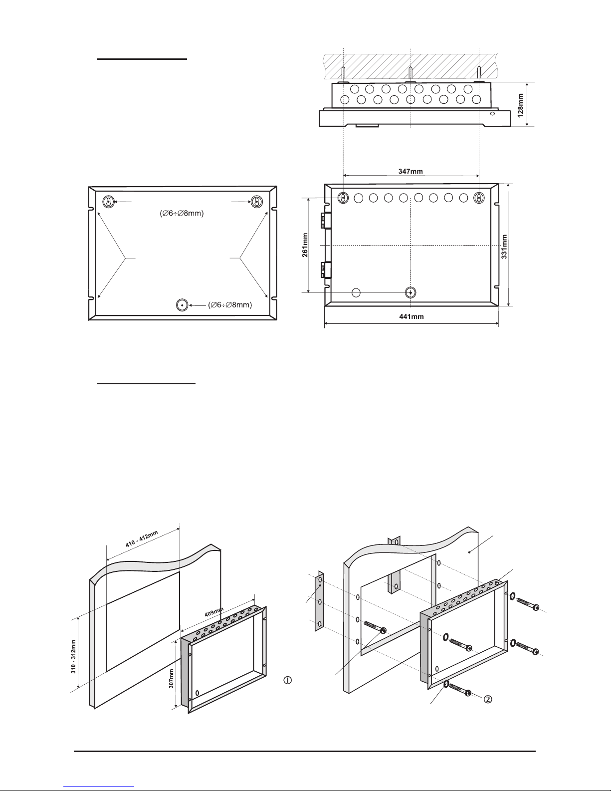
3.1 Wall Mounting
• Use the template supplied to determine
the openings of the metal bottom onto the
wall - Figure 4.
• Drill Ø6-8mm diameter openings in the
wall and x the box using the provided
anchors and screws (Positions 2 and 4,
page 31) - Figure 5.
Figure 4. Figure 5.
3.2 Flush Mounting (option)
The accessory set provided contains two special hangers for ushed wall mounting
(position 20, page 31) of the re alarm panel on 25 mm thick drywall.
• Use the dimension shown in Figure 6 to draw and cut out the mounting openings in
the drywall.
• Attach the hangers to the internal side of the wall and x them with the screws (Position
19, page 31), as shown in Figure 7, Position 1.
• Run all external cables in the box and then place it into the mounting opening. Fix the
bottom using the mounting screws and washers (Positions 17 and 18, page 31) - Figure
7, Position 2.
Figure 6. Figure 7.
WASHER
METAL BOX
25mm THICK
DRYWALL
SCREWS FOR
FLUSH MOUNTING
SCREWS FOR
HANGER FIXING
HANGER
TEMPLATE
DRILL HERE
FLUSH MOUNTING
8 MAG816 - Installation and Operation Manual
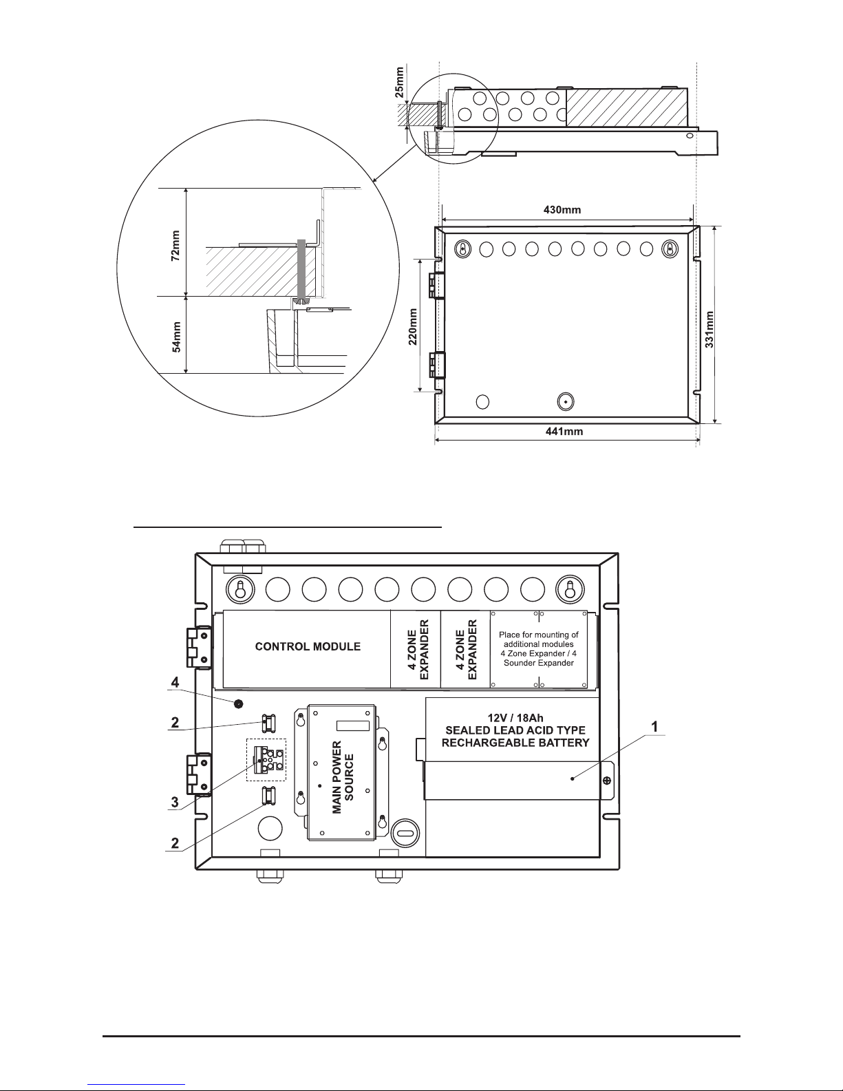
Figure 8. Flush mounting holes.
Main view of the xed to the wall hangers and the bolts supporting the metal box.
3.3 Conguration of the Basic Modules
Figure 9.
• 1 - Metal clamp for supporting the battery.
• 2 - Clamp for supporting the main power supply cable.
• 3 - Terminal for connecting between the mains power supply and the power
source. T-type fuse 2A (Position 3, page 31).
• 4 - Earthing point.
MAG816 - Installation and Operation Manual 9
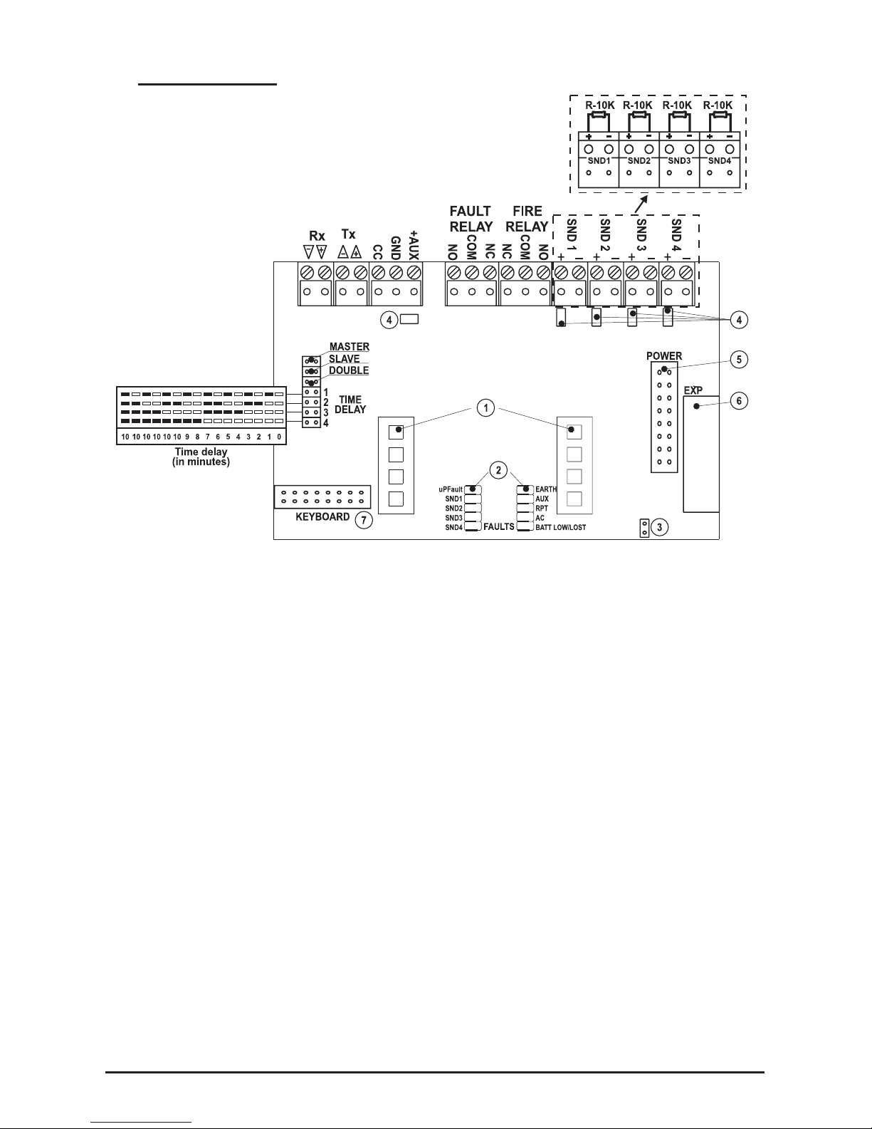
3.4 Control Module
Figure 10.
• Rx/Tx - Terminals for connecting of Repeater, Relay Module or a combined connection
between them (see items 4.1 and 4.2);
• CC (Class change) - Terminal for connecting of a switch (see item 4.3);
• GND - Grounding;
• +AUX - Auxiliary output, +24V DC / 0,3A;
• FAULT RELAY - Fault Relay, +12V / 1A or +24V / 0,5A;
• FIRE RELAY - Fire Relay, +12V / 1A or +24V / 0,5A;
• SND 1 ÷ SND 4 - Sounder outputs, +24V / 0,3A; Mount the resistors R-10K from the
supplied spare parts kit (position 1, page 31) to the sounder terminals;
• DOUBLE - Double Action Mode (see item 5.2);
• MASTER - Master Panel Mode (see item 5.4);
• SLAVE - Repeater Panel Mode (see item 5.5);
• TIME DELAY - Sounder Delay Programming.
- LED Indication of the operation modes, lightpipe mounted (Position 7, page 31);
- Faults LED indication, see item 7.1;
- Jumper for enable/disable Earth Fault Indication;
- Resettable (PTC) fuses;
- Connector for connecting the main power source;
- Connector for connecting 4-zone / 4-sounder expander;
- Connector for connecting the control panel keypad.
Table for Sounder
Delay Programming
(in minutes).
MAG816
10 MAG816 - Installation and Operation Manual
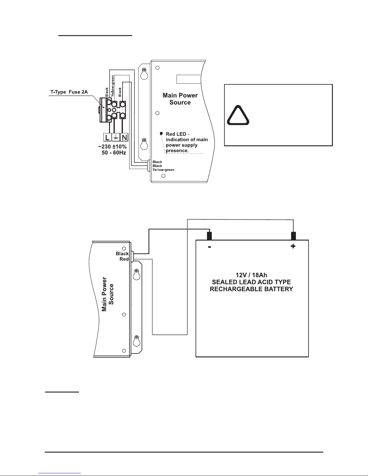
3.5 Main Power Source
Connecting of the Main Power Source
Figure 11.
Connecting to the Battery
Figure 12.
Attention: It is possible that the battery might not be charged at the panel initial start-up.
In this case the BATT LOW/LOST at the control module and the GENERAL FAULT at
the front panel will light on until the battery will be charged up to the required level.
The yellow-green
earthing cable of the
main power source
must be connected
to the middle point of
the terminal!
!
 Loading...