

Page 1
C C T V M o n i tor with int e g ra t e d DV R
INTEGRA 4 / INTEGRA 8
USER MANUAL FOR
Page 2

CAUTION
RISK OF ELECTRIC SHOCK, PLease DO NOT REMOVE COVER WHEN
POWER CONNECTED. NO USER SERVICEABLE PARTS INSIDE.
REFER SERVICING TO QUALIFIED SERVICE PERSONNEL.
WARNING
TO PREVENT FIRE OR ELECTRIC SHOCK HAZARD, DO NOT EXPOSE
THIS APPLIANCE TO RAIN OR MOISTURE.
NOTE: This equipment has been tested and found to comply with
the limits for a Class “A” digital device, pursuant to Part 15 of the
FCC Rules. The
protection against harmful interference when the equipment is
operated in a commercial environment. This equipment generates,
uses, and can radiate radio frequency energy and, if not installed
and used in accordance with the instruction manual, may cause
harmful interference to radio communications.
imits are designed to provide reasonable
se l
FCC Caution: To assure continued compliance, use only shiel
rface cables when connecting to computer or peripheral devices.
inte
ded
Any changes or modifications not expressly approved by the party
responsible for compliance could void the user’s authority to operate
this equipment.
This Class A digital apparatus meets all the requirements of the FCC
Regulations.
Copyright Statement
All rights reserved. No part of this publication may be reproduced in any form or by any
eans, transcribed, translated into any language or computer language, transformed in
m
any other way, stored in a retrieval system, or transmitted in any form or by any means,
electronic, mechanical, recording, photocopying or otherwise, without the prior written
permission of the owner.
2
Page 3
Contents
Safety Instructions . . . . . . . . . . . . . . . . . . . . . . . . . . . . . . . . . . . . . . . . . . . . . . . . . . . . . . . 4
Controls . . . . . . . . . . . . . . . . . . . . . . . . . . . . . . . . . . . . . . . . . . . . . . . . . . . . . . . . . . . . . . . . . 5
Getting Started and the Main Screen . . . . . . . . . . . . . . . . . . . . . . . . . . . . . . . . . . . . . . . 9
Recording . . . . . . . . . . . . . . . . . . . . . . . . . . . . . . . . . . . . . . . . . . . . . . . . . . . . . . . . . . . . . . 12
Playback . . . . . . . . . . . . . . . . . . . . . . . . . . . . . . . . . . . . . . . . . . . . . . . . . . . . . . . . . . . . . . . 13
Video Backup . . . . . . . . . . . . . . . . . . . . . . . . . . . . . . . . . . . . . . . . . . . . . . . . . . . . . . . . . . 14
Remote Viewing . . . . . . . . . . . . . . . . . . . . . . . . . . . . . . . . . . . . . . . . . . . . . . . . . . . . . . . . 16
Web Browser Operation . . . . . . . . . . . . . . . . . . . . . . . . . . . . . . . . . . . . . . . . . . . . . . . . . 18
Mobile Phone Support . . . . . . . . . . . . . . . . . . . . . . . . . . . . . . . . . . . . . . . . . . . . . . . . . . 27
Technical Specification . . . . . . . . . . . . . . . . . . . . . . . . . . . . . . . . . . . . . . . . . . . . . . . . . . 28
Limitation of Liability . . . . . . . . . . . . . . . . . . . . . . . . . . . . . . . . . . . . . . . . . . . . . . . . . . . 30
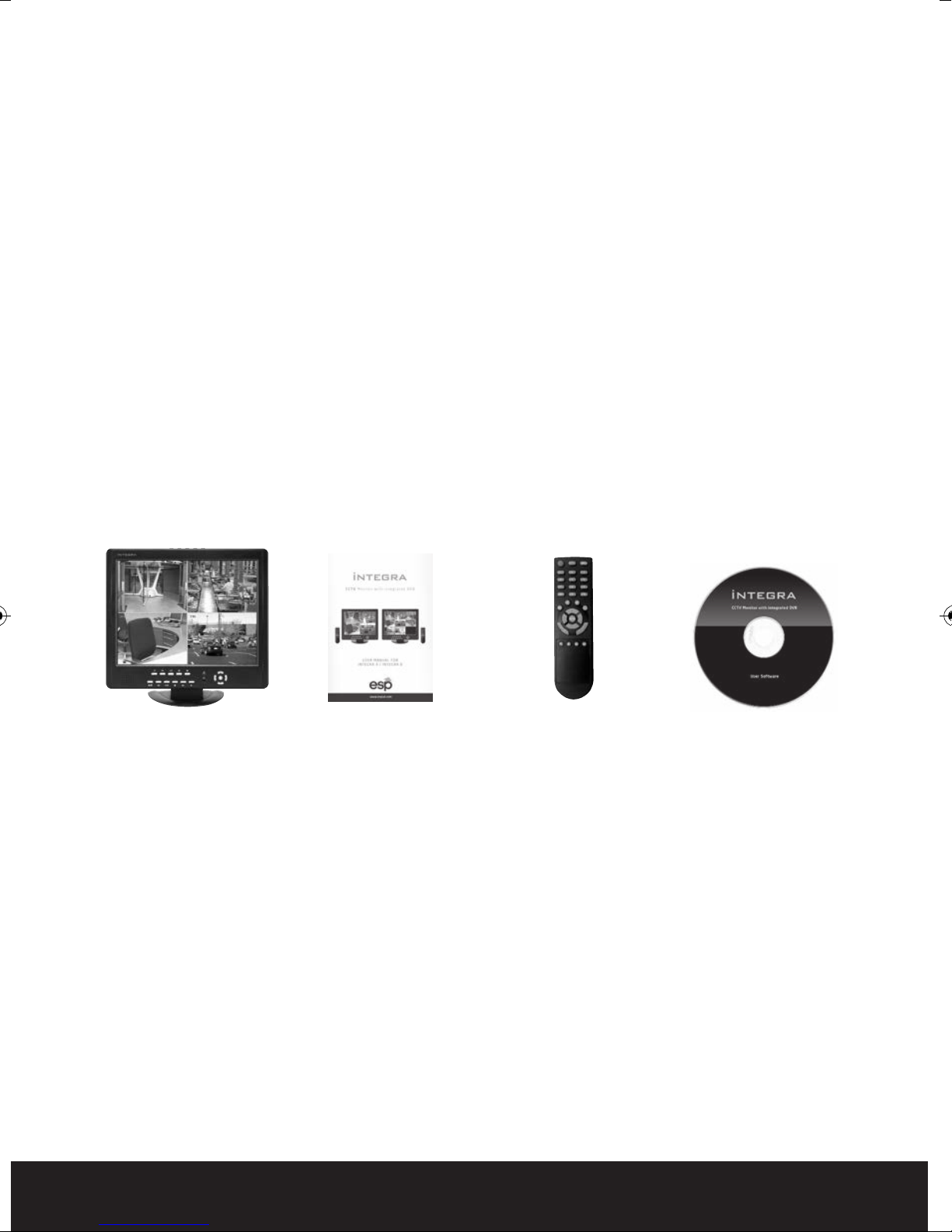
What is included
Integra c/w installed
hard drive
This quick start manual is intended as a guide to accessing the main features and
functionality of the integra. The intuitive menus offer further information and an
explanation of the full capability of the system is included on the enclosed CD.
Please get acquainted with the parts and accessories as well as the ways to use the
appliance as described in this instruction manuals. If you have any questions that cannot be
answered by either the quick start or full user guide, please contact your distributor or ESP
directly. Technical support +44 (0) 1527 515150
Getting Started Check-List
Before starting to work with your integra please make sure all relevant connections are
carried out correctly.
• Are the power and video in/out cables connected?
• Have you formatted the Hard Drive ?
• Are all cameras connected and powered ?
Installation manual Remote Control
Installation CD
3
Page 4

SAFETY INSTRUCTIONS
• Read these instructions and keep them in a safe place for future reference.
• Please refer all work related to the installation of this product to qualified service personnel
or system installers.
• Do not operate the appliance beyond its specified temperature, humidity or power source
ratings.
• Place the unit on a flat surface not prone to vibration or impact.
• Use the appliance at
below 85%.
• The input power source for this appliance is between 90 ~ 264 VAC, 47 ~ 63 Hz.
• Install the unit away from heat sources such as radiators, heat registers and stoves.
Installation of the unit near consumer electronics devices, such as stereo receiver/amplifiers
and televisions, is permitted as long as the air surrounding the terminal does not exceed the
above mentioned temperature range.
• Handle hard disk drives with care.
• It is possible to damage hard drives if they are moved while their motors are still running. To
allow the hard drive to spin down and park its heads, wait at least 10 seconds after
disconnecting power before moving the unit.
• To avoid shock and vibration damage to the internal hard drive, do not move the un
is plugged in.
• Do not place the unit in an enclosed area where the cooling vents are blocked or impede the
flow of air through the ventilation openings.
• Protect the power cord from being stepped on or pinched particularly at plugs and the points
where they exit from the apparatus.
• Do not drop metallic parts through slots. This could permanently damage the appliance.
Turn the power off im
• Handle the appliance with care. Do not drop or shake, as this may damage the device.
• Do not expose the appliance to water or moisture, nor try to operate it in wet areas. Do not
install the unit in an area where condensation occurs. Do not operate with wet hands. Take
immediate action if the appliance becomes wet. Turn the power off and
qualified service personnel. Moisture may damage the appliance and also cause electric shock.
• Do not use strong or abrasive detergents when cleaning the appliance body. When the dirt is
hard to remove, use a mild detergent and wipe gently.
• Do not overload outlets and extension cords as this may result in a risk of fire or electric shock.
• Please make a note of your settings and sav
change the system configuration, or when an unexpected failure or trouble occurs.
temperatures between 0oC ~ +45oC (32oF ~ 113oF) and humidity
it while it
mediately and contact qualified service personnel for service.
refer servicing to
e them. This will help when you are required to
Caring for the environment by recycling
When you see this symbol on a product, do not dispose of the product with
residential or commercial waste.
Recycling your Electrical Equipment
Please do not dispose of this product with your residential or commercial waste.
Some count
collect and recycle electrical and electronic waste items. Contact your local
authorities for information about practices established for your region.
ries or regions, such as the European Union, have set up systems to
4
Page 5
Controls
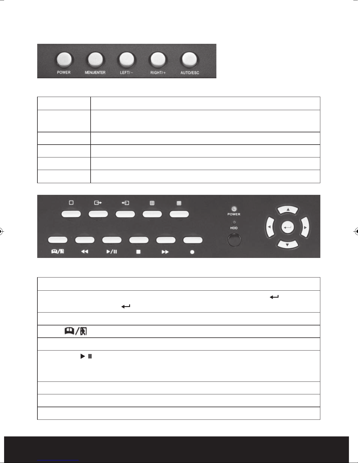
LCD MONITOR CONTROLS
Function Description
POWER Independent power switch for the monitor. Press the button for over 3 seconds to
turn off. DVR power not effected
MENU/ENTER Press the button to enter monitor menu settings
RIGHT/+ Move the prompt of the parameters on the screen or increase value.
LEFT/- Move the prompt of the parameters on the screen or reduce value.
AUTO/ESC Press the key to exit monitor menu settings
12
14
1
678910 11
2345
13
16
17
FRONT PANEL
1-5 — Select video channels to display on live monitor between individual channels or quad display.
14, 15, 16, 17, 18 – Use arrow buttons to move among the menu items. Press Enter (? ) to confirm
your choice. On live view the (? ) button is used as PTZ control key.
12, 13 Power LED ( Blue ) HDD LED (Red) – Confirms connection to the power supply and the HDD.
6 Menu – Access tool bar/Hide tool bar/Exit menu/Exit sub menu.
7 Rewind
8 Play/Pause /
Opens video search and playback menu. When the playback mode is activated, press this button to
play/pause playback.
9 Stop ■– Stop playback.
– Rewind video during playback.
??
1518
10 Fast Forward
11 REC ●– Start or Stop manual recording
??
– Fast forward video during playback.
5
Page 6

REMOTE CONTROL
In device operation, the enter key on the remote control or the front panel has the same
function as a mouse left click. The IR Range of the remote control is up to 10 meters.
The buttons on the remote control correspond 1-1 with the buttons on the front panel.
1
1 REC
Start or Stop manual recording.
2 Numerical Button
Use to select channel for live full screen display
2
56
4
8
12
10
13 14 15 16
3 Quad
Switch to quad mode
4 Menu (MENU/ESC)
3
7
911
Displays/exits the main menu.
5 Lock
If the password is enabled, press to logout of the system.
6 Mute ON/Mute Off
Turn on or turn off sound.
7 Spot View
Press to enable auto sequencing.
8, 9, 10, 11
Move selected item in menu.
12 ENTER
This button is used as the “enter” key in most functions or to
access PTZ mode on live view
13 Play/Pause
Opens video search and playback menu. When the playback
mode is activated, press this button to play/pause playback.
6
14 Stop
Stop playback
15 Rewind
Rewind video during playback.
16 Fast Forward
Fast forward video during playback
Page 7
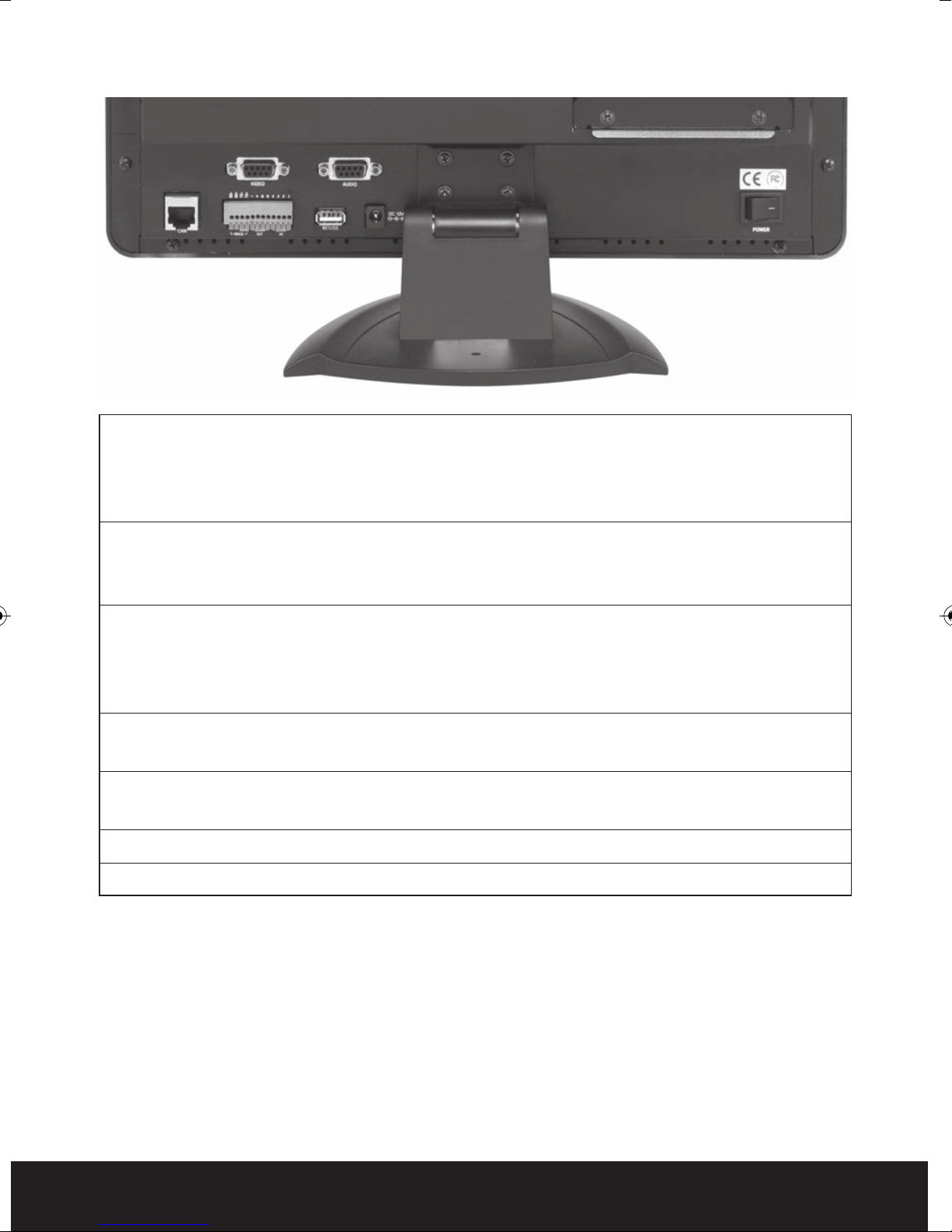
BACK PANEL
1/2 3
45 67 8
1/2 Video Input/output Connectors
4 channel video input BNC (1Vp-p, 75Ω) plus single video output for integra 4,
8 channel video input BNC (1Vp-p, 75Ω) plus single video output for integra 8.
All inputs/outputs via supplied multi channel converter
3 Audio Input / Output Connectors
4 channel audio input / 1 channel output, RCA (2Vp-p, 600Ω) for integra 4,
8 channel audio input / 1 channel output, RCA (2Vp-p, 600Ω) for integra 8,
4 Alarm Input / output
(ALARM IN 1-4, 5-6 Ground) For connection to external sensor devices
(ALARM OUT 7-8) For connecting to external alarm devices
(PTZ 9-12)RS-422 / RS-485 Connector For connecting PTZ camera control
5 Ethernet Connector
RJ-45 10/100 Base-T Ethernet network
6 USB ports
Connection for mouse ( Rear ) and backup stick (side)
7 Power Input Socket (12V DC)
8 Power Switch
7
Page 8
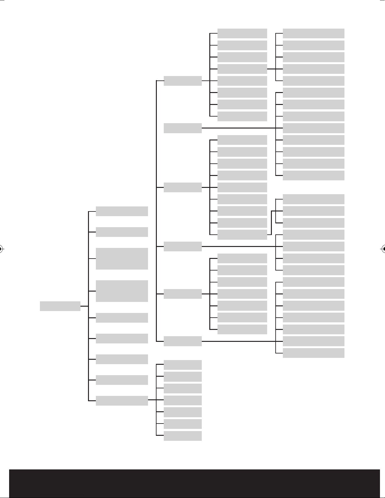
INTEGRA MENU TREE
Language
Add User
System Settings
Play
System
Record
Video
Video System
Time
User
HDD
Volume
Maintenance
Information
Video Channel
Name
Position
Live
Video Audio
Video Colour
Record Time
Video Margin
Video Setup
Change Password
Delete User
Local Permission
Remote Permission
Record Channel
Record
Record Bitrate
Record Resolution
Record Framerate
Record Audio
Record Packtime
Record Mode
VGA Resolution
Roll Time
Area Covered
Network
TOOL BAR
Manual REC/
STOP Manual
REC
MUTE ON/
MUTE OFF
Keylock
PTZ
Auto Sequence
EZOOM
Advance
Network
Alarm
PTZ
PIP*1
PIP*2
VO Switch
Quad
6 Show
8 Show
Channel
I/O Alarm
HDD Loss
HDD Full
Video Loss
Alarm Action
Motion Detect
DDNS
Email
Mobile
Channel
Protocol
Baud Rat
Data Bit
Stop Bit
Parity
Address
8
9 Show
Page 9
Getting Started and the Main Screen
IMPORTANT - FORMATTING HARD DISK DRIVE
Before you can record onto your HDD it should be formatted by integra as standard PC
formatting is not compatible. To format the HDD enter the main menu – system settings
– HDD – Format HDD. The format process can take several minutes.
Switch on your DVR and wait for the system program to load. If you have not yet formatted
the i
nstal
led hard disk drive , or the integra didn’t read the HDD, or there is no space of the
HDD to record, it will display an icon “ ? ” in the video preview interface. You must format the
HDD in the DVR before first use. Please see above.
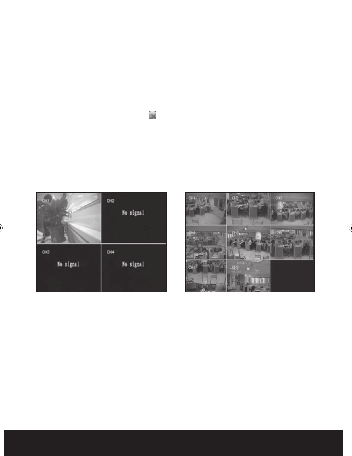
THE MAIN SCREEN
The standard layout is four or nine windows ,depending on the model ,evenly distributed
over the screen. From the main screen you can access menu options an
channel views, displaying either all channel feeds simultaneously or a full-screen view of a
selected channel.
d switch among
?
Integra 4 integra 8
DISPLAYING A SINGLE CHANNEL
In the multiple screen view, you can make a particular window active by left-clicking on it
once with a mouse, or navigating to it using directional buttons. If an audio output device is
connected to this channel, you can monitor b
In order to return to the multi-screen view you could either double-click on the screen again
or press the single/multiple view button either on the remote control or the front panel.
oth audio and video feeds.
9
Page 10
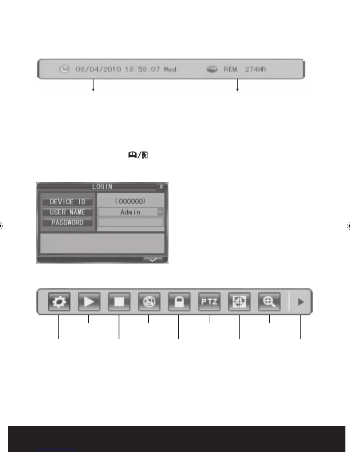
STATUS BAR
To display the Status Bar single right-click on the screen. The status bar displays useful
information such as time and date settings plus available hard disk space.
System time Approximate Remaining Hours of HDD recording
Right click again to move on to the main menu bar or right click twice to return to main live view.
LOGIN SCREEN ( WHEN PASSWORD ACCESS IS ENABLED )
In live view, press the button “ ” twice or double-click twice the right mouse key. The
login window will appear if password access is enabled. Select user name and user password
via numeric key-board to access the main menu.
The default password for the main
administration user is “Admin” and the
password is “888888”. For system security
you can change the password of admin and
add other usernames with passwords
can have allocated restricted user rights.
th
at
NB . Passwords are case sensitive.
MAIN MENU (INTEGRA 8 SHOWN IN EXAMPLE)
SYSTEM
SETTINGS
PLAY
MANUAL
REC / STOP
MANUAL REC
MUTE ON/
MUTE OFF
KEYLOCK
PTZ
EZOOM
SEQ ADVANCE
10
Page 11

System
configuration
Search, playback and
backup of recorded files
MANUAL REC/STOP MANUAL REC:
Click the [MANUAL REC] button to start manual recording. Click [STOP MANUAL REC] menu or
press [n] button to stop manual recording.
KEYLOCK:
If the password is enabled, click “KEYLCK” to logout the system.
? PTZ:
Enters PTZ control.
? AUTO SEQUENCE: Click to enable auto sequencing, the channels with images will be
displayed in sequence . Channels without images or with sequence display disabled won’t
display. To interrupt auto sequencing, press any button or click the mouse while in auto
sequence mode.
? EZOOM: Click “EZOOM” to enter into zoom mode, and then click left key and drag to select the
area that you want to magnify. Right click to exit.
Click the right arrow “ADVANCE” button to display the advanced display functions depending
on model.
HIDE
ADVANCE
PIP 1
PIP 2
VO
SWITCH
QUAD
6 WAY
9 WAY
8 WAY
SYSTEM SETTINGS
Contains settings for most general system configurations such as recording , Video display ,
network, alarm and PTZ .
Note: In order to validate sub-menu settings it is important to select to confirm
actions. Failure to select before exiting will mean changes have not been
stored.
Note: The green arrow shown on many sub-menu screens will return settings on that
sc
re
en to factory default . Do note use the green arrow to exit the screen . To exit the
screen after saving parameters click the cross in the top right hand corner.
11
Page 12

Recording
There are three ways of recording live video .Manual recording, scheduled recording and
motion recording.
Manual recording
Simply select manual record from the main menu bar ? or the remote control or front
panel. If the recording schedule is in conflict with manual recording, the manual recording
will be processed first until stopped.
Scheduled recording
Within system settings in the ma
then left click on the arrows below to display the record schedule set up screen. The record
schedule can be set up by channel , day and time and either normal or alarm / motion
recording.
Motion recording
Within system settings in the main menu select alarm then select motion . Each channel can
be configured separately for motion on , sensitivity
trigger . Remember to select the tick ( save parameter ) after configuring all channels or
settings will be lost.
Recording status display
The top right corner of each channel image features the following status icons:
? Icon indicates that the channel has detected motion in the motion detection mode.
? Icon indicates that the channel has detected sensor alarm i
menu select record then record mode . Select schedule
in
,
motion detection area and activity upon
e alarm mode.
n th
Red dot indicates that the channel is running in the mode of recording.
12
Page 13
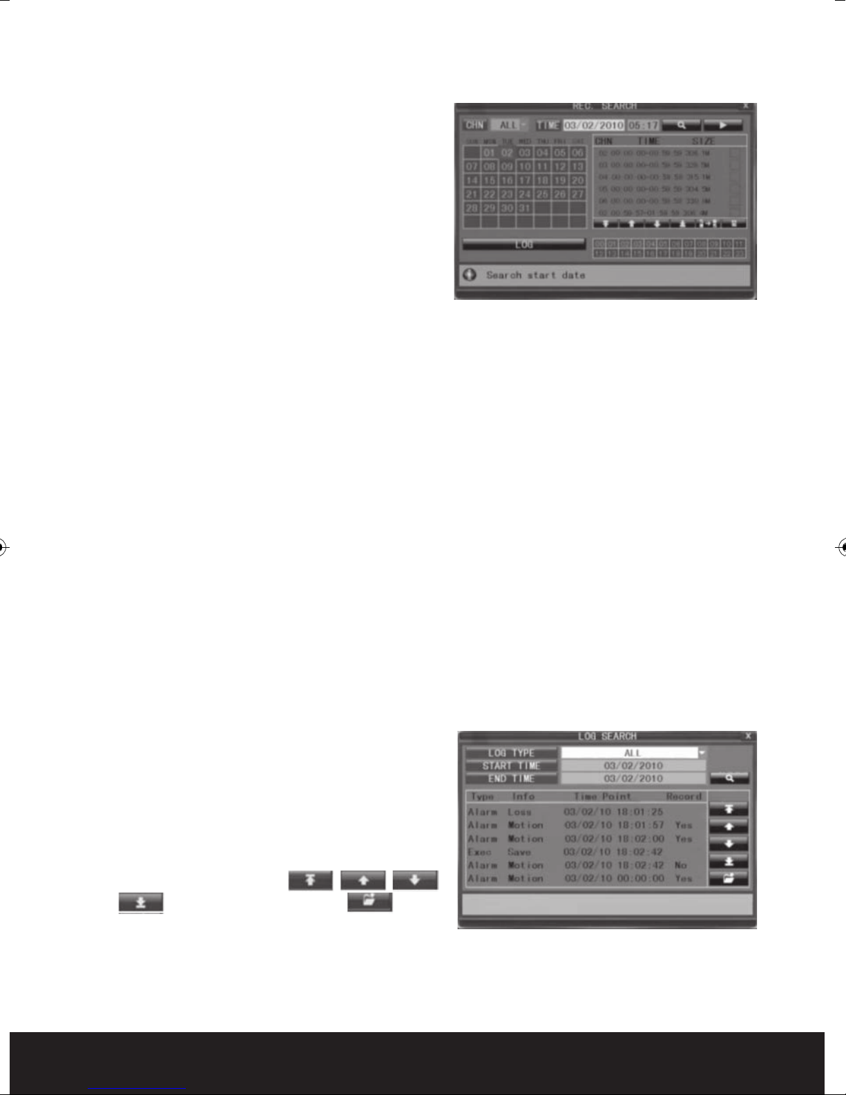
Playback
To play back recordings select play from the main
menu or press the play button on the front panel
or remote control to access the record search
playback screen.
There are various methods of searching for
recordings.
Playback by specific date
Input the time and date of the desired viewing
period checking date and time, and click the
“play” icon. It is possible to select all channel or single chan
Playback by calendar
Input the desired approximate search date and click the search icon to see the recording
status on this date.
There are five channel options: CH1, CH2, CH3, CH4 and ALL. Press【Enter】and you can
change the channel to be displayed on file listing.
nel p
layback.
Recordings for the relevant month will be shown in the calendar block. Recording status for
each day will be displayed .Green
recording. Click any date to search the recording status of that day. Select any period within
the day to begin playback.
Playback by file list
Input the approximate searching date and click “search” to view the recording status. Choose
an entry within the file listing to play back
Playback by log
Select log search from the record search menu.
Select a log
select the search icon to display the log of
recorded files. Use the up and down arrows to
search through the log
Push “Search” button after the setting of log
time and type, and the system will display the
required log in the list. Click , , ,
and to switch page, and click to
save the log list to USB disk.
typ
e and start and end time then
al recording, Red alarm recording and Grey no
norm
13
Page 14
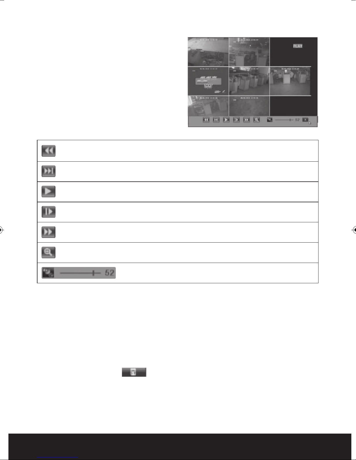
PLAYBACK CONTROL
In the playback mode you can see the playback
control panel as well as the date and time of the
played file.
Fast rewind, the available speeds are 2x, 4x, 8x, 16x, 32x and 64x.
Slow forward, the available speeds are 1/2x, 1/4x and 1/8x.
? Play
Pause/Frame-by-frame view
Fast forward, the available speeds are 2x, 4x, 8x, 16x, 32x and 64x.
? Ezoom: Right click to enter zoom mode. In zoom mode left click and drag to create a
zoom area. Right click to exit.
? Audio volume adjustment.
Video Backup
Storing captured recoding on a USB stick is done through the playback menu.
a) Insert a USB stick into the USB port on the right hand side of integra.
b) Search for files to be recorded
c) Select the files for backup from the file listing box on the right hand side o
search screen by selecting the tick box next to each required file.
d) Select the back up icon ? located at the far right hand side of the menu bar below
the file listings to start back up
f th
e record
Integra only supports the FAT32 file system for USB flash drives and HDDs
14
Page 15

PLAYING BACKED UP VIDEO ON A PC
To play back stored recorded files from a USB stick to a PC you will need to firstly install the
HSplayer program from the enclosed CD. Place the CD in your PCs CD drive. Within the drive
directory locate the folder marked “Player”. Within the folder locate the file marked HSplayer
. Copy , send or drag this application to your selected folder or desktop. Double
click the HSplayer icon in your selected location to open the player screen.
Maximize
the window
Minimize
the Window
Close the
Window
Open
Capture Play
Setting
Click to open a file to play from your USB stick.
You can capture and store still images from the file being viewed by left clicking the capture
icon at any time . Before capturing stills set the storage path in the settings menu to stor
th
e images in the desired folder on your PC.
Mute
Next frame Volume slide
e
15
Page 16

Remote viewing
Remote viewing and control of integra is possible via local network , remote PC or most 3G
mobile phones .Before attempting any remote connections the integra must first be set up
on a local connection to the internet.
NETWORK SETUP
Select network from the system setting menu and then select network again from the sub
menu.
UPNP: Universal plug and play. If your router supports UPNP turn th
function on to allow integra to automatically map its port to get a
mapped IP address. If your router does not support UPNP you should
select UPNP off and manually enter the settings.
TYPE: Select here the network connection type DHCP, PPPOE or Static
MEDIA PORT: Transfersvideo data between client and device.
WEB PORT: Sets up the port of IE browser via HTTP. Default: 80. If the web port is
chan
ged th
http://192.168.15.145:8088
SETUP PORT: This port is fixed and you can’t modify it, the value is 8000.
DNS: input IP address for the net domain name sever,
Static IP address set up
IP ADDRESS: input IP ADDRESS of the integra connection.
The format of the input is xxx.xxx.xxx.xxx . If the IP address has only
two numbers x 3 plus three numbers enter 0 ( zero
two numbers. ie 0xx.0xx.0xx.xxx
SUBNET MASK: input the subnet mask of the integra connection
e new port No. should be added behind IP,
) b
efore each set of
is
GATEWAY: input the gateway number of the integra connection
PPPOE SETUP
Select PPPOE from type menu
Media port : Enter media port . Default 9000
WeB port : Enter HTTP port . Default 80
PPPOE User : Enter user name supplied by ISP supplier
PPPOE password : Enter PPPOE password supplied by ISP sup
16
plie
r
Page 17

DDNS SETUP
From the main network menu select DDNS
Select DDNS on
Select the DDNS server from three options
3322
DYNDNS
Perfecteyes
HOST NAME: Input the name of the host server.
USER NAME: Input the name of the user.
PASSWORD: Input the password.
EMAIL SETUP
Images created by alarm events can be sent via e-mail directly from integra. To send e-mail
settings must be configured within e-mail in the main network menu an
selected as an action following an alarm event with the alarm setup.
SSL: SSL is a security link transport protocol. You can encrypt your
communication info using SSL to prevent hackers from monitoring your
email and communication data. This function is not available when
using Gmail as a mail server.
d e-mail must be
Interval: This indicates the interval for sending email, including 5s – 3m
SMTP
SMTP: enter the server IP address
Sender: enter the sender’s email address. The email address should be
Receiver: enter the intended receiver’s email address.
Po
rt: enter the sender port of the SMTP server. Generally the SMTP port
value is 25, but there are exceptions, for example, the SMTP port of
the G-mail server should be 465.
associated with the SMTP server used.
MOBILE PHONE REMOTE MONITORING
Mobile remote viewing directly from integra can be set up with many 3G enabled mobile
phones . To enjoy this function the integra must be first connected and setup correctly with
the internet . Please see network set up options above .
Move the cursor to【MOBLE SETUP】(the icon will be highlighted when selected), and press
【Enter】to enter into the setting interface.
SERVER PORT : Enter a server port number b
is 10510
etween 1024 and 65535 default setting
NETWORK TYPE: Enter the mobile network capability .
Note: You can only see one channel at one time when viewing from a mobile phone.
The speed of the display depends on the speed of the internet connection.
17
Page 18

Web Browser Operation
FEATURE
Install the software through the IE browser of OS to operate the network remotely and
conveniently. DVR supports C/S, B/S, and access in LAN and WAN. It also supports IP and
domain name visiting.
RESTRICTION CONDITION
To ensure a stable connection we recommend Windows XP or Windows Vista operation
system, and IE 6.0 or IE 7.0 browsers.
NETWORK SECURITY SETTING
Prior to control installation, please program the network security level by using the following
operations:
(1) Open the IE browser and click [Tools? Internet
Options].
(2) Choose the “Security” label in the dialogue box.
(3) Click “Customization level” to enter into the
security setting.
To set the ActiveX control and plug-ins. Select
the following options
√ ActiveX control auto-prompting
√ Run the script of the Acti
marked to be that can safely implement the
script.
√ Implement initialization and run the script of the
ActiveX control which is not marked to be that
can safely implement the script.
√ Binary system and the script behavior
√ Download the unsigned ActiveX control
√ Download the signed ActiveX control
√ Perform the ActiveX control and pluggable unit
It’s extremely importation to “enable”
above.
Prompt: Before control installation, please turn
off any fire wall and anti-virus software.
X control which is
ve
the
items
18
Page 19

CONNECTION SETTING
The remote access for integra should be carried out
through the network. In the local area network
connection, the IP address of the client computer
must be in the same network section with that of the
integra. When using a wide area network connection,
ensure that both client and host can visit the public
network, and connect through the IP address or the
dynamic domain name. The fol
on the connecting and setting method for a local area
network.
Step 1: Right click on “Network neighborhood” and
click “Attribute” to open the “Network
connection”.
Step 2: Double click to open “Local connection”.
Step 3: Click “Attribute”.
Step 4: Double click “Internet protocol (TCP/IP)”.
Step 5: Examine the IP address, subnet mask, and
default gateway on the PC.
g will mainly focus
lowin
Step 6: Set the corr
mask, and default gateway on the DVR (refer
to 5.5.5 Network Setup). If the subnet mask
and default gateway on DVR are the same
with those of the PC, then the IP address
must be in the same network section but
cannot be the same with the used one.
Otherwise, it will cause IP address conflicts.
Take the figure above as an example, the IP
address should be: 192.168.0.X, wherein,
not be 40 or 1 (including other IP
can
addresses currently being used), and cannot
surpass 255, the subnet mask is
255.255.255.0, and the gateway is
192.168.0.1.
espon
ding IP address, subnet
X
19
Page 20
CONTROL DOWNLOAD AND INSTALLATION
After finishing the aforementioned settings, open the IE browser, input http the setting IP
address of the integra and confirm. If the http port of DVR setting has been changed (not
80), you must add a colon and port number .
“If your browser does not support the ActiveX to download, please click here”, the network
will download and install the control automatically.
Afte
r connecting to the internet, IE will automatically download the file to PC as follows.
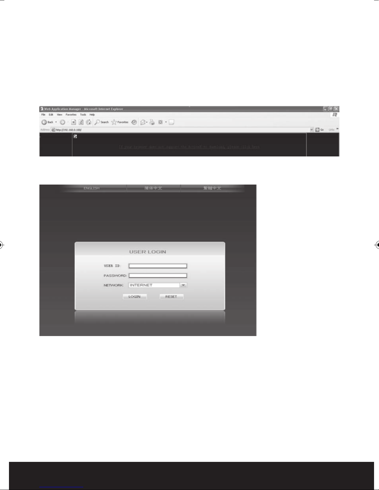
The system will automatically enter the integra user interface as follows.
Select English interface then input the chosen password if enabled.
USER ID: Input user name. The administrator has all authorities, but common users
may have limited usage authorities set by the administrator.
PASSWORD: The password is a
NETWORK: LAN/WAN
Note: If you connect the device in WAN, the IP should be a public IP.
OPERATION INTERFACE
Options in the main interface include LIVE, REPLAY, REMOTE SETTING, LOCAL SETTING and
LOGOUT. Click any option to access.
20
e same as the password of Device.
s th
Page 21
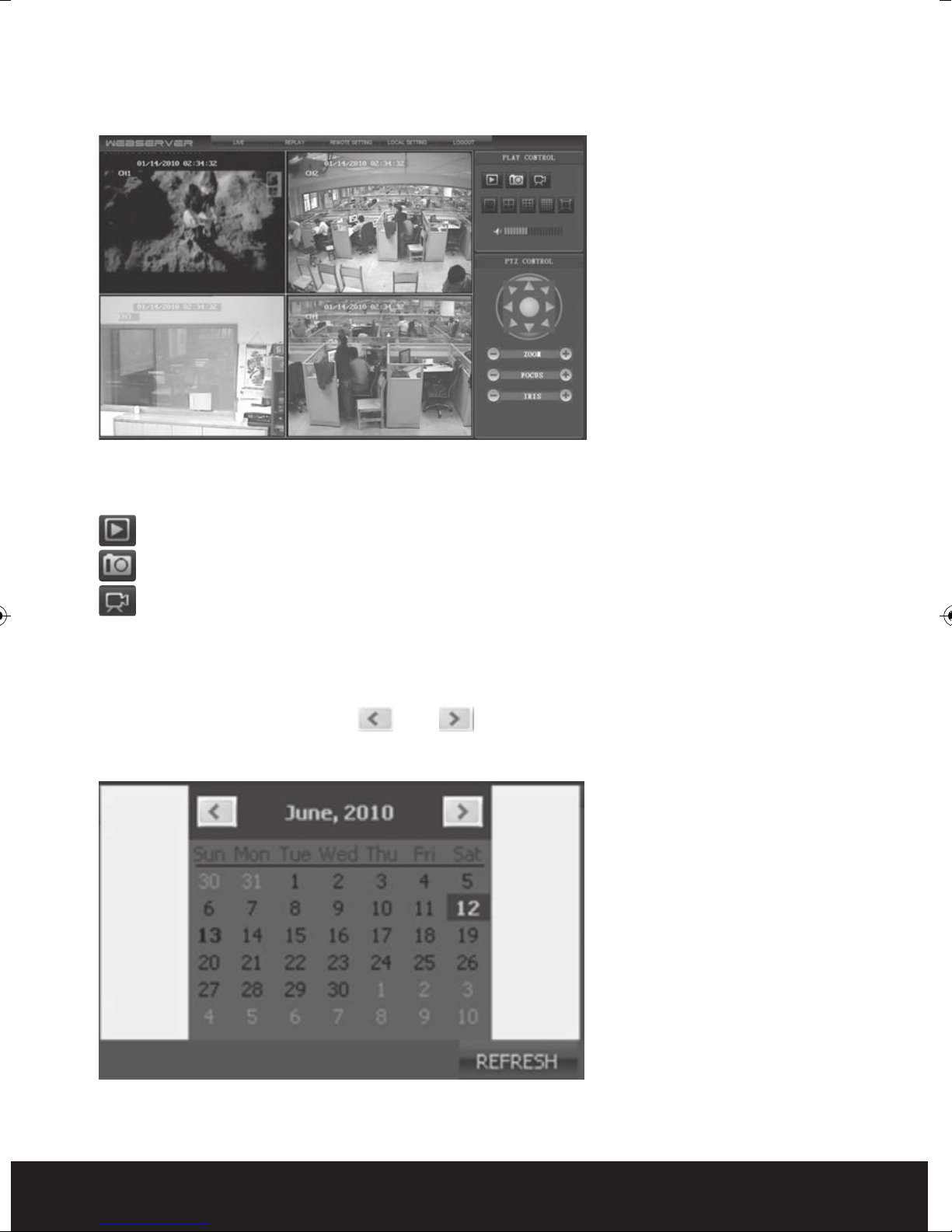
LIVE
Click [Live] to enter into the interface as follows.
CONTROL
Move cursor to the icons, which will become highlighted when selected.
Connect all windows or disconnect all windows.
Capture a single image .Default save path is “c:\DVR\BACKUP\”.
Quick start recording all channels.
REPLAY
Click “REPLAY” to enter playback mode
Click right of calendar interface ? and ? , to set the month for search
“REFRESH” at the calendar interface to display the recording information of current month.
ing; click
21
Page 22
The highlighted date indicates that video was recorded on that day. Click on a date to search
the recording file list of that day. For example, the above fig shows that June, 12th, 13th
have recorded video when it shows on bold, and current search date is June 12th.
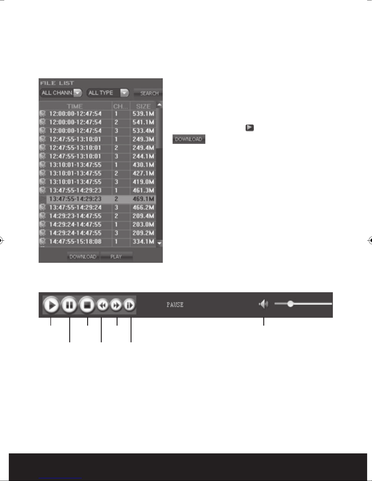
Select channel and type at the bottom of the calendar. Click “SEARCH” and the result will
display as follows.
?
INSTRUCTION OF TOOLBAR
Double click one of the l
iste
d recorded video to
playback. Or select one of the listed recorded
video and click the button [PLAY] to playback. The
file icon will change to ? .
? The user can download files on PC, and
save them to HDD for backup or play. Download
file format is AVI file.
Play Volume Control
Pause
Stop Fast
Play
Slow
Play
Single
Play
REMOTE SETTING
Click [Remote Setting] to enter into setup interface, this interface includes record, alarm,
PTZ, network, advan
ced and system information six menus.
22
Page 23

Encode Setting
Click [Encode Setting] – [Video Para] to
enter into setup interface. User can
adjust recording parameters (resolution,
quality and frame rate) for each channel
remotely via net-viewer.
?
Record Setting
Click [Record Setting] to enter into the
menu interface, user can select “on/off”
for each channel, and adjust recording
parameters (audio, pack time, REC mode
and REC schedule) remotely via ne
viewe
r.
t-
?
Alarm Setting
Click [Alarm Setting]-[Device Alarm] to
enter into setup interface.
Click [Alarm Setting]-[Channel Alarm] to
enter into setup interface. User can set
up alarm event types; also can set I/O
alarm for each channel, motion detection
alarm, motion area, motion sensitivity,
alarm out time, buzzer time, pre REC time
and post REC time.
?
PTZ Setting
Click [PTZ Setting] to access setup
interfac
remotely using the same methods as in
the local DVR setup.
ser can setup PTZ parameters
e. U
?
23
Page 24
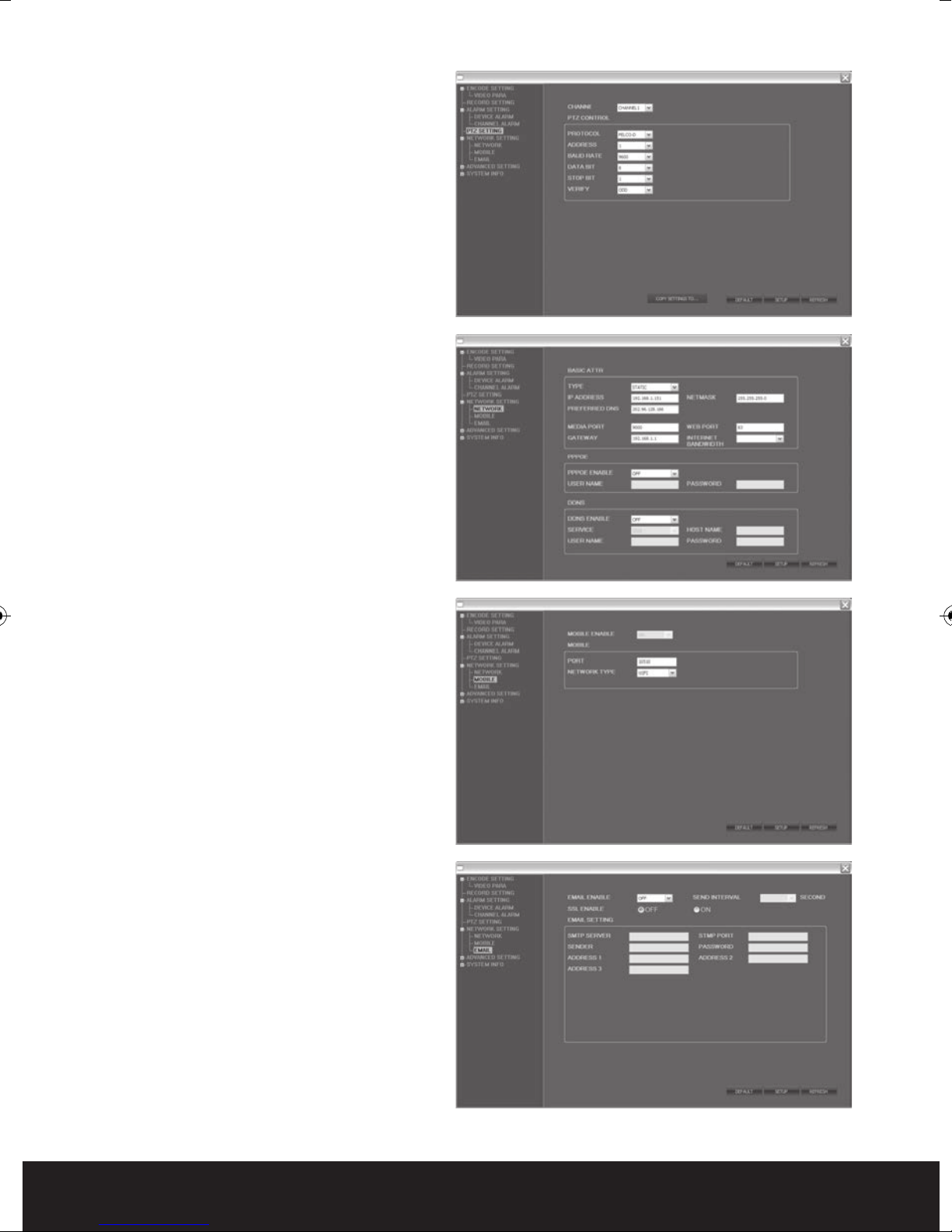
Network Setting
Click [Network Setting] - [Network] to
enter setup interface. The menu allows
user to set a lower bandwidth for
Internet video transmission.
Click [Network Setting] - [Mobile] to
enter setup interface.
Click [Network Setting] - [Email] to enter
setup interface.
User can setup network parameters
using the same methods as in the local
DVR setup.
24
Page 25

System Setting
Click [Advanced Setting] - [System
Setting] to enter setup interface. The
menu allows user to set daylight saving
time.
?
System INFO
Click [System INFO] - [Version INFO] to
enter setup interface. Here user can
check the device’s ID and software
version.
Click [System INFO] - [HDD INFO] to enter
setup interface. Here user can check HDD
state, total size of HDD and free size of
HDD.
?
User Manager
C
lick [User Manager] - [ADD OR DEL] to
enter setup interface. This interface
could only been seen by administrator
when password is available.
Administrator can add new user or delete
any user.
25
Page 26

Click [User Manager] - [MODIFY
PASSWORD OR PRI] to enter setup
interface. This interface could only be
seen by administrator when password is
available. Administrator can change
password, local authority and remote
authority.
LOCAL SETTING
Click [Local Setting] to enter setup
interface. User can setup the save path
for local setting. “Record save path” is for
recording, “Frame save path” is for
capture and
download. Click the button to
setup save path.
e save path” is for
“Fil
?
LOGOUT
Click [Logout] to log out of the system.
26
Page 27

Mobile Phone Support
A state-of-the-art feature of this DVR device is transmitting live feed from the CCTV
cameras to your mobile phone, so that you can have ‘on the go’ access to your surveillance
system from virtually anywhere in the world. Currently, there are a limited number of phones
that can support this feature: Windows CE Mobile, Symbian S60 3rd Edition OS, Apple
IPhone, Andriod and Blackber
APPLE IPHONE 3GS AND 4 AND ANDROID
( Note remote viewing software and installation instructions for remote viewing via
Blackberry phones can be found on the enclosed CD )
Mobile viewing on a suitable 3G phone is simple via a bespoke viewing APP
developed for integra .Download the Mobileye APP from the relevant APP store
directly to your phone.
ry.
Launch the APP on your phone then select settings ( botto
rig
ht hand corner )
Server IP: enter IP address of the integra
Note : If the IP adress entered into the integra network
settings is a 0xx.0xx.0xx.xxx format do not enter the zeros.
Port: enter the mobile port of the integra Default 10510.
User name : enter your integra user name
Password : enter your integra password
Note passwords are case sensitive.
Click back to enter control screen.
Click bottom lef
In control screen you can select cameras to view.
Operate PTZ and store snapshots
t “p
lay” to connect to integra
m
27
Page 28

Technical specification
INTEGRA 4
Video Format PAL
Video Format H.264 Baseline Compression
Video Input BNC 4 Input / 1 Output
Audio Format G.726 8Kx16bit ADPCM Mono
Audio Input RCA 4 Input / 1 Output
Alarm Type Motion detection, Sensor Input, Relay Output,
Video Loss
Sensor In/Out 4CH Input / 1CH Output
Display Frame Rate Each Channel PAL25 FPS, NTSC30 FPS
LCD Monitor 15” Color LCD, 1024x768, 4:3, 450:1, 150nit, CCFL
Playback Resolution (CH1) 25fps/(CIF) 25fps/(halfD1),12fps/D1
Record Frame Rate 100FPS@CIF100FPS@halfD150FPS@D1
Record method Power-on Auto Record, Scheduled Record
(Manual Record, Motion Detection, Sensor Trigger)
Support Privacy Mask
HDD Interface SATA Interface support 1000GB
Network Protocol TCP-IP/ DHCP / DNNS / PPPoE / E-Mail
Network Function IE Browser Live Monitor, Configuration,
Download Video Mobile Phone Surveillance
USB 2.0 Interface Mouse / Portable Mobile HDD/ Flash Drive/
DVD Burner/ Firmware Upgrade
Playback Method Normal Play, Fast Forward, Rewind, Single Step
Network Interface RJ45 10M/ 100M Ethernet Auto Detect
PTZ Protocol PELCO-P, PELCO-D
Video Backup AVI
Power Adapter DC 12V Adapter
Power Consumption 10~15W
Operating Temperature 0~+40
Operating Humidity 10%~90% RH
Dimensions 360 x 360 x 160mm (WHD) inc. stand/base
28
Page 29

Technical specification
INTEGRA 8
Video Format PAL
Video Format H.264 Baseline Compression
Video Input BNC 8 Input / 1 Output
Audio Format G.726 8Kx16bit ADPCM Mono
Audio Input RCA 8 Input / 1 Output
Alarm Type Motion detection, Sensor Input, Relay Output,
Video Loss
Sensor In/Out 4CH Input / 1CH Output
Display Frame Rate Each Channel PAL25 FPS, NTSC30 FPS
LCD Monitor 15” Color LCD, 1024x768, 4:3, 450:1, 150nit, CCFL
Playback Resolution (CH1) 25fps/(CIF) 12.5fps/(halfD1),6.25fps/D1
Record Frame Rate 200FPS@ CIF,100FPS@halfD1,50FPS@D1
Record method Power-on Auto Record, Scheduled Record
(Manual Record, Motion Detection, Sensor Trigger)
Support Privacy Mask
HDD Interface SATA Interface support 1000GB
Network Protocol TCP-IP/ DHCP / DNNS / PPPoE / E-Mail
Network Function IE Browser Live Monitor, Configuration,
Download Video Mobile Phone Surveillance
USB 2.0 Interface Mouse / Portable Mobile HDD/ Flash Drive/
DVD Burner/ Firmware Upgrade
Playback Method Normal Play, Fast Forward, Rewind, Single Step
Network Interface RJ45 10M/ 100M Ethernet Auto Detect
PTZ Protocol PELCO-P, PELCO-D
Video Backup AVI
Power Adapter DC 12V Adapter
Power Consumption 10~15W
Operating Temperature 0~+40
Operating Humidity 10%~90% RH
Dimensions 360 x 360 x 160mm (WHD) inc. stand/base
29
Page 30

LIMITATION OF LIABILITY
This users’ manual is supplied ‘as is’, with no warranties, be it expressed or implied,
including, but not limited to, the implied warranties of merchantability, suitability for any
exact purpose, or non-infringement of any third party’s rights.
This publication may include technical inaccuracies or typos. The manufacturer holds the
right to introduce any changes to the infor
including but not limited to, improvements of the publications and/or related to the product,
at any time, without prior notice.
mation
DISCLAIMER OF WARRANTY
The supplier shall not be liable to any party or any person, except for replacement or
reasonable maintenance of this product, for the cases, included but not limited to the
following:
contained herein, for any purpose,
Any damage or loss, includ
exemplary use arising out of or related to the product;
Inappropriate use or negligence of the user in operation of the product, resulting in personal
injury or any damage;
Unauthorized disassembly, repair or modification of the product by the user;
Any problems or consequential inconvenience, loss or damage, caused by connecting this
pro
duct to d
Any claim or action for damages, brought by any photogenic subject, be it a person or
organization, due to violation of privacy whereby the surveillance picture and/or saved data
becomes public or is used for the purpose other than surveillance.
evices of the third parties;
g but not limited to: direct/indirect, consequential, special,
in
30
Page 31

31
Page 32

Elite Security Products
Unit 7, Target Park, Shawbank Rd
Lakeside, Redditch B98 8YN
Telephone: 01527 515150
email: info@espuk.com
 Loading...