

Page 1

www.esavep.com
Air source heat pumps
Installation and user
manual
ESP HT 9kW
ESP HT 12kW
ESP HT 15kW
Page 2

1.0 Preface
2.0 System Overview
2.1 General Information
2.2 Specification Table
2.3 Dimensions and Scale
2.4 Performance Graph (COP)
3.0 Installation & Maintenance
3.1 Cautions & Warnings
3.2 Transit
3.3 Installation Position
3.4 Securing the Unit
3.5 Water Loop Connection
3.6 Water Pump
3.7 Power Supply Connection
3.8 Power Cable and Switch
3.9 Normal Heating and Cooling
3.10 Unit Commissioning Checks
3.11 General Maintenance
3.12 Operating notes for end user
3.13 After sales service & Information
4.0 Controls and Operation
4.1 The Unit controller display
4.2 Functions and associated buttons
4.3 Saving Controller Parameters
4.4 Installing a remote control
4.5 Symbol meanings
4.6 Parameters
4.7 Weather Compensation Data
5.0 FAQ & Troubleshooting
5.1 Support
6.0 Appendices
Appendix 1 Wiring Diagrams
Appendix 2 Installation Engineer’s Details.
Appendix 3 Installation and Commissioning Certificate
2 of 52| Earth Save Products-ASHP PASRW030B-D-PS
V 1.8 PASRW040B-D-PS
PASRW050B-D-PS
Page 3
WARNING !
READ THIS BEFORE
INSTALLING
THE UNIT.
The installation of all un-vented water heating systems above 15
litres (this includes the ESP Hot Water ASHP’s) MUST
comply with local area Building Regulations. It is a legal
requirement that the local Building Control Officer be notified
of any proposed installation.
UK regulations require an appropriately sized expansion vessel
(internal or external) to be incorporated, safety devices to prevent
the stored water exceeding 100°C, and pipe work to convey
discharged hot water safely away from the safety devices.
Furthermore, the installation must be carried out in
accordance with this manual and by an engineer who has
successfully completed a recognised course in the
installation of un-vented heating systems such as CITB. The
guidance contained in the Good Practice Guide should be
followed. Failure to fit the unit correctly and in accordance
with regulations may affect its safety, efficiency and WILL
invalidate any guarantee.
THE UNIT MUST BE INSTALLED, COMMISSIONED AND
MAINTAINED BY A COMPETENT INSTALLER IN ACCORDANCE
WITH BUILDING REGULATION G3 (ENGLAND AND WALES),
TECHNICAL STANDARD P3 (SCOTLAND) OR BUILDING
REGULATION P5 (NORTHERN IRELAND) AND THE WATER FITTING
REGULATIONS (ENGLAND AND WALES) OR WATER BYELAWS
(SCOTLAND). FOLLOWING INSTALLATION AND COMMISSIONING,
THE OPERATION OF THE UNIT SHOULD BE EXPLAINED TO THE
3 of 52| Earth Save Products-ASHP PASRW030B-D-PS
V 1.8 PASRW040B-D-PS
PASRW050B-D-PS
Page 4

1.0 Preface
Congratulations on purchasing your ESP air source heat pump (ASHP). It will
give you years of trouble free heating and help reduce your carbon footprint.
ESP ASHP units are built using the highest quality components and the latest
design and technology.
Please read this manual:
It is important that you read this manual and familiarise yourself with the
technology and controls so that you can get the best out of your unit. You
should keep this manual safe and ensure that it is available to engineers that
perform any installation works or maintenance.
Installation:
Please make sure that your ASHP is only installed by a suitably qualified
engineer and in accordance with this manual. If this is not done, it may
invalidate your warranty.
Warranty:
All ESP ASHPs are covered by the warranty contained in the ESP Terms and conditions
of Business a copy of which will have been provided to you prior to your purchase.
YOUR INSTALLATION ENGINEER MUST COMPLETE THE TABLE IN APPENDIX 2
– PLEASE ENSURE THAT THIS IS DONE AND THAT CONTACT DETAILS ARE
CORRECT AND CLEAR.
YOUR INSTALLATION ENGINEER SHOULD ALSO COMPLETE AND SIGN
APPENDIX 3 AND THIS INSTALLATION AND COMMISSIONING CERTIFICATE
SHOULD BE PROVIDED BY THE INSTALLATION ENGINEER AS PART OF THE
HANDOVER PACKAGE. THE CERTIFICATE SHOULD BE KEPT WITH THE UNIT
DOCUMENTATION AND ALWAYS HANDED TO ANY NEW OWNER OR
OCCUPIER OF THE INSTALLATION ADDRESS.
4 of 52| Earth Save Products-ASHP PASRW030B-D-PS
V 1.8 PASRW040B-D-PS
PASRW050B-D-PS
Page 5

Pictures and Drawing:
The pictures and drawings in this manual are for information only. The
manufacturer reserves the right to make modifications to the product
without prior notification to the end users.
Children:
You should not let children operate the unit or play close to it when in
operation. The unit has a fast moving fan and, whilst every effort has been
made to ensure that it is not accessible, children may try to put objects in to
it – this can cause injury and seriously damage the unit.
Check on delivery:
On taking delivery of your ASHP, please check for any signs of damage. If you
are not happy with the condition of the unit on delivery, please advise Earth
Save Products (ESP) immediately and point out any damage to the delivery
driver and request that he take notes of your concerns.
Storage:
If put in to storage, the unit must be covered to keep it free from dust build
up and away from direct sunlight.
2.0 System Overview
2.1 General Information
Air source heat pumps are similar in operation to ground source heat pumps,
except that heat is extracted from the air rather than the ground. Air source
heat pumps are classified as either air to air or air to water depending on
whether the heat distribution system in the building uses air or water.
The main advantage of air source heat pumps over ground source heat
pumps is their lower installation cost. A ground source heat pump requires a
network of underground coils that is used to extract heat from the ground. By
comparison, air source heat pumps extract the heat directly from outside air
and so avoid these potential problems.
5 of 52| Earth Save Products-ASHP PASRW030B-D-PS
V 1.8 PASRW040B-D-PS
PASRW050B-D-PS
Page 6

Benefits of air source heat pumps over conventional boilers include the fact
there is no combustion and no explosive gases within the building, no need
for flues or ventilation, no local pollution, long life expectancy with minimal /
no annual maintenance, simple engineering/fitting and lower running costs.
Depending on the comparison fuel and heating system being compared to
the ASHP, savings can be up to 75% and the units are designed to have a life
span of 20 years with no substantial annual required or recommended
maintenance.
Component parts of ESP ASHP units are from industry leading manufacturers
such as the Danfoss heat exchanger, Wilo water pump, Copeland compressor
and Carel controller, so reliability and longevity is ensured.
6 of 52| Earth Save Products-ASHP PASRW030B-D-PS
V 1.8 PASRW040B-D-PS
PASRW050B-D-PS
Page 7

2.2 Specification Table.
Units
9kW
12kW
15kW
Heating Capacity
1
kW
9.2
12.0
14.5
BTU/h
31409
40968
49503
COP1 W/W
3.58
3.6
3.6
Heating Capacity2
kW
9.5
12.9
15.0
BTU/h
32300
43800
51000
COP2 W/W
2.4
2.6
2.6
Power Supply
V/Ph/Hz
230/1/50
230/1/50
230/1/50
Electrical Heater
kW
1.5
3.0
3.0
Electrical Heater
Running Current
A
6.8
13
13.5
Max Running
Current
A
27
42.9
45.2
Number of
Compressors
1 1
1
Compressor Type
Scroll
Scroll
Scroll
Number of Fans
1 2
2
Fan power input
W
120
2X120
2X120
Fan Direction
Horizontal
Horizontal
Horizontal
Water Pump Power
kW
0.2
0.6
0.6
Water Head
M 8 22
22
Water Connection
Inch 1 1
1
Water Flow Rate
m3/h
1.5
2.1
2.6
Water Pressure
Drop
kPa
17
34
34
Noise
dB(A)
46
48
50
Net Dimensions
See Diagrams Below
Shipping
Dimensions
See Shipping Label
Notes:
1. Flow temp 45°C, return temp 40°C
2. Flow temp 60°C, return temp 55°C
7 of 52| Earth Save Products-ASHP PASRW030B-D-PS
V 1.8 PASRW040B-D-PS
PASRW050B-D-PS
Page 8
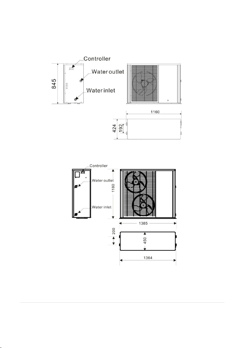
Dimensions and Scale
ESP HT 9KW
ESP HT 12KW/15KW
8 of 52| Earth Save Products-ASHP PASRW030B-D-PS
V 1.8 PASRW040B-D-PS
PASRW050B-D-PS
Page 9
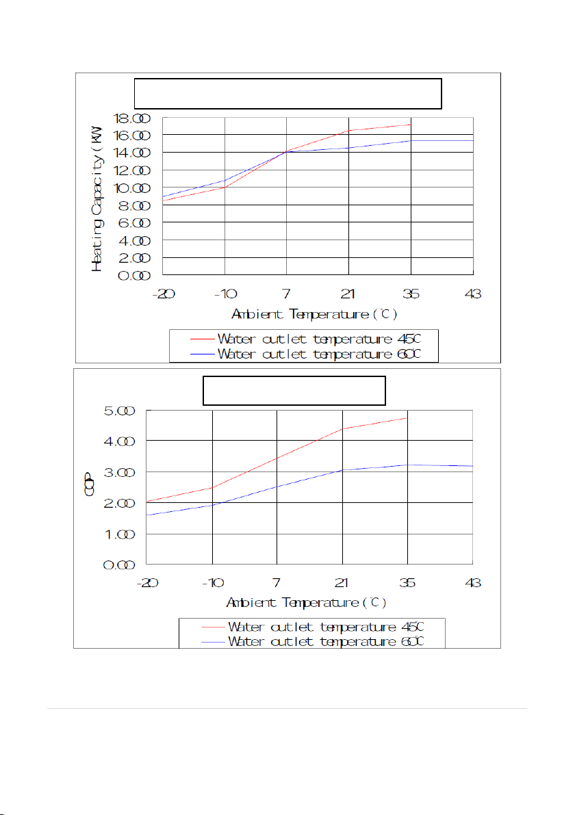
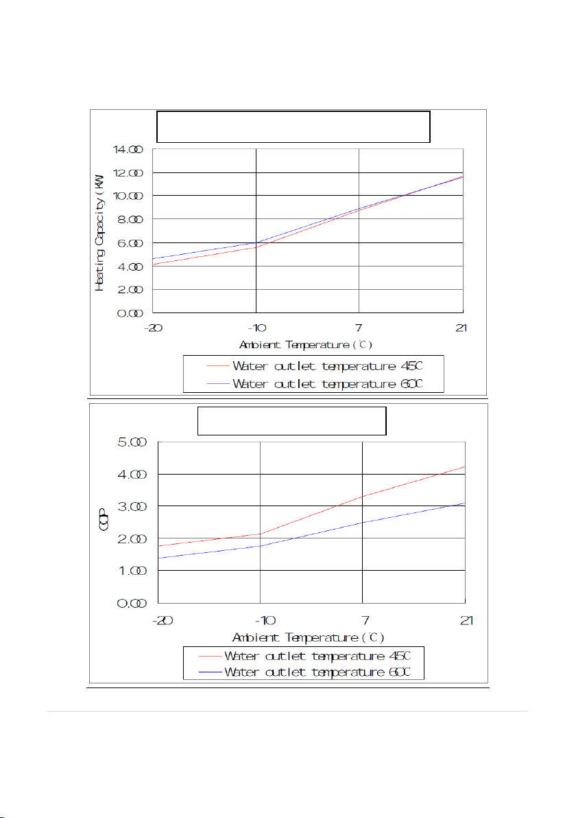
2.4 Performance Graphs
15kW HT Heat Output Curve
15Kw HT COP Curve
9 of 52| Earth Save Products-ASHP PASRW030B-D-PS
V 1.8 PASRW040B-D-PS
PASRW050B-D-PS
Page 10
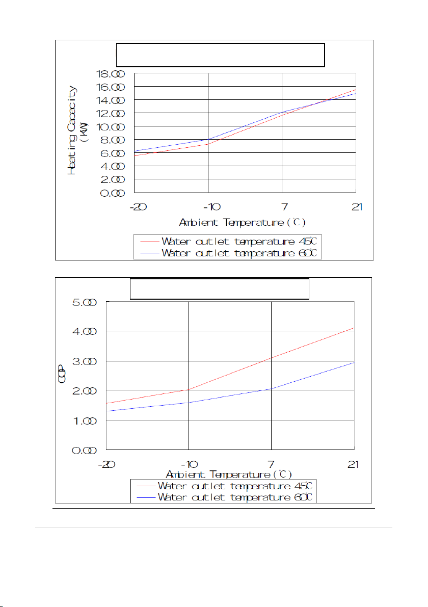
12kW HT Heat Output Curve
12kW HT COP Curve
10 of 52| Earth Save Products-ASHP PASRW030B-D-PS
V 1.8 PASRW040B-D-PS
PASRW050B-D-PS
Page 11
9 kW HT COP Curve
9kW HT Heat Output Curve
11 of 52| Earth Save Products-ASHP PASRW030B-D-PS
V 1.8 PASRW040B-D-PS
PASRW050B-D-PS
Page 12

3.0 Installation and Maintenance
Professional
installer
is required
The heat pump must be installed by a suitably qualified engineer.
Failure to ensure this can cause damage to the unit and may
cause serious injury. The unit’s warranty will also be invalidated if
a suitably qualified engineer is not engaged to install it.
Earthing
required
Please make sure that the unit and power supply are soundly
earthed.
3.1 Cautions and Warnings.
It is of the highest importance that you read and understand this manual and
that the unit is installed in accordance with it. The manual is here to help
with installation and to ensure that damage to people or property is avoided.
INCORRECT INSTALLATION WILL INVALIDATE ANY GUARANTEE.
THE UNIT MUST BE INSTALLED, COMMISSIONED AND MAINTAINED BY
A COMPETENT INSTALLER/ENGINEER IN ACCORDANCE WITH LOCAL
REGULATIONS AND BY-LAWS. FOLLOWING INSTALLATION AND
COMMISSIONING, THE OPERATION OF THE UNIT SHOULD BE
EXPLAINED TO THE END USER BY THE INSTALLER/ENGINEER AND THESE
INSTRUCTIONS LEFT WITH THEM FOR FUTURE REFERENCE.
All plumbing works and electrical works must be carried out by a suitably
qualified plumber and electrician respectively. This is mandated by English
law and there are severe penalties if works are carried out by unqualified, or
not suitably qualified, engineers and tradesmen.
IMPORTANT NOTES:
Below you will find information that is critical for the safe and proper installation
and use of the unit. Please make sure that you understand the contents as it is
written to help avoid injury to end users, installer and the unit itself.
12 of 52| Earth Save Products-ASHP PASRW030B-D-PS
V 1.8 PASRW040B-D-PS
PASRW050B-D-PS
Page 13

Refrigerant
Please give full consideration to adequate ventilation being
available in the event of a refrigerant leak- this unit must be
installed outdoors.
Installation
Site
Do not install the unit near to a gas installation.
Anchor the
Unit
Make sure that the unit is secured a base that is capable of taking
the weight of the unit.
Circuit
Breaker
Make sure that the unit is connected to the power supply via a
suitably sized type C MCB.
Unit Upright
The unit must be installed level across the whole width. See
section 3.4 for further details.
Do NOT
Do not push anything through the grills protecting the unit, or into
the fan blades when they are running and make sure that children
cannot access the unit or play close to the unit.
Shut off the
power supply
If there is an unusual sound or smell coming from the unit,
immediately shut off the power supply and call your installation
engineer.
Suitably
qualified
engineer
The unit should only be moved and/or repaired by a suitably
qualified engineer.
Do NOT
Do NOT try to install, move or repair the unit yourself – it is NOT
worthwhile running the risk of injury.
Transporting
the Unit
The unit must be transported in the vertical position.
Where to site
the unit
The unit must only be installed outdoors – the unit is not
designed, nor suitable for, installation ANYWHERE inside the
house. The Unit needs to be sited where it can receive and expel
large volumes of ambient air and condensate from the unit must
be drained away to a suitable point to avoid water running from
the unit on to walkways where ice may form. If the unit is to be
left unused for any significant period of time, it should be drained
OPERATING NOTES:
MOVE AND REPAIR NOTES:
OPERATION NOTES:
13 of 52| Earth Save Products-ASHP PASRW030B-D-PS
V 1.8 PASRW040B-D-PS
PASRW050B-D-PS
Page 14

down. Make sure that the flow and return pipework from/to the
unit have a full flow level valve fitted in-line so that the unit may be
isolated from the complete system before draining it down – this
avoids the waste of glycol if the whole system were to be drained
down. Make sure that pipework outside is properly lagged so that
it will not freeze in cold weather when the unit is not in use.
Shut off the
power
When cleaning or working on the unit, shut off the power supply.
You MUST
You must use a suitable power supply that is appropriately fused.
IMPORTANT SAFETY INFORMATION FOR THE END USER
− Installation of the heat pump must only be carried out by persons with
suitable engineering qualifications and experience.
− Do not attempt to modify, repair or service the heat pump yourself,
unless you have been appropriately trained and are suitably
qualified.
− Do not insert body parts or any other items into the air inlet or air outlet;
the fans are provided with a guard for good reason!
− Save in emergencies, do not start or stop the unit by switching the power to
the unit on or off; always use the controls provided on the unit/controller.
Starting/stopping the heat pump using mains power is dangerous for you and
may damage the unit.
− Ensure that the heat pump is protected from prolonged exposure to
large quantities of water (e.g. leaking gutters). Failure to do so may
damage the unit.
− Do not operate the unit or the programmer with wet hands/fingers.
− Upon replacement of any fuse in any part of the power feed to the unit,
ensure a correct replacement is used. Do not, under any circumstances,
use a fuse that is too large or bridge the fuse with silver paper, nails,
wire, or anything similar.
− Keep the programmer for the unit out of reach of children.
14 of 52| Earth Save Products-ASHP PASRW030B-D-PS
V 1.8 PASRW040B-D-PS
PASRW050B-D-PS
Page 15

− The electrical supply must be isolated during a heightened risk of lightning
strikes.
− Do not attempt to move the appliance once installed; this must be carried
out by a qualified engineer.
− Isolate the electrical supply to the appliance if you detect an odor from
the unit, or scorching is detected anywhere in or on the unit.
− Only use the unit for the purpose intended and in accordance with this
manual.
− Ensure the area around the unit is clean, well-ventilated and kept free of all
obstructions.
− Do not keep items on top of the unit or use it to support other appliances.
− Do not under any circumstances stand on the unit - it is dangerous for you
and will damage the unit.
− Isolate the electrical supply to the unit if it is to be switched off for a period
of more than a week.
− Drain the water from the water circuit if power to the unit is to be switched
off during very cold weather.
− Periodically check the condition of any supports or wall brackets for
deterioration - have these replaced immediately if any deterioration is
evident.
− Do not wash the unit with water, alcohol, benzene, thinners, glass cleaner,
polish or powders.
− Before cleaning, isolate the electrical supply to the unit. If cleaning of any
internal part of the unit is required, this should only be done by an
appropriately qualified engineer.
- If you have any questions about the operation and maintenance of the
unit that are not addressed in this manual, or if you feel that
something in the manual is unclear, please call the seller, distributor or
ESP.
15 of 52| Earth Save Products-ASHP PASRW030B-D-PS
V 1.8 PASRW040B-D-PS
PASRW050B-D-PS
Page 16
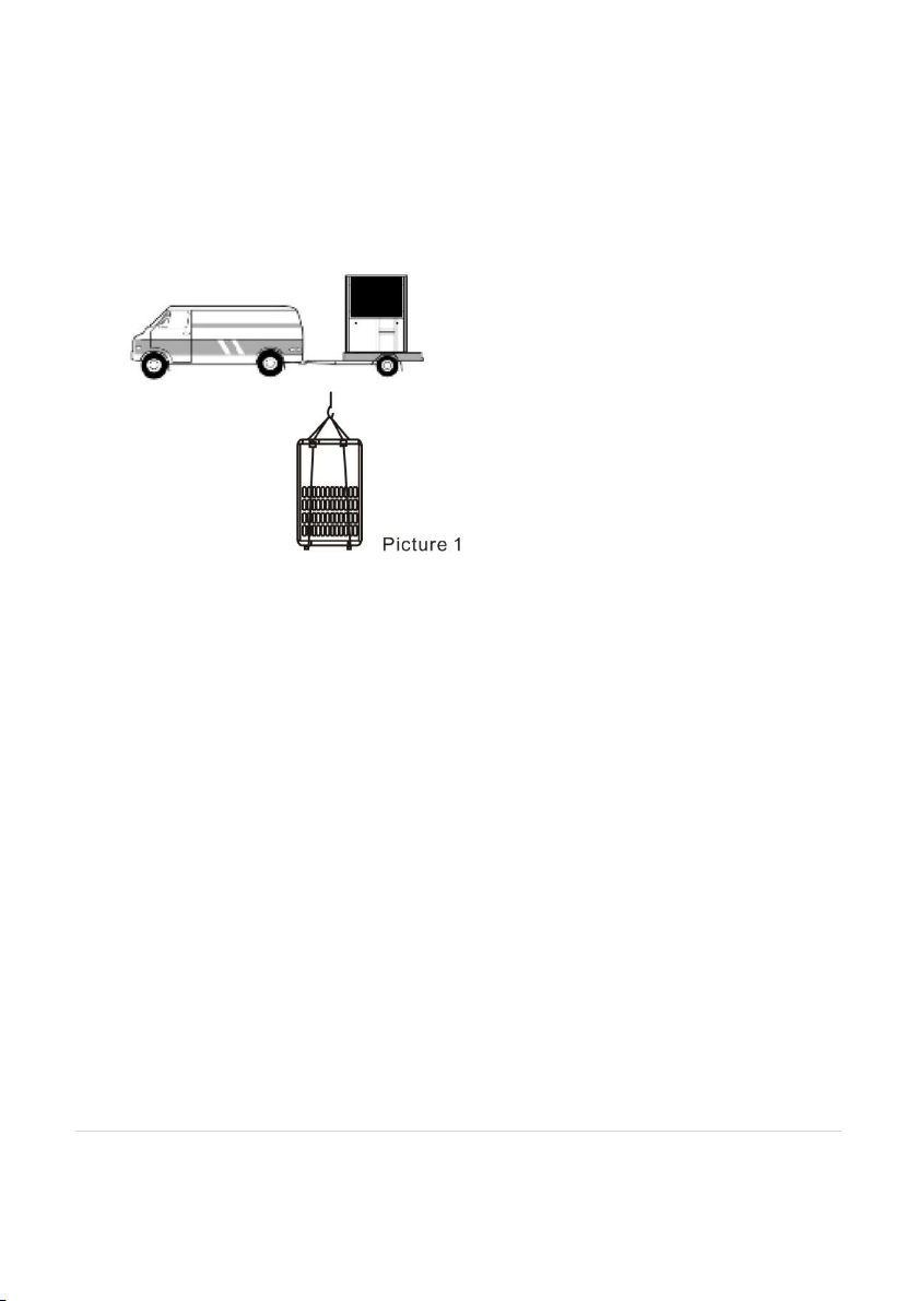
3.2 Transit
The unit must be kept upright during transit and securely fastened so that it
does not rock, slide or fall over.
Ensure suitable lifting equipment is available to move the unit around the site
and into position, whilst maintaining a vertical position. Using unsuitable
lifting gear or equipment to move the unit around can cause significant
damage to the unit externally and internally.
When using lifting gear, an 8m cable is needed and the cable should not
touch the surface of the unit – use soft packing between the lifting gear and
the unit to prevent damage to the unit.
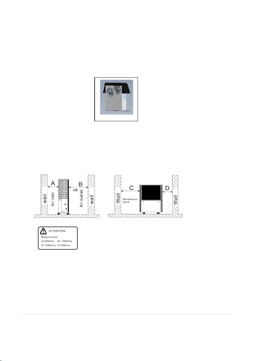
3.3 Installation Position
Please note the following important points:
The unit can be installed in any outside location that can support
heavy machinery i.e. balcony, roof terrace or on the ground.
If possible, the unit should be sited on a south facing wall to maximise
solar gain.
Circulation of air around the unit must not be impeded and the
minimum recommended clearances are shown in the diagram below.
16 of 52| Earth Save Products-ASHP PASRW030B-D-PS
V 1.8 PASRW040B-D-PS
PASRW050B-D-PS
Page 17
However, PLEASE NOTE that the unit should be positioned away from
strong winds blowing directly on to/through the unit as this can also
impair unit performance.
The unit must be kept a good distance from other heat sources and
any fuel storage.
A cover is needed in the winter to protect the unit from heavy
snowfall.
The unit should be positioned so that it is easily accessible for
maintenance and servicing.
The unit needs to be sited near a water drainage facility to allow the
safe drainage of condensing water that is produced during normal
unit operation.
3.4 Securing the Unit
The unit must be placed upon a level and firm base that is suitable to carry
the weight of the unit e.g. a 100mm concrete base. The base must provide
for the unit to be sitting at least 150mm above the surrounding ground. Allow
for a slight tilt of the unit (3mm across the width running from right to left as
17 of 52| Earth Save Products-ASHP PASRW030B-D-PS
V 1.8 PASRW040B-D-PS
PASRW050B-D-PS
Page 18

you face the fan(s)) to allow rain water run-off and any water entering the
unit to drain through the holes in the bottom of the unit.
The unit must be secured to its base using suitable fixings through the unit
feet. The rubber feet supplied with the unit must be used. Alternatively,
there are proprietary unit fixings available that include an adjustable steel
frame and legs with rubber mounting pads. Please consult ESP if you have
any questions on the use of such fixing methods; failure to comply with these
instructions will mean that the unit will not meet certification requirements.
The unit must be fixed, stable and kept vertical during operation.
3.5 Water Loop Connection
Please pay special attention to the following points when installing the unit:
I. Keep pipework as free from bends as possible to keep back pressure
in the system to a minimum. Make sure that fittings, manifolds, water pumps
and valves in the system are designed for full flow as restrictions in the
system from these can materially and adversely impact upon the
performance of the unit and effectiveness of the overall heating system.
II. The piping must be clear and free from debris. Leak testing the heat
distribution system must be carried out before connecting the unit to the
system and repairs made where required.
III. Pressure testing of the distribution and emitter system must be done
BEFORE the unit is connected to the system. If the unit is connected while
pressure testing is carried out, it will damage the unit.
IV. An expansion vessel must be installed where the heating system is
unvented/pressurised. If installing the unit in an unpressurised system, feed
and expansion tanks must be provided and they should be positioned at least
0.5 metre higher than the highest point in the heat distribution system.
18 of 52| Earth Save Products-ASHP PASRW030B-D-PS
V 1.8 PASRW040B-D-PS
PASRW050B-D-PS
Page 19

V. The unit is fitted with a water flow switch that will pause the unit
operation if water flow is not continuous (this includes where there is air in
the system). The flow switch is there to protect the unit and the setting
should not be altered. You should check that the switch is working
properly before running the unit for any sustained period. If the flow of
water is insufficient, an error code of “Flow Level” will be displayed on the
controller.
VI. The final connection to the heat pump flow and return must be made
with suitable flexible pipes to prevent vibration in to the system pipework.
Please ensure that two wrenches are employed to take up the torque created
in tightening the fittings to avoid damage to both fittings and heat pump.
VII. These flexible hoses are available from ESP as part of an Installation
Pack or individually.
VIII. Make sure that you fit automatic air vents at high points in the
system. The unit will shut down if air is in the system because the water
flow switch will recognise air in the system as no water flow and a system
alarm/protection code will appear on the unit controller. The Error Message
“Flow Level” will appear on the controller display.
IX. You must fit a pressure gauge and suitable blow off valve at the unit
inlet/outlet where it can be seen from the unit.
X. The unit is supplied with a bung below the flow/return pipes. This
bung must be removed and replaced with a drain-off- cock (DOC). There
must also be a DOC at any lower point in the system, to allow for effective
drain-down of the system as and when required. Please note that, if the
system is to be left idle for a long period in winter, the system should be
drained down. You should fit full flow lever valves on the flow and return to
19 of 52| Earth Save Products-ASHP PASRW030B-D-PS
V 1.8 PASRW040B-D-PS
PASRW050B-D-PS
Page 20
the unit so that the unit can be quickly and effectively drained down where
required for maintenance.
XI. You must fit a Y-strainer on in-line on the return pipe to the unit. This
is normally fitted in an external location and must have a full flow lever valve
side either side of the strainer to minimise glycol loss during maintenance.
Due to the mix of metals on many systems it is both advisable and preferable
to install a Spirotrap Magnabooster 2 ® rather than the minimum standard Y
strainer. Failure to fit a good quality strainer in the return flow to the unit will
invalidate the warranty on the unit.
XII. Where standard steel radiators are to be fitted, careful consideration
should be given before fitting Thermostatic Radiator Valves (TRVs) because
they are not designed to be used with low temperature systems. If the
decision is taken to use TRVs, one must not be fitted in the same room as a
room thermostat.
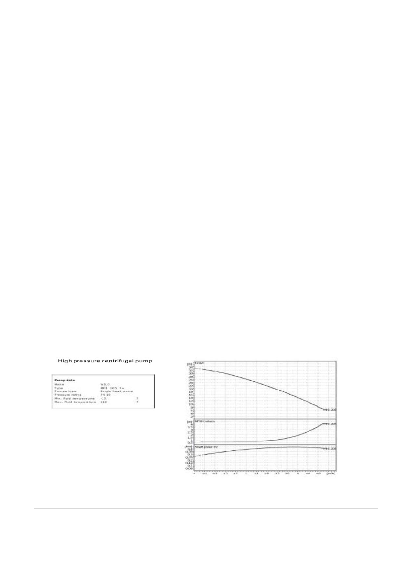
3.6 Water Pump
If using a buffer tank in the system, you will need to fit a suitably sized water
pump on the water distribution side of the system. This water pump will
need to be wired to receive an appropriate signal from the heating system.
The ASHP-fitted water pump performance parameters are as follows:
20 of 52| Earth Save Products-ASHP PASRW030B-D-PS
V 1.8 PASRW040B-D-PS
PASRW050B-D-PS
Page 21

3.7 Power Supply Connections
9 kW HT
40amp
12 kW HT
40amp
15kW HT
50amp
Before starting to wire in the power supply to the unit, please check that the
power supply is suitable for the unit (e.g. single or three phase, correct size
cable, MCB etc. is available) having taken into account the requirements of
the entire site.
The unit power specification is stated on a label on the side of the unit.
We recommend the use of a dedicated Type C MCB of appropriate rating (See
below) for connection of the power supply via the consumer unit.
Important:
All electrical work MUST be carried out by a suitably qualified electrician.
The heat pump MUST be installed with an isolation switch adjacent to the
unit and suitably positioned for general and emergency use. The isolation
switch must be suitable for the unit electrical duty and comply with
applicable Regulations.
The connection to the electrical consumer unit in the property must comply
with current electrical standards and Regulations and be done via a fused
supply/breaker that corresponds to the unit electrical capacity. Failure to do
this correctly can result in fire and/or permanent damage to the unit. If the
unit is not appropriately wired in to a suitable supply, the warranty on the
unit will be voided.
IMPORTANT! We know that suitably qualified electricians charge
professional level fees for work that they carry out, but it is better to pay a
professional/fully qualified electrician to connect your unit in to an
21 of 52| Earth Save Products-ASHP PASRW030B-D-PS
V 1.8 PASRW040B-D-PS
PASRW050B-D-PS
Page 22

appropriate power supply in the correct way, than for you to die trying or as a
result of a fire in your property caused by inappropriate or incorrect electrical
works. Also, it is law that only qualified electricians should install, repair or
maintain electrical connections and, if you do not kill yourself installing the
unit, you run the risk of prosecution if you do not comply with the law. It is
not an exaggeration to say that, if you install/connect your unit to a power
supply and that installation/connection causes injury to, or death of someone
(even years after installation), you can be prosecuted under criminal law for
murder, manslaughter or bodily harm and spend many years in prison as a
result. IT IS NOT WORTHWHILE RUNNING THIS RISK.
SO, GET YOUR UNIT WIRED IN BY A PROFESSIONALLY QUALIFIED
ELECTRICIAN IF YOU DO NOT KNOW SOMEBODY THAT IS QUALIFIED TO DO
THE WORK, FIND SOMEONE AND DO NOT BREAK THE LAW BY DOING THE
WORK YOURSELF.
The unit must be connected to the power supply through a two port rotary
isolation switch, fixed in close proximity to the unit and as required by
relevant Regulations.
The following points should be noted in relation to power supply wiring and
system components:
Open the front and side panels to access the power supply terminal.
The power supply must go through the protective wire accesses and
be connected to the terminals in the control box.
Connect the 3 core signal wire plugs into the main controller
terminals.
If an additional water pump is being used (e.g. on the heating system
side of a buffer tank) the additional water pump will need to be
connected to the same power supply as the water pump located
inside the unit so that they operate at the same time.
In the Appendices to this manual you will find wiring diagrams for the units.
Please use these diagrams when introducing power or other wiring into the
22 of 52| Earth Save Products-ASHP PASRW030B-D-PS
V 1.8 PASRW040B-D-PS
PASRW050B-D-PS
Page 23

unit. You should also use these diagrams to check the installation through
before starting it up.
3.8 Power Cable and Switch
The unit must have its own independent power supply from the
consumer board. This power supply must be equipped with a
suitable ampere rated MCB.
The power supply must be equipped with a two port rotary isolation
switch that has at least a 3mm contact separation at all poles.
The wiring must be completed by a suitably qualified and accredited
electrician
All wiring should be routed neatly, be kept as far away as possible
from the units water pipes and valves and comply with relevant
Regulations. High voltage and low voltage wiring should be clearly
separated.
Part L2 of The Building Regulations requires that the heating system
be fitted with a 7 day programmer. However, the most efficient way
of running an ASHP system is to program is to ALWAYS On. An L2
compliant programmer may be used but it is very IMPORTANT that
any signal going back to the heat pump from the heating system
thermostat and/or programmer must be VOLT FREE ! The heating
system thermostat/ programmer controller is wired to terminals
25&26 inside the heat pump (these connections are not polarized) –
see appendices. If you do not use a volt free programmer you WILL
damage the ASHP unit.
3.9 Normal Heating Water Flow Temperatures
The heat pump should be installed with a buffer tank of suitable size (consult
your supplier). The buffer tank will store water at a constant temperature
and the stored water may be used for heating or cooling. Typically, for under
floor heating the water flow temperature should be 35 °C, for Thermovec (fan
coil) units 45-50 °C and for radiators 35-50 °C. For under floor heating, you
must consider and take account of the floor finish/covering to be used as this
23 of 52| Earth Save Products-ASHP PASRW030B-D-PS
V 1.8 PASRW040B-D-PS
PASRW050B-D-PS
Page 24

may impact upon the performance of the system and the transfer of heat in
to the area to be heated. Guidance on emitter systems can be found at
www.microgenerationcertification.org/admin/documents/MIS%203005%20S
upplementary%20Information%202%20%20Heat%20Emitter%20Guide%20v2.0.pdf where guidance can be found on
pipe spacing for under floor heating and sizing fan coil units (such s the ESP
Thermovec unit) and wet radiators. It should be noted that TRVs
(Thermostatic Radiator Valves) are not designed for use with low temperature
systems and, if the decision is taken to use them, one should not be fitted in
any room where a room thermostat is fitted.
Simple heating and hot water system configuration:
Since the heat pump can comfortably heat the system water to 60 deg C, it is
capable of supplying hot water by way of a suitable hot water cylinder (to
taps, showers, etc). However, ESP strongly recommends that the Space
Heating and Domestic Hot Water (DHW) systems are kept separate; the space
heating to be provided by an ASHP and the DHW to be provided by an
Ecocent to achieve maximum efficiency and economy.
Because water composition can vary greatly, it is not ESP’s policy to issue
recommendations relating to water treatment. The user or the owner is
responsible for contacting a specialised water treatment company to obtain
water treatment advice appropriate to your location. Appropriate water
treatment processes/devices must be fitted to ensure the longevity of the
unit and its proper operation.
The unit system must have a water glycol mix in it to protect the unit/system
in cold weather - the mix is stated on the label on the side of the unit. Units
in certain colder locations may need more glycol in the mix and you should
consult your installation engineer or ESP to ensure that you use an
appropriate mix. WARNING!! - GLYCOL CAN BE POISONOUS - PLEASE BE SURE
TO USE A NON-TOXIC BRAND AS VERY LITTLE GLYCOL NEEDS TO BE
INGESTED TO BE FATAL. ESP/YOUR INSTALLATION ENGINEER CAN SUPPLY
NON-TOXIC GLYCOL UPON REQUEST.
24 of 52| Earth Save Products-ASHP PASRW030B-D-PS
V 1.8 PASRW040B-D-PS
PASRW050B-D-PS
Page 25

3.10 Unit Commissioning Checks
Please carry out the checks noted below before commissioning and starting
up the unit. These checks are not exhaustive & should be used a startingpoint; your installer will use experience and Best Practice when
commissioning the unit:
Make sure that the fan(s) rotate freely.
Check the buffer tank, manifolds, under floor heating system,
radiators, fan coils (as appropriate) and make sure that the pipe work
is securely connected and the relevant valves are open and that there
are no leaks. Also, make sure that fittings that have operating flow
directions are, indeed, fitted so that the water flows in the right
direction.
Check that there is adequate water in the system and that it is clean.
Make sure that you have vented all air from the system – air in the
system will cause the unit to shut down shortly after starting up as air
passing the flow switch in the unit will be recognised by the flow
switch as a flow problem.
Check that the system is pressurised to the correct level (0.2MPa).
Check the wiring to make sure that the system wiring conforms to the
diagrams and Regulations and that it is properly and securely
earthed. Also, make sure that electrical connections are tight.
Visually inspect the heat pump to make sure there are no loose parts.
When the power is first turned on to the unit, immediately inspect
the controller to make sure there are no error messages or warnings
showing. Because it can be difficult to purge a system of air
immediately, it is not uncommon to see an error message of “FL”
(meaning Flow Level) on the controller display indicating residual air
in the system.
25 of 52| Earth Save Products-ASHP PASRW030B-D-PS
V 1.8 PASRW040B-D-PS
PASRW050B-D-PS
Page 26

Once you have turned on the heat pump, check the water pressure
gauge and it should be running at 0.2 MPa when the water pump is
running.
After the water pump has been running for approx. 1 minute, the
compressor will start. When the compressor starts up, listen carefully
for any strange or abnormal noises coming from the unit. If you hear
anything that is unusual, switch off the unit immediately and consult
your supplier.
Check whether the power input and running current is in line with the
information in this manual.
When using under floor heating, adjust the actuators on the water
loops to make sure that the water supply to each valve is operating
and that the water is heating and cooling, as required.
Once the system has reached its required running temperature, check
that the output temperature is stable.
PLEASE NOTE – Control settings are factory set for UK conditions and will NOT
need alteration– PLEASE DO NOT TRY TO CHANGE THE CONTROL SETTINGS. If
you are having control issues, check with the unit supplier or ESP.
Upon completion of commissioning and when the unit is running correctly in
a steady state, the installation engineer must complete an Installation and
Commissioning certificate in the template found in Appendix 3.
3.11 General Maintenance
Whilst no formal maintenance is required, you should note the following:
Monitor the air and water supply frequently to ensure it is clean –
check and clean the in-line water filter periodically.
Please note that the unit, when left idle, will automatically start up
every 72 hours to carry out a short maintenance cycle to prevent the
water pump sticking.
Clean the evaporator to the rear of the unit as and when required –
this will depend upon the site of the unit and may need cleaning as
26 of 52| Earth Save Products-ASHP PASRW030B-D-PS
V 1.8 PASRW040B-D-PS
PASRW050B-D-PS
Page 27

often as once per month. Maintaining the evaporator will keep heat
exchanging efficiently and will save you money. Do not power-wash
the evaporator.
Make regular checks of the system pressure. If the pressure drops
significantly make sure the fault is diagnosed quickly and repaired
accordingly – it is possible that the system has a leak and this must be
found and repaired.
If the pump is to be unused for any protracted period, it is important
to drain down the unit. When fitting the unit, install a full flow lever
valve on both the flow and return pipes so that the unit may be
isolated from the rest of the system and drained down easily, without
losing all water and glycol from the system. A water recharge and
inspection will be necessary before restarting the unit.
The unit and the water distribution system must be protected in the
winter to avoid freezing – this means using glycol in the system and
ensuring that water pipes are properly lagged with waterproof high
grade lagging with a wall thickness of at least 30mm. See further
notes below - these points must be observed to avoid the warranty
being invalidated:
a. Do not shut of the power supply to the heat pump in the
winter, when the air temperature is below 0°C. If the inlet water
temperature is above 2°C and below 4°C, the water pump will
automatically start to prevent the system from freezing. If the inlet
water temperature is below 2°C the system will automatically heat
the water to 2°C+.
b. Use anti-freeze (Glycol water) Follow the guidelines below to
ensure you have the correct amount of anti-freeze in system:
27 of 52| Earth Save Products-ASHP PASRW030B-D-PS
V 1.8 PASRW040B-D-PS
PASRW050B-D-PS
Page 28
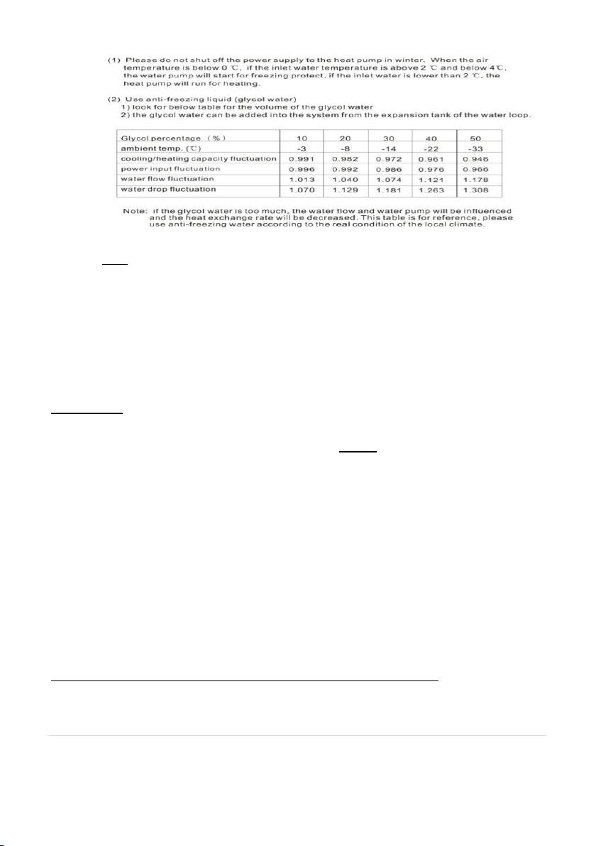
Note: Too high a concentration of the anti-freeze will affect the performance of the
heat pump.
PLEASE NOTE – ESP CAN PROVIDE AN ANNUAL INSPECTION/MAINTENANCE
PACKAGE, IF REQUIRED.
3.12 Operating notes for the end user
WARNING!
Before doing any work on the heat pump you MUST switch off power to the
unit at the twin port isolator switch (that should be installed next to the unit).
Servicing and maintenance of the unit must only be carried out by qualified
technicians. ESP can provide a full inspection and maintenance service, if
required.
Repeated triggering of safety and control devices must be thoroughly
investigated and any fault causing the triggering corrected before further use
of the unit. Please call your service engineer/installer should safety or control
devices be triggered.
You should carry out some basic checks on your unit regularly to maintain it in
optimum working order - these consist of standard checks (look at the
operating temperature settings, checking water flow and temperatures, see if
28 of 52| Earth Save Products-ASHP PASRW030B-D-PS
V 1.8 PASRW040B-D-PS
PASRW050B-D-PS
Page 29

there is scorching visible on the unit, make sure that the unit surroundings are
free from debris and growth of foliage from plants) and should be carried out
every 3 months and after the unit has been out of service for any prolonged
periods.
The inline filter/strainer should be cleaned regularly for the first six months
and at least once a year there after. It is recommended that you use a high
performance filter/strainer such as the Spirotech Magna-booster 2 ® rather
than a basic “Y” strainer/filter. Please discuss this with your installer.
WARNING!
The grills on the unit are intended to protect installation engineers from injury
from the evaporator during handling and installation work.
However, the grills located over the evaporator can create a risk of clogging
with a frost or ice during very cold weather. You may remove the grills over
the evaporator during periods of very cold weather but, if you do this, you
must make sure that the evaporator is not damaged while the grills are
removed and it is therefore advisable to keep people and pets away from the
unit. Please also note that the metal "fins" on the evaporator are sharp and
you should not touch them and also prevent others touching them - they can
cause serious cuts. The fins are also fragile and you should avoid bending
them.
If in any doubt about what to do, please call your installation engineer or ESP.
WARNING!
Very important:
The 3 phase model has built-in set phase protection. If the phase
sequence is wrong or there is a phase is missing, the controller will
29 of 52| Earth Save Products-ASHP PASRW030B-D-PS
V 1.8 PASRW040B-D-PS
PASRW050B-D-PS
Page 30

prevent the unit from starting up. Once the fault has been corrected,
the unit will start.
Delivery:
The ESP range of high temperature ASHP units can provide domestic hot
water and space heating by extracting heat energy from the surrounding air
and transferring it in to the system water.
Please note, any ESP ASHP is fully checked before delivery to make sure
that it is operating as it should. Any visible damage should be reported to
your supplier immediately and noted on any delivery note – if you are able
to photograph damage, please do so. The delivery driver should be
informed and any damage shown to him. Make sure that the delivery
driver notes your concerns on the delivery record.
The ESP Classic range of ASHP's is designed and built to give years of
trouble-free service and the content of this manual is important to
ensuring the maximum life span is achieved and performance delivered
with the least difficulty and cost.
If you are seeking any Government support for the cost of purchase,
installation and/or operating the ASHP, please ensure that you understand
fully what is required to enable you to access that support. ESP accepts no
responsibility or liability for any failure to obtain the support that you may
be seeking and complying with any rules or requirements to obtain any such
support is solely your responsibility.
30 of 52| Earth Save Products-ASHP PASRW030B-D-PS
V 1.8 PASRW040B-D-PS
PASRW050B-D-PS
Page 31

Some Important Additional Information:
FROST PROTECTION
As the ASHP will be fi tted exte rnally to the property being heated, the
water in the system could freeze up, if not protected. The unit should have
glycol mixed with the system water to prevent freezing and the required
mix of glycol/ water is stated on the label on the unit. Failure to use the
correct mix for the environment will invalidate the warranty.
DEFROST MODE
If the temperature is cold enough for ice to develop on the evaporator at the
rear of the unit and the unit has failed to reach the target system
temperature within the pre-set period of time, the unit will automatically
enter defrost mode. This will divert heat from the heating circuit back to the
evaporator until the ice has melted. The DEFROST symbol will appear above
the temperature display and will flash during the defrost operation. When
defrosting, the unit can give off a lot of steam and this is normal.
SERVICING
While it is not necessary to carry out an annual service on the appliance
like that for a gas/oil boiler, regular inspections are advisable. Remove
leaves, debris, moss, etc. from the evaporator at the rear of the unit. Also,
certain Government grant/support Schemes require that, for grant/support
funding to be payable, the unit be inspected and that inspection recorded in
a unit i ns p e ct io n lo g . It is YOUR responsibility to ensure that the rules
of any such Scheme are complied with. ESP offers a planned inspection
service and, if required, you should enquire about this by calling us.
31 of 52| Earth Save Products-ASHP PASRW030B-D-PS
V 1.8 PASRW040B-D-PS
PASRW050B-D-PS
Page 32

COIL TEMPERATURE CUT OUT
Should the coil reach too high a temperature, the unit will automatically
switch off until the temperature has reduced sufficiently. Please note that
the unit may take several minutes to restart. This is normal.
COMPRESSOR OUTLET TEMPERATURE CUT-OUT
Should the compressor outlet reach too high a temperature, the unit will
automatically switch off until the temperature has reduced. Please note that
the unit may take several minutes to restart.
GOING ON HOLIDAY?
If power to the heat pump is to be shut down for a long period during very
cold weather (and when the glycol in the system water will not offer
adequate protection – NOTE - the system must have glycol in it to the
required mix), it is advisable to completely drain the system. However,
frequent draining of the system should be avoided, especially in hard water
areas, as this can lead to the build-up of scale in the heating circuit. To avoid
draining down the whole system, the flow and return pipework (to and from
the unit) should have full flow lever valves fitted on each port so that
minimum drain-down is needed to protect the unit. However, you should
also have regard to protecting the pipework leading up to the unit and in the
house. Suitable waterproof lagging and/or other protection should be
installed.
FAILURE TO START UP
If the unit fails to start for no apparent reason, carry out the following checks
before making changes to running parameters on the controller or calling in a
service engineer:
The unit may be running through a process that deals with temporary out of
specification operating conditions to clear an operating parameter. In most
32 of 52| Earth Save Products-ASHP PASRW030B-D-PS
V 1.8 PASRW040B-D-PS
PASRW050B-D-PS
Page 33

cases, this will be cleared automatically within minutes. If it persists, check
the programmer display to see if there is a fault/protection message showing.
Refer to the guide in section 5 for basic fault finding and remedial actions.
2. Ensure there is a current ‘heat demand’ from the programmer (that the
programmer is in a heating period and that the inside temperature is below
the required temperature). Ensure that the programmer clock and timer
controls (and any auxiliary room stat controller/programmer fitted) have
been set in accordance with the instructions and that they are calling for
heat from the system. If the house is not calling for heat, the unit will not be
run.
3. Check for failure in the electrical supply. Please do not attempt to deal
with any electrical faults yourself - call in a suitably qualified electrician.
4. Check for a blown fuse. If the fuse has blown and the replacement also
fails, switch off the main electrical supply to the unit and contact your
service engineer.
5. Check the circuit breaker. If this has “tripped out”, reset and restart the
unit. If the circuit breaker trips for a second time soon after, switch off the
mains electrical supply to the unit and contact your service engineer.
Note: If the unit has been shut down due to a failure of the power supply,
the programmer contains a battery backup which will mai n ta in all settings
while the battery is charged. Make sure that you do not leave the system
water to freeze while the unit is switched off (you must have glycol in the
system to protect the unit from frost at all times).
If the unit is operating, but the system water temperature is not reaching the
target operating temperature:
1. Check that all isolation valves are fully open.
2. Check the water temperature setting is not lower than you think it
is set!
33 of 52| Earth Save Products-ASHP PASRW030B-D-PS
V 1.8 PASRW040B-D-PS
PASRW050B-D-PS
Page 34

3. Check that the vents on the back of the unit and the evaporator
have not become blocked, thereby impeding the air flow through the
unit.
4. Check the unit has not entered in to defrost mode (the DEFROST
symbol will appear above the temperature display and flash). Should
this occur, the heat output from the unit will be diverted to the
evaporator until any ice build up has been removed from the
evaporator. When in defrost mode the system water temperature will
fall and the lower system temperature will show on the unit
controller.
5. If you hear water “gurgling” in the unit, most of the time this will
not be a problem and is just the normal movement of refrigerant in
the unit. In exceptional circumstances, it could mean that you have
air in the water system that is likely to be cleared by the auto airbleeding vents on the system pipework. If it persists, it could indicate
that there is a leak in the water system that needs attention. Check
the system pressure to see if it has fallen. If it has, call your service
engineer/plumber.
6. If there is power to the unit and the programmer is calling for
heat, but the unit is not running, it could be that one of the safety
cut-out facilities has operated. This can take several minutes to clear
before the unit restarts.
You can also refer to the table in section 5 for more detailed fault
finding. If ever in doubt, or if you are concerned in any way, call your
service engineer/plumber and discuss the problems that you are
having. If you cannot contact your service engineer/plumber, please
call ESP for assistance.
34 of 52| Earth Save Products-ASHP PASRW030B-D-PS
V 1.8 PASRW040B-D-PS
PASRW050B-D-PS
Page 35

TIPS FOR LOWERING ENERGY USAGE
1) General unit maintenance can have a significant impact upon system
performance and service life. Ensure regular inspections are carried out over
the lifetime of the appliance. ESP offers a planned maintenance service, so
please ask us about this, if required.
2) Dirty evaporators and fans reduce airflow through the system, resulting in
decreased performance. Regular checks should be carried out to ensure that
these are kept clean – don’t forget to turn the unit off when working on it.
3) The unit should be protected from high winds as this can lead to reduced
airflow and efficiency as well as out of specification running.
4) While the unit should be protected from high winds, avoid siting in areas
where the airflow is restricted, resulting in recirculation of cold air over the
evaporator.
5) Insulate the pipe work and fittings to and from the unit to avoid unwanted
heat loss from the system. Use the highest quality waterproof insulation with
a wall thickness of at least 30 mm – it will pay for itself very quickly – poor
quality insulation will mean that you have a poor quality system performance
and that you are wasting a lot of money. For new builds, the requirements of
Part L of The Building Regulations (or better) for insulation will help ensure
that the heat load of the dwelling is kept to a minimum. For existing
buildings, insulation should be improved as much as possible to minimise the
heat load.
6) Do not power wash the evaporator!
7) Set the room stat temperatures as low as you can.
35 of 52| Earth Save Products-ASHP PASRW030B-D-PS
V 1.8 PASRW040B-D-PS
PASRW050B-D-PS
Page 36

8) Do not over fill the unit with glycol - see required water/glycol mix on the
label on the unit - using too much glycol alters the thermal properties of the
system water.
9) Ensure that the unit is properly installed! Poor quality, or inappropriate,
installation of the unit can dramatically reduce the performance, life span and
efficiency of the unit.
3.13 AFTER SALES SERVICE INFORMATION
A qualified service engineer is available to attend a breakdown or
manufacturing fault occurring while the appliance is under guarantee.
Please note, upon attendance by an Earth Save Products Ltd. (ESP) service
engineer, a charge may applied for any service/site visit where:
- The service engineer finds no fault with the unit.
- The cause of a breakdown is due to components not supplied by ESP.
- The cause of the breakdown is due to incorrectly installed parts within the
heating system.
- The unit has not been correctly installed (in accordance with this manual and
good installation practice) by a suitably qualified engineer.
- The breakdown occurs outside the guarantee period.
- The unit has not been properly maintained.
- The breakdown occurs due to use of unit not for the purpose designed.
- The breakdown occurs as a result of unauthorized third-party work on the
unit
36 of 52| Earth Save Products-ASHP PASRW030B-D-PS
V 1.8 PASRW040B-D-PS
PASRW050B-D-PS
Page 37

TECHNICAL ASSISTANCE
Technical advisors are available to discuss any problem with the unit. In many
cases the problem can be solved over the telephone, eliminating the need for
a service visit.
HOW TO REPORT A FAULT
Contact your installer/supplier, who should thoroughly check the installation
and/or all recent work before the attendance of an ESP service engineer is
requested.
If your own installer/supplier is unavailable, contact ESP. Please be aware that
a charge may be made for any visit not covered by the unit guarantee.
Before contacting ESP about a problem with the unit, it would help us if you
have the following information ready:
1) Appliance serial number, account number or invoice number.
2) Description of fault, including any operating parameter code which
may be displayed on the programmer.
3) Date of delivery/installation. Please note that the warranty starts
from the date of delivery.
4) Name of the company that installed the unit and when it was
installed.
37 of 52| Earth Save Products-ASHP PASRW030B-D-PS
V 1.8 PASRW040B-D-PS
PASRW050B-D-PS
Page 38
4.0 Controls and Operation
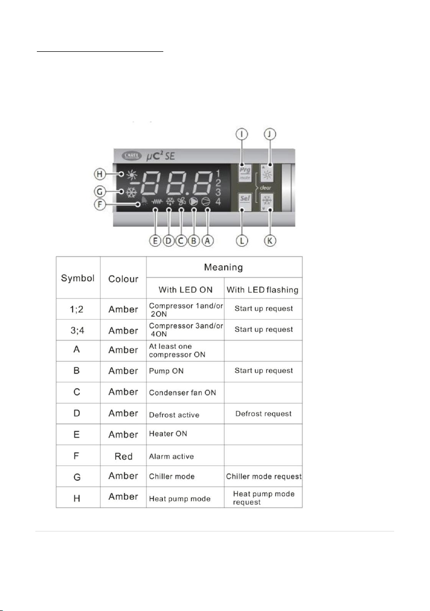
4.1 The unit controller display
Please see below a picture of the unit controller with key controls and
functions identified.
38 of 52| Earth Save Products-ASHP PASRW030B-D-PS
V 1.8 PASRW040B-D-PS
PASRW050B-D-PS
Page 39

4.2 Functions associated with the buttons
The following table gives a description of what each of the buttons on the
unit controller will do. Please familiarise yourself with them as they are
important to the operation of your unit. They are also important for the
installer:
39 of 52| Earth Save Products-ASHP PASRW030B-D-PS
V 1.8 PASRW040B-D-PS
PASRW050B-D-PS
Page 40
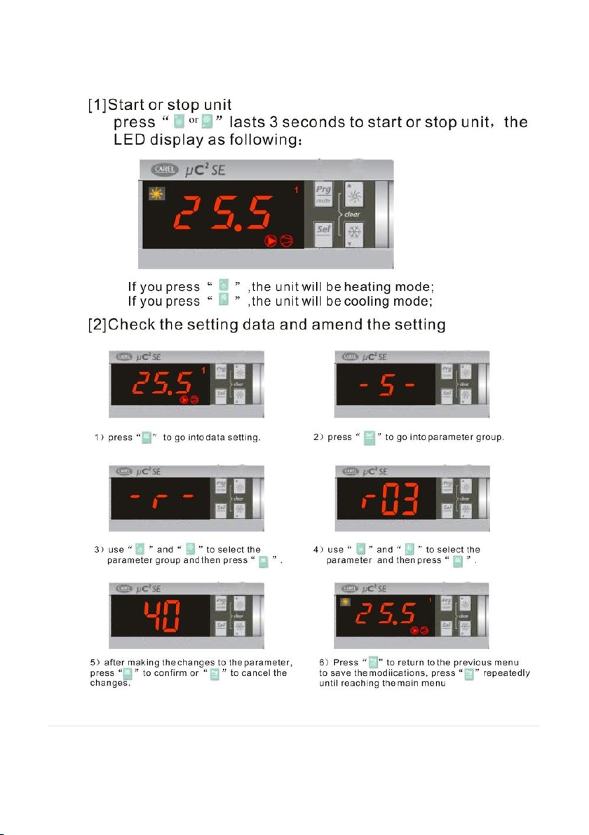
4.3 Saving Controller Parameters
(This example illustrates changing the “set point” or “flow” temperature)
40 of 52| Earth Save Products-ASHP PASRW030B-D-PS
V 1.8 PASRW040B-D-PS
PASRW050B-D-PS
Page 41

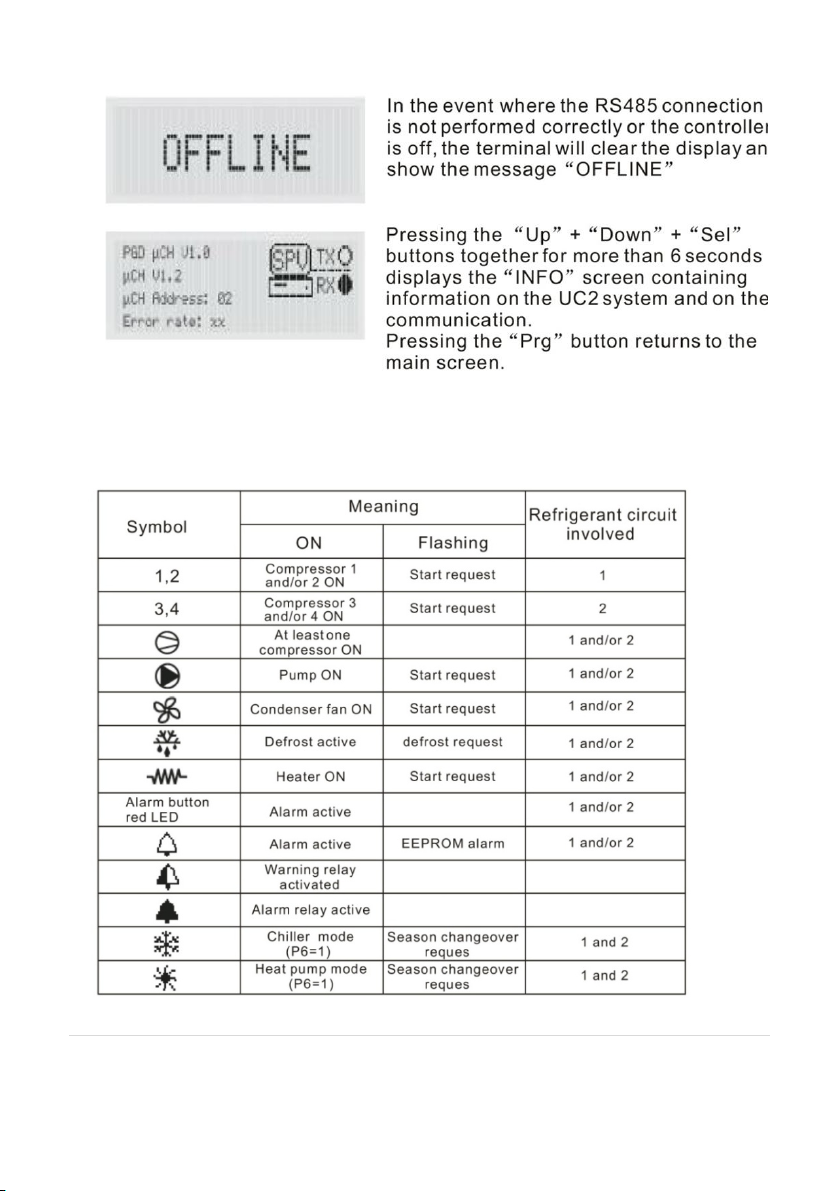
4.4 Installing a Remote Control
41 of 52| Earth Save Products-ASHP PASRW030B-D-PS
V 1.8 PASRW040B-D-PS
PASRW050B-D-PS
Page 42
4.5 Symbol Meaning
Please note below the function(s) that each of the identified symbols
performs:
42 of 52| Earth Save Products-ASHP PASRW030B-D-PS
V 1.8 PASRW040B-D-PS
PASRW050B-D-PS
Page 43

4.6 Parameters
The operating parameters are set as follows and the advice of the ESP
Technical team should be sought before changing them:
43 of 52| Earth Save Products-ASHP PASRW030B-D-PS
V 1.8 PASRW040B-D-PS
PASRW050B-D-PS
Page 44
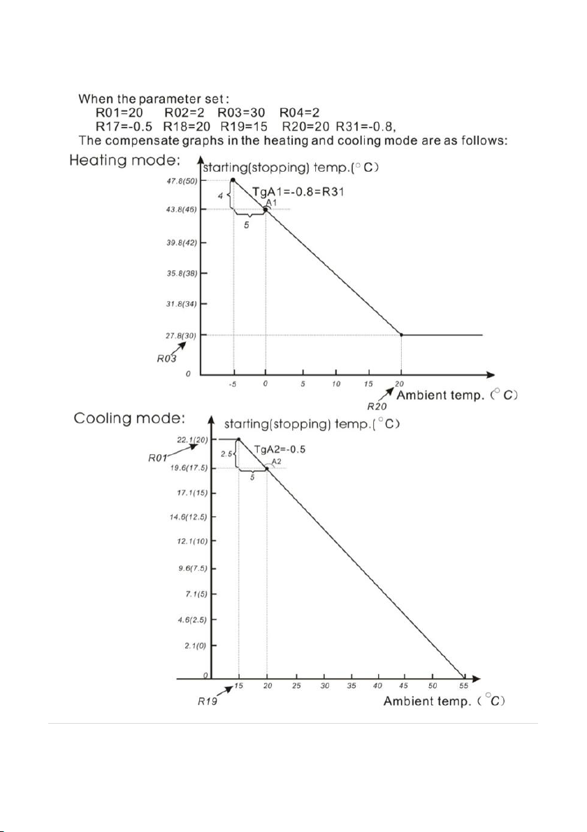
4.7 Weather Compensation Data
44 of 52| Earth Save Products-ASHP PASRW030B-D-PS
V 1.8 PASRW040B-D-PS
PASRW050B-D-PS
Page 45
45 of 52| Earth Save Products-ASHP PASRW030B-D-PS
V 1.8 PASRW040B-D-PS
PASRW050B-D-PS
Page 46
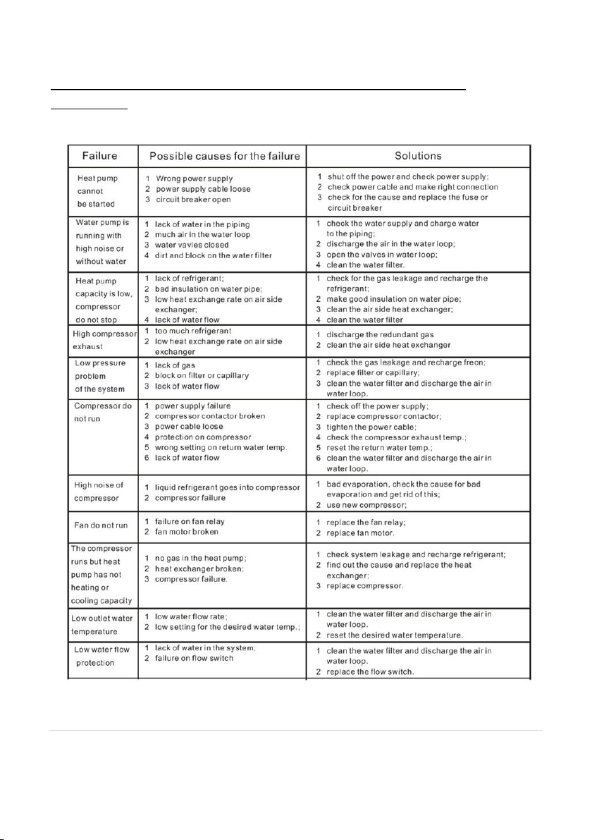
5.0 Frequently Asked Questions: Troubleshooting and Additional
Information
46 of 52| Earth Save Products-ASHP PASRW030B-D-PS
V 1.8 PASRW040B-D-PS
PASRW050B-D-PS
Page 47

5.1 Support
If you have trouble with your ESP High Temp ASHP, the ESP technical team or
your engineer will be willing to assist you.
47 of 52| Earth Save Products-ASHP PASRW030B-D-PS
V 1.8 PASRW040B-D-PS
PASRW050B-D-PS
Page 48
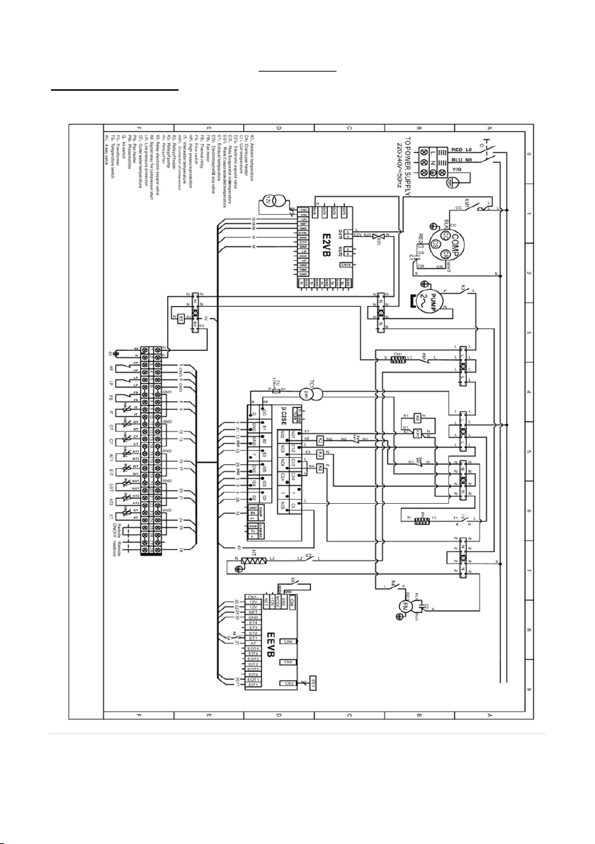
WIRING DIAGRAMS
ESP HT 9kW
APPENDIX 1
48 of 52| Earth Save Products-ASHP PASRW030B-D-PS
V 1.8 PASRW040B-D-PS
PASRW050B-D-PS
Page 49

ESP HT 12kW & 15kW
49 of 52| Earth Save Products-ASHP PASRW030B-D-PS
V 1.8 PASRW040B-D-PS
PASRW050B-D-PS
Page 50

Installation engineer's signature
Company Name (if applicable)
Company address
Company Tel No
Email address
APPENDIX 2
INSTALLATION ENGINEER’S DETAILS
50 of 52| Earth Save Products-ASHP PASRW030B-D-PS
V 1.8 PASRW040B-D-PS
PASRW050B-D-PS
Page 51

Customer Details:
Name:
Correspondence Address:
Installation Postcode:
Installer Details:
Installer Company Name:
Accreditation no. (MCS)
Address:
Postcode:
Telephone:
Emergency Telephone (if different):
Email Address:
Website:
Installation carried out by:
(if different from above)
APPENDIX 3
Installation and Commissioning Certificate
This should be completed in full and left with the customer.
51 of 52| Earth Save Products-ASHP PASRW030B-D-PS
V 1.8 PASRW040B-D-PS
PASRW050B-D-PS
Page 52

System Details
Heat Pump Manufacturer: ESP
Unit size:
Heat Pump Model and Serial no:
We have inspected the installation of the Air Source Heat Pump and can
advise that the unit has been correctly installed.
We have not inspected the system or reviewed its design.
I confirm that we are responsible for the installation, commissioning and
handover of the above Air Source Heat Pump and the same has been
carried out (so far as we are aware) in accordance with the manufacturer's
Documentation and MCS requirements
Signed: Print Name: .
Date (of commissioning): _
52 of 52| Earth Save Products-ASHP PASRW030B-D-PS
V 1.8 PASRW040B-D-PS
PASRW050B-D-PS
 Loading...