

Page 1
4/8 CHANNEL HD CCTV SYSTEM
USER MANUAL
www.espuk.com
FHDV 4 R • FHDV 8 R
FHDV 4 KB • FHDV 4 KD
FHDV 8 KB • FHDV 8 KD
Page 2

CONTENTS
DVR Description. . . . . . . . . . . . . . . . . . . . . . . . . . . . . . . . . . . . . . . . . . . . . . . . . . 3
System Connection Diagram ....................................... 4
Basic Operations ................................................. 5
Record Setup ................................................... 10
Main Menu Layout .............................................. 13
Remote Viewing ................................................ 14
Help Guide ..................................................... 15
This manual is designed to be used as a quick start guide alongside the informative general user
interface (GUI) of the DVR. The menu above is not exhaustive and is designed to lead the user
quickly to the most often required aspects of the unit.
The DVR will require a connection to a monitor to be programmed.
2
IMPORTANT NOTICE
• Please read this manual and keep for later use
• Do not use accessory devices not recommended by the manufacturer
• Please use the power adapter equipped for the unit
• Please do not touch any control parts not mentioned in the manual. Incorrect
adjustment
of a control part not mentioned in the manual may damage the machine
• Ensure air ventilation around the unit and do not cover or block the vent hole
• Do not place the unit in direct sunlight or near a heat source
Page 3
3
REAR PANEL
2
1
5
4
7
8 9
3
6
1 2
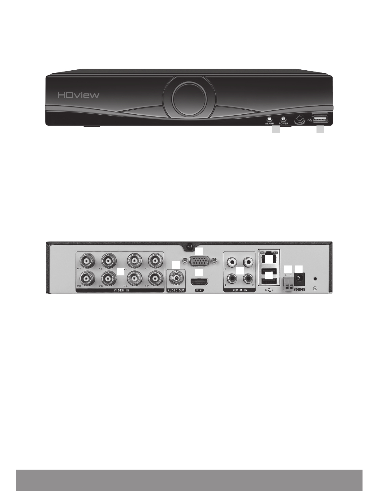
DVR DESCRIPTION
FRONT PANEL
1. System indicator lights
2. USB for mouse or USB stick
1. VIDEO IN 1-4/8 for video input from camera
2. AUDIO OUT Audio output
3. VGA Output for monitor
4. HDMI Output for monitor
5. AUDIO IN Audio input
6. LAN Socket connection for ethernet cable
7. USB 1 + 2 For mouse control, USB backup and Wifi dongle
8. RS485 + - Signal Control
9. DC12V Power input
Page 4
4
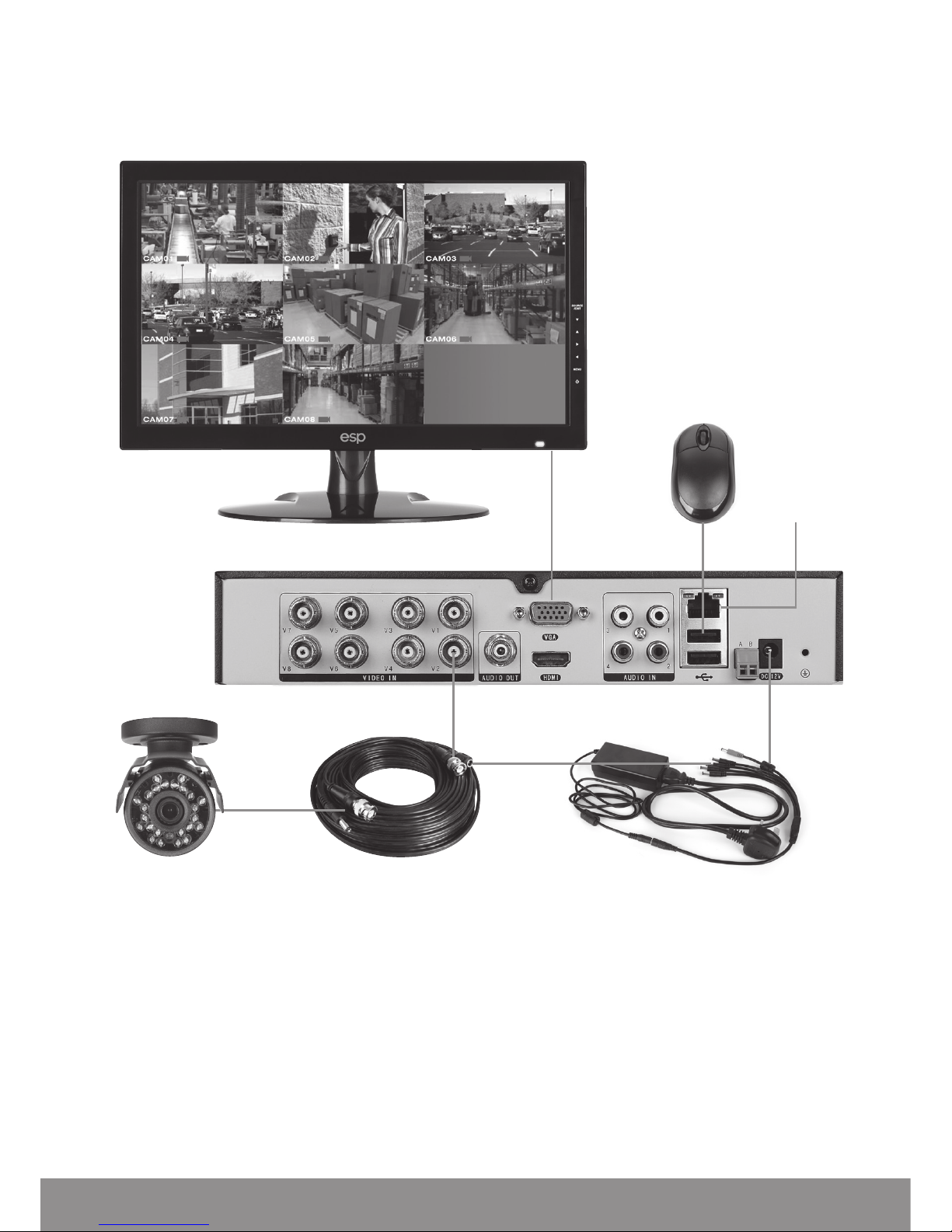
DVR CONNECTION DIAGRAM
Notes on Camera Connection:
The DVR is specifically designed for High Definition cameras using AHD technology.
The DVR can also support standard definition cameras.
Monitor
DVR rear panel
VGA / HDMI
Connection
Mouse controller
Local area
network
Power supply / Splitter lead
Video / Power cable
Video Input
(BNC female)
BNC Video (female)
Power Jack (female)
Camera
Page 5

5
BASIC OPERATIONS
CONNECTION TO A MONITOR
Use either HDMI or VGA output to connect to a monitor and select the correct input
channel on the monitor.
POWER ON
Plug one lead from the 5-way power supply into the 12VDC power supply input
marked on the DVR. Turn on the DVR at the mains power point. The Power supply
indicator light will illuminate on the DVR’s front panel followed by several short
bleeps.
POWER OFF
Select Logout from the Shortcut menu and turn off the DVR at the mains power
source.
N.B Auto resume after power failure. If the DVR is shut down abnormally, the DVR
will automatically backup video and resume previous working status after the
power is restored.
MOUSE CONTROLLER CONNECTION
In order to prevent un-authorised tampering majority of DVR functions of are
controlled via the mouse controller.
Page 6

6
START-UP WIZARD
The Set-up Wizard takes the user through basic system settings. More advance
options and settings are found in the Main Menu.
INTRODUCTION
LOG-IN
An opportunity to change the password is provided within the settings menu.
The default settings are:
User Name: admin
Password: ‘leave blank’
Page 7

7
GENERAL
Set time and date:
CLOUD
If status is ‘Connected’ use the QR codes to download the required APP and serial
number.
Page 8

8
LIVE VIEWING
On start up the DVR will display a divided screen. Using the Mouse Control, double
click on any image to bring to full screen. Double click again to return to that main
divided screen.
The recording status and alarm status are indicated by the following icons:
Recording Motion Detect
SHORTCUT MENU
Right-clicking on the live camera screen will activate the Shortcut Menu where the
most regularly used settings can be found.
Main Menu Enter to adjust system settings
Start-up Wizard Enter to adjust initial system settings
Record Playback Shortcut for Record Mode
Quick record To view recorded files
PTZ Control Settings for Pan Tilt and zoom cameras
Colour Setting Edit colour settings per channel
Output Adjust Adjust display output settings of DVR
Logout Logout, Shutdown or Reboot system
View 1 1 Channel view
View 4 4 Channel view
View 8 8 Channel view (On 8 channel version only)
Page 9

9
ACCESSING THE MAIN MENU
Right click the mouse controller anywhere on screen to activate the Shortcut Menu.
Selecting Main Menu option will automatically display the following screen;
Page 10

10
RECORD SETUP
CONTINUOUS RECORD
As factory set, the unit is programmed to record all channels continuously.
MOTION DETECTION RECORD
Right-click on the screen to bring-up the Shortcut Menu select Main Menu and log-in
• Select Record > Control
• Select Channel as ALL
• Select Record Control as Schedule
• Select Week Day as ALL
• Select Schedule 1 as MD only
• Click Save
• From the Main Menu select Alarm > Motion Detect
• Select Channel as ALL
• Select Enable
• Select Record Channel 1-4/8/16
• Click Save to finish set-up
ADDITIONAL RECORD OPTIONS
Select Main Menu > Record > Record Config.
Channel
Select 1–4/8/16/ All
Pre-Record
The system can automatically archive up to 30 seconds of recording prior to a motion or alarm
trigger event
Record Control
Selects the recording preference either by schedule, manual or stop option.
Week Day
Enables recording requirements set for each day
Schedule 1-6
Each day can be segmented into 6 specific recording periods throughout the day
NB. When entering the ‘Record > Control’ menu the default screen will always start with a
display for Channel 1 and the current day’s schedule.
Page 11

11
RECORDING PLAYBACK
Right click on the live camera view, login and select Record Playback directly from the
Shortcut Menu.
On the playback menu refer to the right hand side of the screen and enter the
following;
Standard Playback Operation;
• Main Type: Normal Play
• Select which channel is required
• Select required month
• Select required day
• Click the Play button to begin playback
Event Playback Operation;
• Main Type: Event Play
• Sub Type: Event Type
• Select which channel is required
• Enter Begin and End times
• Select search
• Double click on the event list to start playback
NB. Practice playing back footage to familiarize with the process before an incident occurs.
NB. For best performance it is recommended that only one channel at a time is selected
for playback
Page 12
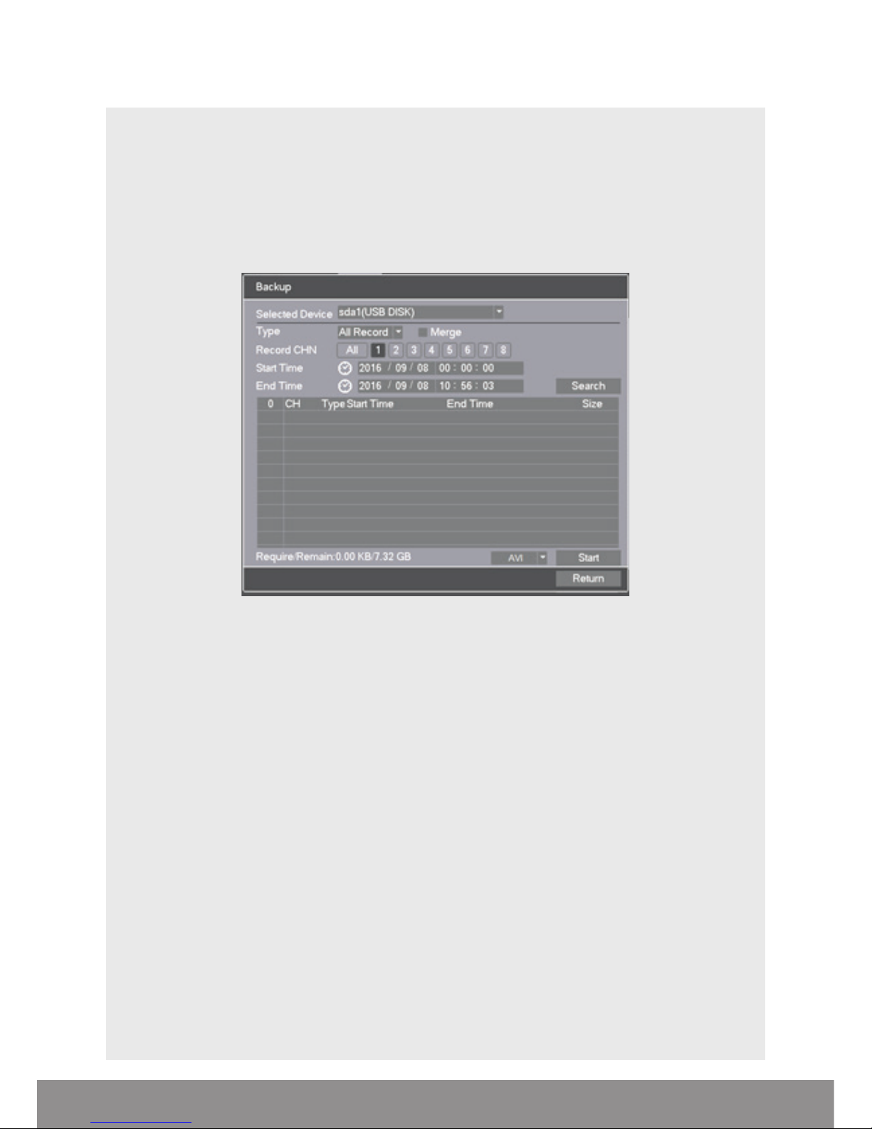
COPY RECORDING TO USB
Right click on the live camera view and select Main Menu directly from the
Shortcut Menu
• Insert USB stick into DVR
• Select Record > Backup
• The details of the USB stick will be visible, Select Backup
• Select Channel number required
• Enter Start and End time
• Select Search
• Select AVI and Select Start
• Notification will be received once complete
NB. Practice backing-up footage to familiarize yourself with the process before an
incident occurs.
NB. The AVI file will enable playback via a PC using AVI players
12
Page 13

Main Menu Sub Menu Function
Record
Control
Set the recording configuration, recording type,
recording time section
Backup
Detect or format backup equipment, back the
selective files
Alarm
Motion Detection
Set motion detect alarm channel, sensitivity,
area and linkage parameters
Video Mask
Set camera mask alarm channel, sensitivity and
linkage parameters if sys. vulnerable to tamper
Video Lost
Set camera loss alarm channel, sensitivity and
linkage parameters if sys. vulnerable to tamper
Abnormality Alerts from abnormal operation
Network
Network Set basic network parameters
Email Set email parameters
FTP Set FTP parameters
NTP Set NTP parameters
Cloud View Cloud Connection information
DDNS Set DDNS parameters
UPNP Set UPNP parameters
Access Control IP access control parameters
Setting
General Time / Date settings
Encode Set camera quality control
Display
Set channel name, icon state,
transparency, cover area and time title
Tour Set patrol mode and interval time
PTZ Set PTZ parameters
Account Set User accounts and passwords
Channel Type Manufacturer Menu ( Do not Adjust )
Maintain
Version Manufacturer Information
Configuration Import Configuration / default system settings
HDD Manage HDD Information and options
Online Users Displays current remote connections
BPS Data consumption rate by channel
Log View system Log
Shut Down Shut down options
MAIN MENU LAYOUT
13
Page 14

REMOTE VIEWING
Networking should always be carried out by a competent/qualified engineer,
specifically when adjusting settings on the router which is sometimes required for
remote viewing.
To remote view please refer to the Remote Viewing guide.
Once the DVR has been added to the network there are different methods to view
the system remotely:
Smart-phone APP: ESP HDview (IOS/Android) )
PC/Laptop Software: HDview CMS supplied on the included CD (Windows compatible)
NB. ESP are unable to guarantee that every device will be compatible with the DVR and
software supplied. Specific models of phone, tablet or other device, the hardware it contains,
the service provider, the types of data services offered and specific phone / device plan will
all affect the performance of PC / mobile device for remote access to the
14
Page 15

HELP GUIDE
In the event of trouble with the system please follow the help guide.
If further problems persist please contact the installer / supplier.
The DVR will not boot up normally
• The power supply is not correctly connected/ switched On
• The incorrect power supply is being used
• The power supply is not producing the required voltage
• Disconnect any other devices connected to the power supply / DVR to identify
external device trouble
Connection issue with the monitor
• The monitor cable is not correctly connected or is damaged
• The incorrect power is applied to DVR / Monitor
• The correct input channel has not been selected on the monitor
• The correct resolution has not been selected in the DVR’s GUI Display menu
• Connect a temporary test monitor to adjust the DVR’s GUI Display menu
There are no cameras displayed on the monitor
• The camera power supply is not correctly connected or damaged
• The camera signal cable is not correctly connected or damaged
• Try another channel input
• There is a connection issue with the monitor
I cannot find the video files in Playback mode
• Recording did not take place in the specified time range
• The recording parameters have not been programmed correctly / switched off
• Hard drive has been overwritten
• Hard drive cannot be detected
Video files not found in Playback mode
• The recording parameters have not been programmed correctly / switched off
• Hard drive has been overwritten
• Hard drive cannot be detected
DVR cannot detect hard disk
• The DVR’s power supply is not correctly connected or damaged
• The HDD has not been connected correctly
• An incorrect HDD has been installed
Network connection to DVR is not stable
• Network is not stable
• DVR is not networked correctly
• Incorrect network details have been entered in the remote viewing platform
15
Page 16

Elite Security Products
Unit 7, Target Park, Shawbank Rd
Lakeside, Redditch B98 8YN
www.espuk.com
Telephone: 01527 51 51 50
Fax: 01527 51 51 43
email: info@espuk.com
E&OE - Errors and omissions excepted. I16
 Loading...