

Page 1
EZ-WF
WIREFREE VIDEO SIGNAL LINK
Page 2

2
Page 3
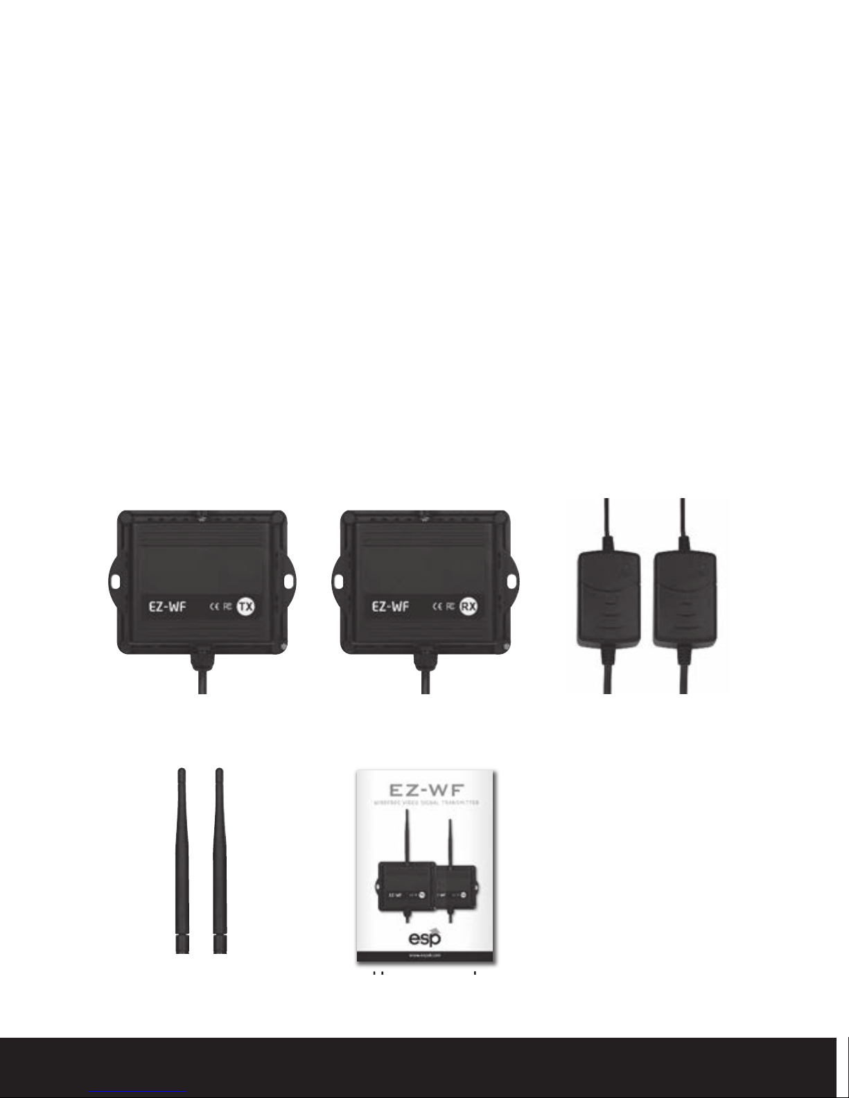
Table of contents
System Setup and Usage Guide . . . . . . . . . . . . . . . . . . . . . . . . . . . . 4
Locating the TX and RX modules . . . . . . . . . . . . . . . . . . . . . . . . . . . 6
Installation – TX module . . . . . . . . . . . . . . . . . . . . . . . . . . . . . . . . . . . 7
Installation – RX module . . . . . . . . . . . . . . . . . . . . . . . . . . . . . . . . . . . 8
Pairing the TX and RX modules
. . . . . . . . . . . . . . . . . . . . . . . . . . . . . . . . 8
Multiple unit installations . . . . . . . . . . . . . . . . . . . . . . . . . . . . . . . . . . . . . . 9
Troubleshooting . . . . . . . . . . . . . . . . . . . . . . . . . . . . . . . . . . . . . . . . . . 9
Technical specification . . . . . . . . . . . . . . . . . . . . . . . . . . . . . . . . . . . 10
Contents
TX Transmitter module RX Receiver module 2 x12 VDC
2 x Antenna
power adapter
User manual
3
Page 4
LOCAL MONITOR
12VDC
150m OPEN FIELD
12VDC12VDC
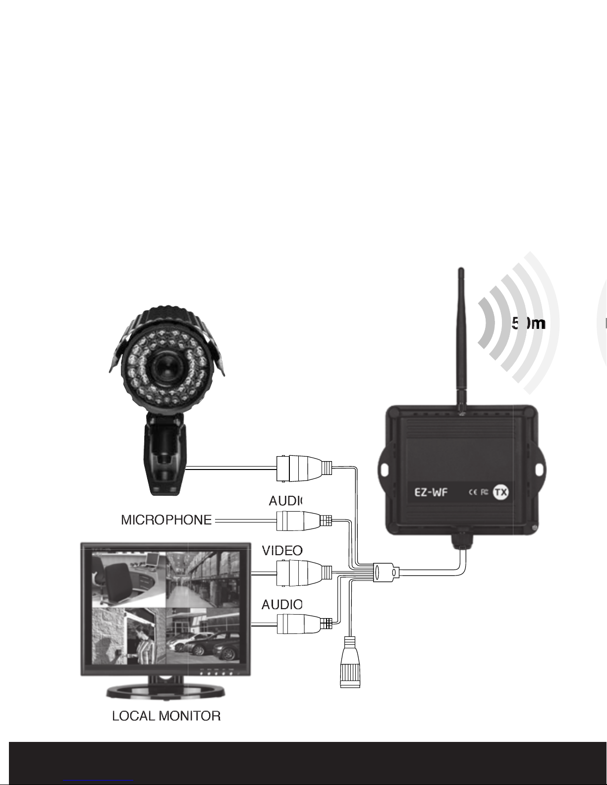
EZ-WF - Wire free digital CCTV link System Setup
and Usage Guide
The EZ-WF is a 2.4GHz Digital transmitter / receiver system that
creates a reliable and exceptionally easy to install wireless
communications link indoors or outdoors for video and audio.
n Dynamic frequency selection 2.4000 GHz to 2.4835 GHz
n Up to 150M open field range
n Stable digital signal
n IP66 rated weatherproof housings suitable for exte
n 3dB omnidirectional antenna
CAMERACAMERA
CAMERA
VIDEO IN
VIDEO IN
rnal use
MICROPHONE
4
AUDIO IN
VIDEO OUT
AUDIO OUT
POWER IN
POWER IN
POWER IN
Page 5

EZ-WF is designed to create a wire free link for a single camera
DVR
12VDC
DVR
DVR
12VDC
DVRDVR
however up to four EZ-WF units can be installed in close proximity
without interference. To gain maximum range capability the transmitter
and receiver units should be mounted within direct line of site of each
other. Both transmitter and receiver are IP66 rated and therefore
suitable for external use however all wired connections should be made
in a separate IP rated waterproof enclosure.
POWER IN
POWER IN
VIDEO 1 OUT
VIDEO 1 OUT
AUDIO 1 OUT
AUDIO 1 OUT
VIDEO 2 OUT
VIDEO 2 OUT
AUDIO 2 OUT
AUDIO 2 OUT
MONITOR
5
Page 6

Locating the TX and RX modules
To achieve a strong stable signal and maximum possible range carefull
thought must be made with regard to the location of the TX and RX
modules.
To achieve maximum range there should be a clear line of sight
between the TX and RX modules. Ideally when creating a link between
buildings the modules should be mounted on external walls opposite to
each other.
UP TO 150m OPEN FIELD
Mount the units as h
line of site transmissions such as vehicles and pedestrians.
Mount the units so that arerials are vertical at the top of the unit.
6
igh as possible to avoid temporary blockages in
Page 7

Be aware the unit requires 12vdc power which can be provided by the
included power supply unit or an alternative source rated at 12vdc @ 1amp.
Try to avoid locating the modules in close proximity to sources of
electrical equipment that may give radiated interference such as
microwaves and high voltage cables.
Video and, if available, Audio outputs from the camera and microphone
are connected directly t
e TX module. Connections are also available
o th
for a local monitor or test monitor during set up.
Installation – TX module
1. Screw an antenna onto the connector
at the top of the TX module.
ANTENNA CONNECTOR
2. Mount the TX module using appropriate fasteners to a solid mounting
surface.
3. Complete the connections to the video and/or audio source to the
video and audio in. A video and audio out is also provided to co
nnect to
ocal monitor or test monitor.
a l
RCA connector AUDIO IN
AUDIO OUT
BNC connector VIDEO IN
VIDEO OUT
POWER
7
Page 8

Installation – RX module
4. Screw an antenna onto the connector at the top of the RX module.
5. Mount the TX module using appropriate fasteners to a solid
mounting surface.
6. Complete the connections between the two video and audio outputs
to the monitors or recording devices as required.
RCA connector AUDIO OUT 1
AUDIO OUT 2
BNC connector VIDEO OUT 1
VIDEO OUT 2
POWER
Pairing the TX and RX modules
The TX and RX modules of each EZ-WF set are factory configured to pair
only with each other. The pairing will occur automatically after
approximately 30 seconds after powering both the TX and RX units as
long as they are within range. If pairing is lost it can be re-established by
powering off, then powering on one or both of the modules. After
powering off either module, wait 10 seconds before powering it on again.
8
Page 9

Multiple unit installations
Up to four sets of EZ-WF can be located within range of each other
however please ensure a minimum distance of 30cm between units
from different pairs.
During commissioning initially power each pair separately allowing
sufficient time for auto pairing . Check pairing has been achieved (Video
and audio if required) before powering second and subsequent pairs.
NOTE lf multiple s
lost between one or more TX/RX module pairs, power off the modules
of the pairs that failed, then power on each pair one at a time and allow
it to synchronize before powering on another pair.
ms are setup in the same vicinity and pairing is
yste
Troubleshooting
PROBLEM POSSIBLE SOLUTIONS
No video or audio • Check power and A/V Cable connections.
• Verify that the TX and RX module are powered on.
• Verify th
applied to the TX module.
• Verify that the recording/video monitoring
equipment is functioning properly.
Interference • Adjust the orientation of the antennas on the
at vid
eo and audio source signals are
in video TX and RX modules.
• Move the equipment away from devices that emit
high radiation, such as microwave ovens, wireless
phones, etc.
9
Page 10

Technical specification - System
Transmission channels 80 channels, auto selected
Video bit rate Up to 12Mbps
ID codes Up to 4 Million
Video resolution 720 x 480 @ 30fps
Operational range 150m open field
Technical specification - TX Transmitter module
Operating frequency 2.4000 GHz – 2.4835 GHz
Transmit power 100 Mw (MAXIMUM)
Modulation 16 QAM / QPSK / BPSK
Video input level 1 ± 0.2 Vp-p @ 75 Ω
Audio input level 1 ± 0.2 Vp-p @ 600 Ω
Antenna Omnidirectional
Power consumption 1.9 W
Power adapter 12 VDC / 1A
Dimensions (W x D x H) 159.5mm x 136.4mm x 34.8mm
without antenna and drop cable
Weight 19 oz (538 g)
Technical specification - RX Receiver module
Operating frequency 2.4000 GHz – 2.4835 GHz
Receiver sensitivity -85 dbm minimum
Video output level 1 ± 0.2 Vp-p @ 75 Ω
Audio output level 1 ± 0.2 Vp-p @ 600 Ω
Antenna Omnidirectional
Power consumption 1.9 W
Power adapter 12 VDC / 1A
Dimensions (W x D x H) 159.5mm x 136.4mm x 34.8mm
Weight 19 oz (538 g)
10
without antenna and drop cable
Page 11

11
Page 12

Elite Security Products
Unit 7, Target Park, Shawbank Rd
Lakeside, Redditch B98 8YN
Telephone: 01527 51 51 50
Fax: 01527 51 51 43
email: info@espuk.com
 Loading...