

ESP EZ-TAG2 User Manual
USER MANUAL
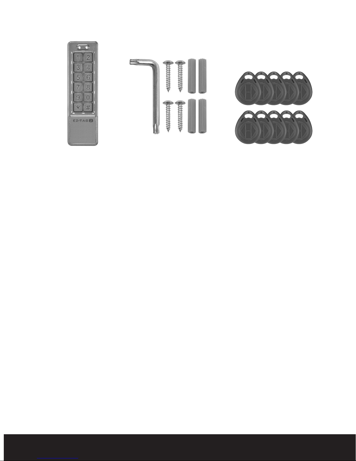
Contents
1 x Security Torx Key
4 x Screws and raw plugs
and Back Plate
Equipment required for controlling one door:-
12 volt DC power supply 2 amp minimum (EV-BPS)
1 x Marking out template
10 x TagsEZ-TAG2
Lock - Magnetic (EVML-250)/Yale type keep 12 volt lock (enter D)
Push to exit button (EVEXIT)
Green break glass emergency release (EVEBG)*
*Note:- for use with Magnetic lock only
Functions of the EZ-TAG2
The EZ-TAG2 can control up to two doors by use of Tags or pin
numbers
Selectable Pin number length 2, 3, 4, 5 and 6 digits (per zone).
Programmable door open time 00 to 99 seconds.
Two locations (zone 1, zone 2) are available for programming Tags
and Pin numbers.
1000 Tags or Pins can be programmed for zone 1.
10 Tags or Pins can be programmed for zone 2.
Two volt free change over relays one per door.
Door closed function (contact required).
2 push to exit button inputs, one per zone.
Programmable volt free change over relay for door bell function.
Programmable rear tamper.
Internal buzzer for tamper monitoring (auto cut off after 1 minute).
2
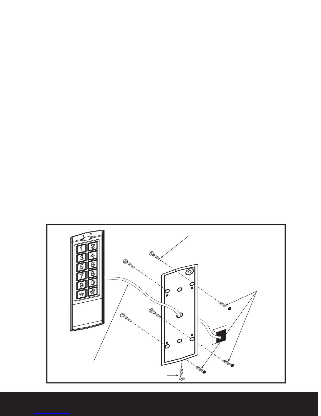
Sighting Of The EZ-TAG2
System wiring
Screw
raw plugs
Screws
Torx Screw
The EZ-TAG2 must not be located within 2 meters of any
reader/keypad type devices.
The EZ-TAG2 must not be sited back to back with other reader/keypad
type devices.
Site the EZ-TAG2 within easy access to the door/doors to be controlled
Recommended mounting height 1.2m.
Fitting
Using the template mark and drill the fixing and cable entry holes.
Remove security screw from the underside of the keypad/reader and
remove back plate.
Fit and secure the back plate in its final position. (See Fig. 1)
Feed the cable from the keypad/reader though the centre hole of the
back plate.
Clip the top of keypad/reader onto the back plate and secure using the
security fixing screw located on the underside of the keypad/reader.
Make all wiring connections and connect 12 volts DC to the keypad/reader.
The green power LED will now be illuminated on the front of the
keypad/reader.
Fig. 1
3

Yellow-push to exit button - Zone 2
Additional power
supply for lock
Brown-door status detecting - reed switch
Orange-push to exit button - Zone 1
Green - COM
Not Used
Not Used
Exit button - Zone 2
Exit button - Zone 1
COM
Door contact - reed switch
Wiring Diagram and connections
4
 Loading...