

Page 1
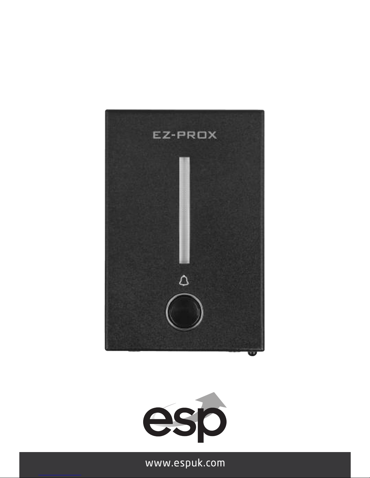
EZ-PROX
S I N G L E D O O R P R O X I M I T Y D O O R E N T RY
U S E R M A N U A L
Page 2
Contents
Equipment required for controlling one door:
12 volt DC power supply 2 amp minimum (EV-BPS)
Lock - Magnetic (EVML-250)/Yale type keep 12 volt lock (enter D)
Push to exit button (EVEXIT)
Green break glass emergency release (EVEBG)*
*Note:- for use with Magnetic lock only
Functions of the EZ-PROX
The EZ-PROX can control one door by use of tags.
Programmable door open time 00 to 99 seconds.
1000 Tags can be programmed.
Door closed function (contact required).
Programmable rear tamper.
Internal buzzer for tamper monitoring (auto cut off after 1 minute).
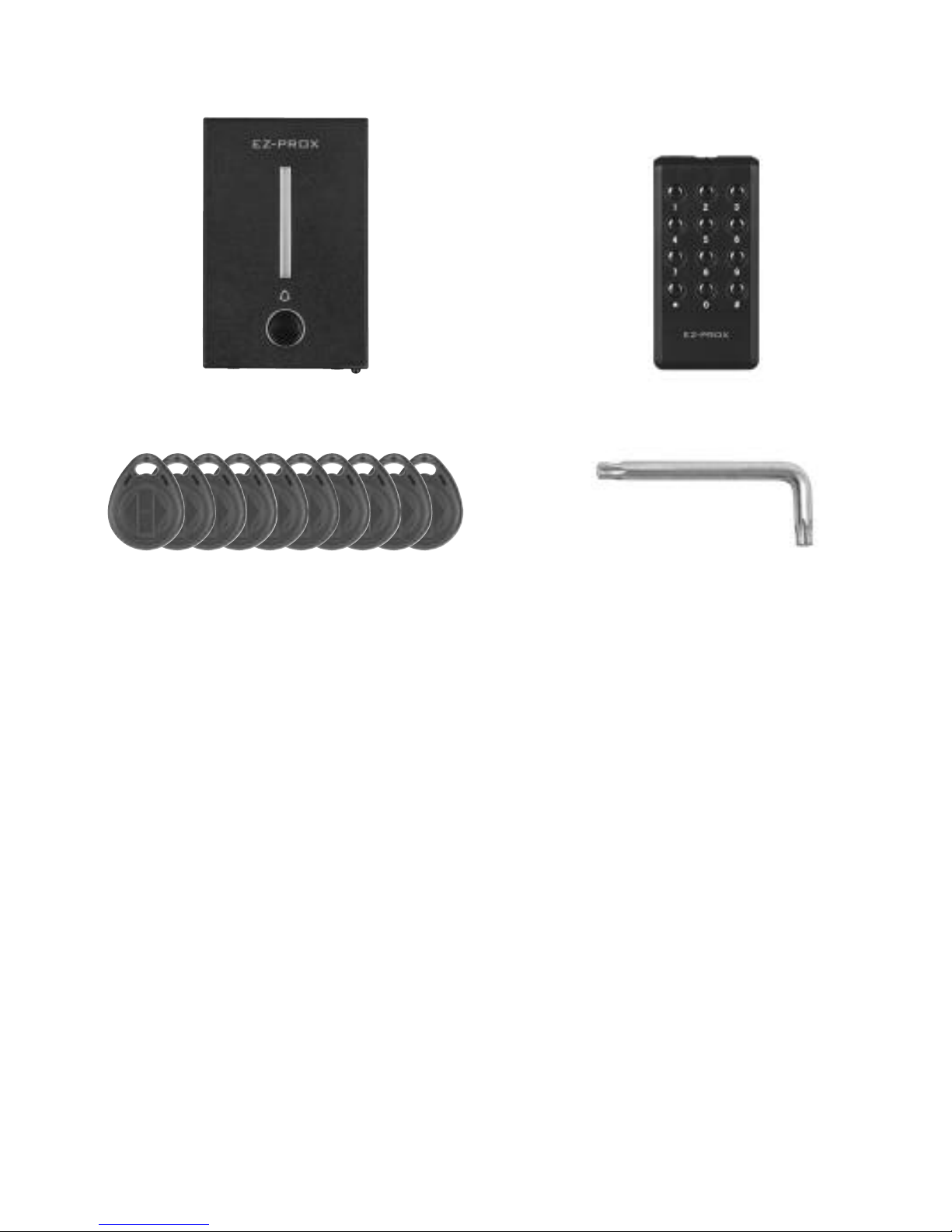
10 x Tags Security Torx Tool
EZ-PROX and back plate EZ-PROX programmer
Page 3

Screw
Screw
Screw
Screw
Screw
Screw
Screw anchor
Back cover
Hole
Hole
Indicator
114mm
75mm
20
Bell button
Remote control
IR sensor
Sighting Of The EZ-PROX
The EZ-PROX must not be located within 2 meters of any
reader/keypad type devices.
The EZ-PROX must not be sited back to back with reader/keypad
type devices.
Site the EZ-PROX within easy access to the door/doors to be
controlled
Fitting
Using the template mark and drill the fixing and cable entry holes.
Remove security screws from the underside of the reader and
remove back plate.
Fit and secure the back plate in its final position. (See Fig below)
Feed the cable from the reader though the centre hole of the back
plate.
Clip the top of reader onto the back plate and secure using the
security fixing screws located on the underside of the reader.
Make all wiring connections and connect 12 volts DC to the reader.
The power LED will now be illuminated on the front of the reader.
Page 4
DC
05D390K
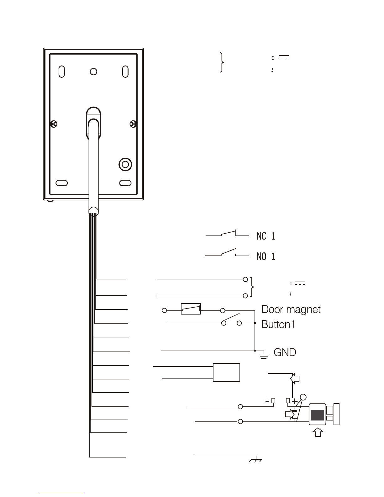
DC input +12V - +24V
AC input ~ 12V - 24V
Red-power DC input +12V - +24V
Black-power AC input ~ 12V - 24V
Brown-door status detecting reed switch
Orange-push to exit button
Yellow-DATA 1
Green-GND
Blue-Door bell
Purple-Door bell
Gray-DATA 0
White-NO 1
Pink-COM 1
Aqua-NC 1
Shielded ground
DATA 1
NO 1
COM 1
NC 1
DATA 0
Shielded ground
Red
Black
Brown
Orange
Yellow
Green
Blue
Purple
Gray
White
Pink
Aqua
Wiring Diagram
Page 5
RED
BLACK
WHITE
PINK
Exit Button
0-20
L N
E.lock
+ -
DC out
+ -
Push button
GND P.B
N.O
Timer
secs
240vAC
INPUT
EV-BPS
Yale Release
Exit Button
0-20
L N
E.lock
+ -
DC out
+ -
Push button
GND P.B
N.C
Timer
secs
RED
BLACK
WHITE
PINK
INPUT
EV-BPS
Maglock
Emergency
door release
COM
N.C
Capacitor
0.47uF
100v
240vAC
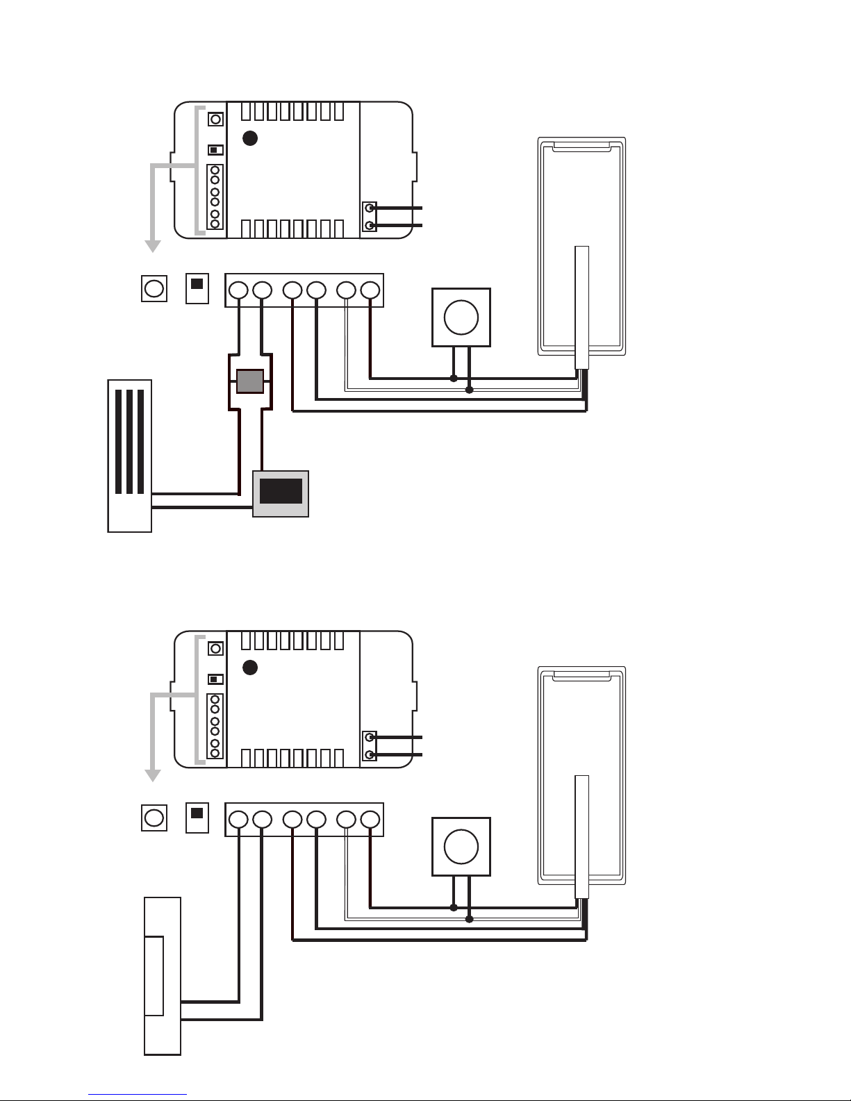
Wiring Diagram for Maglock
Wiring Diagram for Yale Release
Page 6

How to enter programing mode
Factory default programming code is 1234.
Input the programming code twice (1234 and1234), the yellow
LED will be on. To exit programming mode press # button.
Programming a fob or card
Note:- Do not have Tags in your hand or close by when pressing
keys.
EZ-PROX has 1000 locations available from 000 to 999.
1. Enter programming mode the blue LED will turn yellow.
2. Enter the location you want to programme the Tag to in a 3
digit format (xxx). A green light will show the location is empty
and ready to present a tag if a red light is present this location
is already in use. To delete this location press the star * key
twice. The LED will now turn green.
3. Pick up one Tag only and present it to the bottom of the reader
( ) and remove. A bleep will be heard this means the card or fob
is added. If further Tags are to be programmed select the next
available location number (xxx)
Deleteing a fob or card
Enter programing mode.
Enter any 3-digit number from 000 to 999 (yellow light will blink
during this process): if the LED changes to red there is data stored,
green shows the location is empty. Press * twice to delete the
stored location.
Press # to quit setting mode.
Page 7

Programing a group of fobs or cards
Enter programing mode.
1. All tags to be programed as a group must have consecutive
numbers.
2. Press the * key then the 9 key the yellow light will flash
3. Press the 0 key then the 1 key the unit will bleep once.
4. Enter the number of the first available location in the range of
000 to 999.
5. Now enter in a 3 digit format how many tags you want to
programme (xxx) into the system, present the lowest number
tag to the reader ( ) and remove. Alternatively enter the 8 digit
number of the lowest number Tag from the group to be
programmed into the keypad.
To confirm the programming has been successful 2 bleeps will
be heard.
Press # to exit the setting mode.
Set door open time
1. Enter programming mode.
A Long bleep will be heard and the blue power LED will turn
yellow.
2. Press the * key then the 1 key the yellow LED will start to flash
3. Enter the time in seconds for the unlock time from 00 to 99
seconds.
Press # to exit the setting mode.
The tamper alarm
The built-in buzzer will sound a continuous Bleep Bleep. If the
photoresistor sensor is directly exposed to the light. The buzzer
will turn off automatically after 60 seconds, or when the light is
no longer detected, or by entering the programming code.
Page 8

Changing the Programming code
1. Enter programming mode.
A Long bleep will be heard and the blue power LED will turn
yellow.
2. Press * key followed by the 3 key the orange LED will start to
flash.
3. Enter the new programming pin twice.
A conformation bleep will be heard.
4. Press * 3 (yellow light blinks). Then input new administrator
code twice (The length of the new admin code must be the
same as the old one). Bleep - sound means it modifies
successfully.
Press # to exit the setting mode.
Turn on/off the rear tamper alarm
The rear tamper function consists of a photoresistor at the rear of
the unit. When this function is enabled the unit will emit a
continuous bleep if exposed to light.
The continuous bleep will stop automatically after 60seconds or if
the unit is no longer exposed to light.
You can cancel the continuous bleep by enter the programing
code.
1. Enter programming mode.
2. To turn on the rear tamper alarm.
Press * then 6 the yellow light will flash.
Press 0 then 2 the yellow light no longer flashes and the unit
will bleep.
Press # to exit the setting mode.
Page 9

Delete all user fobs and cards and restore to
factory default
Enter programming mode.
1. A Long bleep will be heard and the blue power LED will turn
yellow.
2. Press * key followed by the 8 key theyellow LED will start to
flash.
3. Press the 8 key twice.
7 conformation bleeps will sound.
Set the (digit) length of password
1. Enter programming mode by entering the 4 digit pin number
twice (default pin 1234).
A Long bleep will be heard and the blue power LED will turn
yellow.
2. Press the * key followed by 9 key the orange LED will now
flash.
3. Press 04 a long bleep will be heard.
4. Enter the length of the pin number you require (2,3,4,5 or 6).
If the length is the same as already programmed you will get a
conformation bleep.
If you have changed the length you will get 7 bleeps to say it has
now been changed.
Note:- Any pin numbers or Tags programmed into the system will
be deleted if the pin length is change.
Press # to exit the setting mode.
Page 10

Technical Specifications
Working temperature -10 ~ +55ºC
Voltage DC: 12V-24V AC: 12V~24V
Working current <120mA
Standby current <90mA
Card mode ID / IC card
Effective distance <5CM
Capacity 1000 Cards or Fobs
Elite Security Products
Tel: 01527 515150
Fax: 01527 515143
email: [email protected]
 Loading...