

Page 1
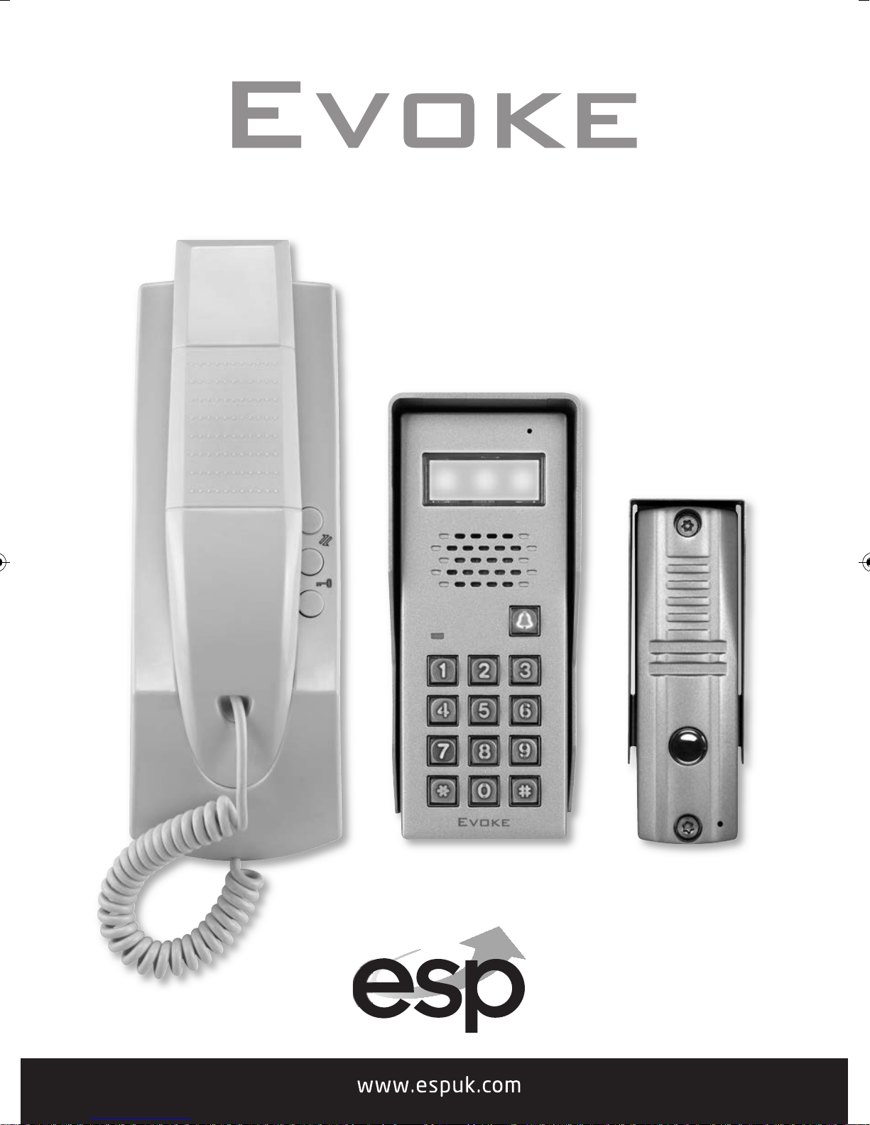
AUDIO DOOR ENTRY SYS TEM S
Page 2

Please note this manual covers both the
Evoke and Evoke KP models.
Contents
Product Descriptions and Technical Specifications . . . . . . . . . . . . . . . . . . . . . . . . . . 3
Evoke Call Point and Evoke Handset Installation . . . . . . . . . . . . . . . . . . . . . . . . . . . . 4
Evoke Call Point and Evoke Handset Wiring . . . . . . . . . . . . . . . . . . . . . . . . . . . . . . . . . 5
Evoke KP Call Point and Evoke Handset Installation . . . . . . . . . . . . . . . . . . . . . . . . . 6
Evoke KP Call Point and Evoke Handset Wiring . . . . . . . . . . . . . . . . . . . . . . . . . . . . . . 7
Operating Evoke / Evoke KP . . . . . . . . . . . . . . . . . . . . . . . . . . . . . . . . . . . . . . . . . . . . . . . 8
Evoke KP Programming . . . . . . . . . . . . . . . . . . . . . . . . . . . . . . . . . . . . . . . . . . . . . . . . . . . 8
2
Page 3
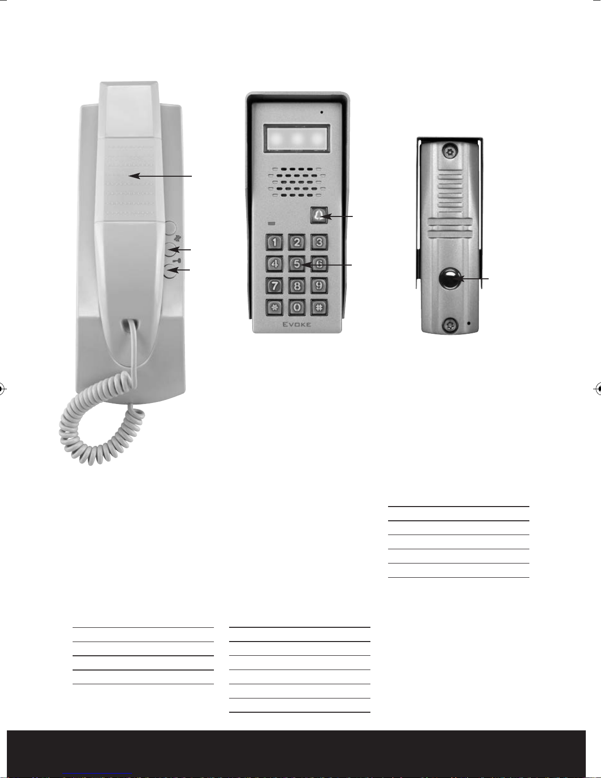
Product Descriptions and Technical Specifications
Handset
Calling
Button
Extension
call
transferring
Unlock
Keypad
Calling
Button
Evoke/KP Handset
Clear 2-way audio
Easy lock-release facility
2 handsets require 1 PSU
Distinctive ring tone
Call transfer facility
Operating voltage 14 VDC
(transformer supplied)
Internal use only
Technical Specification
Input range DC12V
Output power <=0.6W
Working current <=50mA
Dimension 225 x 83 x 60mm
Evoke KP Call Point
(Requires 12 VDC PSU - EVBPS)
Keypad door access
Up to 30 programmable
pin codes
Up to 10 latching pin codes
Voltage free change-over
contacts
Quick grip cable termination
Push-to-exit input
Blue backlit keypad
Weather shield
Metal fi nish
IP55
High-gain microphone
Clear 2-way audio
4 core required to indoor
handset
Technical Specification
Input range DC12V
Output power <=1.56W
Working current <=130mA
Speaker output 0.5W
IP rating 55
Dimension 190 x 78 x 60mm
Evoke Call Point
Clear 2-way audio
Single call button
Weather shield
Metal finish
IP55
High-gain microphone
2 core required to indoor
handset
Technical Specification
Input range DC12V
Output power <=0.6W
Working current <=50mA
IP rating 55
Dimension 128 x 43 x 40mm
3
Page 4

Evoke Call Point Installation
113 mm
1. Distance of each fixing screws as shown below. Mark fixing screw positions and cable entry hole.
2. Drill fixing and cable entry holes and mount steel wall plate.
Connect incoming cable to the red/black on camera.
3. Fit hood and door call unit and secure to wall using the enclosed security fixing screws.
Fig. 2
Evoke Handset Installation
1. Fasten the steel mounting bracket on the wall.
Then connect incoming cable to the 4 core brown plug.
2. Hang the indoor handset on the steel mounting bracket.
Fig. 1
4
Page 5

Evoke Call Point System Wiring
Evoke Handset(s) with Call Point
Additional accessories required for door control
2 Core 2 Core
4 Core
240V AC
EV-BPS
2 Core 2 Core
2 Core2 Core
240 AC
2 Core
EV-EXIT
EVBPS wiring
Lock selector switch
N.O = Yale
N.C = Mag Lock
LOCK
From Handset +
Push to Exit Button - EVEXIT
1
2
3
4
5
6
Evoke Handset to Evoke Call Point Wiring
Evoke Handset with Evoke Call Point
EV-EBG
EV-ML250
Handset 1 Handset 1
Red
P2
Black
P2
Red
Black
P1
White
P1
Purple
Red
Black
Red
Black
White
Purple
240V AC
LOCK
Lock selector switch
N.O = Yale
N.C = Mag Lock
1
2
3
4
5
6
5
Page 6

Evoke KP Call Point Installation
Water cover
Screw
Screws
(Requires 12 VDC PSU - EVBPS)
1. Select a suitable location to mount the outside
door station. Mark the fixing and cable entry
holes, the shroud can be used as a template for
this. Once all holes are drilled feed cable
through the wall
2. Place the raw-plugs into the drilled holes, and
fix the water cover to the wall using the screws.
3. Connect incoming cable to the term
the rear of the keypad.
4. Fit the keypad to the water cover and secure
using the bottom securing screw.
al strip on
in
Evoke KP Handset Installation
1. Fasten the steel mounting bracket on the wall.
Then connect incoming cable to the 4 core brown plug.
2. Hang the indoor handset on the steel mounting bracket.
Fig. 4
Fig. 3
6
Page 7

Evoke KP Call Point System Wiring
Evoke Handset(s) with Keypad
Additional accessories required for door control
4 Core
2 Core 2 Core
240 AC
EVBPS wiring
Lock selector switch
N.O = Yale
N.C = Mag Lock
LOCK
From Handset +
Push to Exit Button - EVEXIT
2 Core
1
2
3
4
5
6
EV-BPS
2 Core
EV-EXIT
240V AC
2 Core4 Core2 Core
EV-EBG
2 Core
EV-ML250
Evoke Handset to Evoke KP Wiring
Evoke Handset with Evoke Keypad
Handset
Terminals
P2
P1
Red
Black
Red
Black
White
Purple
Keypad
Terminals
1
2
3
4
5
6
7
8
9
10
240V AC
LOCK
Lock selector switch
N.O = Yale
N.C = Mag Lock
1
2
3
4
5
6
7
Page 8

Operating Evoke / Evoke KP
Calling:
Press the call button to call the indoor monitor.
The speaker of the indoor monitor sounds and
the indicator light flashes.
Talking/listening
Pick up the handset to talk with the visitor.
Pick up the handset to listen to the outside or
talk to the outside door station
Replace the handset to end the call.
Unlocking:
Press the button to unlock the door
Extension call transfering:
To transfer an incoming call to another handset
press this will call all other handsets
on the system.
Evoke KP Programming
Default Programming Code: 1234
Before the keypad will work to open the
door a user pin will be needed to be
programmed in to the system.
Enter the programming mode
1. Press *“bleep” should be heard twice, then
enter the 4-digit programming PIN number,
“b
leep” should be heard three times with LED
light flashing. This indicates that entry to the
programming mode has been successful.
2. Press
“bleep” will sound five times.
Add user PIN numbers
1. Enter the programming mode first.
2. Enter 01 - 40 (location 31 - 40 are for latching
PIN numbers only).
3. Enter the new 4 digit PIN number, if
successful the “bleep” will sound three times.
If when entering the new 4 digit PIN number a
long “bleep” is heard twice, this indicates that
this number is already in use on the system.
The keypad will now return to the
programming mode.
to exit the programming mode the
*
Delete user PIN numbers
1. Enter the programming mode first.
2. Enter the allocation number you want to
delete from 01 - 40.
3. Press # to delete the PIN number stored
allocation number 01- 40.
4. After “bleep” is heard three times, this
confirms PIN number has been deleted and
returns to the programming mode.
Delete user PIN numbers directly
1. Enter to the programming mode first.
2. Press #. After “bleep” is heard twice, then
enter the 4-digit PIN number for deletion.
3. After “bleep” is heard three times, this
confirms PIN number has been deleted and
returns to the programming mode.
Delete all settings
1. Enter the programming mode first.
2. Press #. After “bleep” is heard twice, press #
again. Another “bleep” is heard twice.
3. Then, press # for a further seven times, the
system deletes all the setting. The unlocked
time changes to 1 second, and the
programming PIN number does not change.
After hearing “bleep” for five times, the
system is now reset, and all the user PIN
numbers are deleted.
Set unlocked time
Factory default setting is 5 seconds.
1. Enter the programming mode first.
2. Enter code 00, and the “bleep” should be heard
twice.
3. Enter the unlocked time: 2 digits (01 - 99
seconds); 00 is not valid in this mode.
4. After “bleep” is heard for three times, it will
return to the programming mode.
5. Press
to exit the programming mode.
*
Set programming code
1. Switch off the power, press *and hold,
switch on t
“bleep”, release *.
2. After the long “bleep” stops, another “bleep” is
heard, now you can enter the new 4-digit
programming PIN number.
3. After entering the new PIN number, a “bleep”
will be heard for 5 times.
he power. After hearing a long
Telephone: 01527 515150 www.es p u k .com
 Loading...