

ESP Enterview MX EVMX2, Enterview MX EVMX2C, Enterview MX EVMX4, Enterview MX EVMX4C, Enterview MX EVMX6 Instruction Manual
...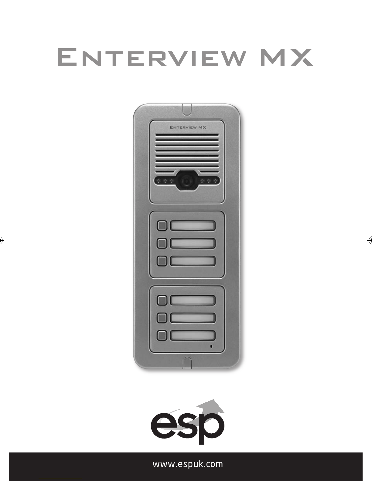
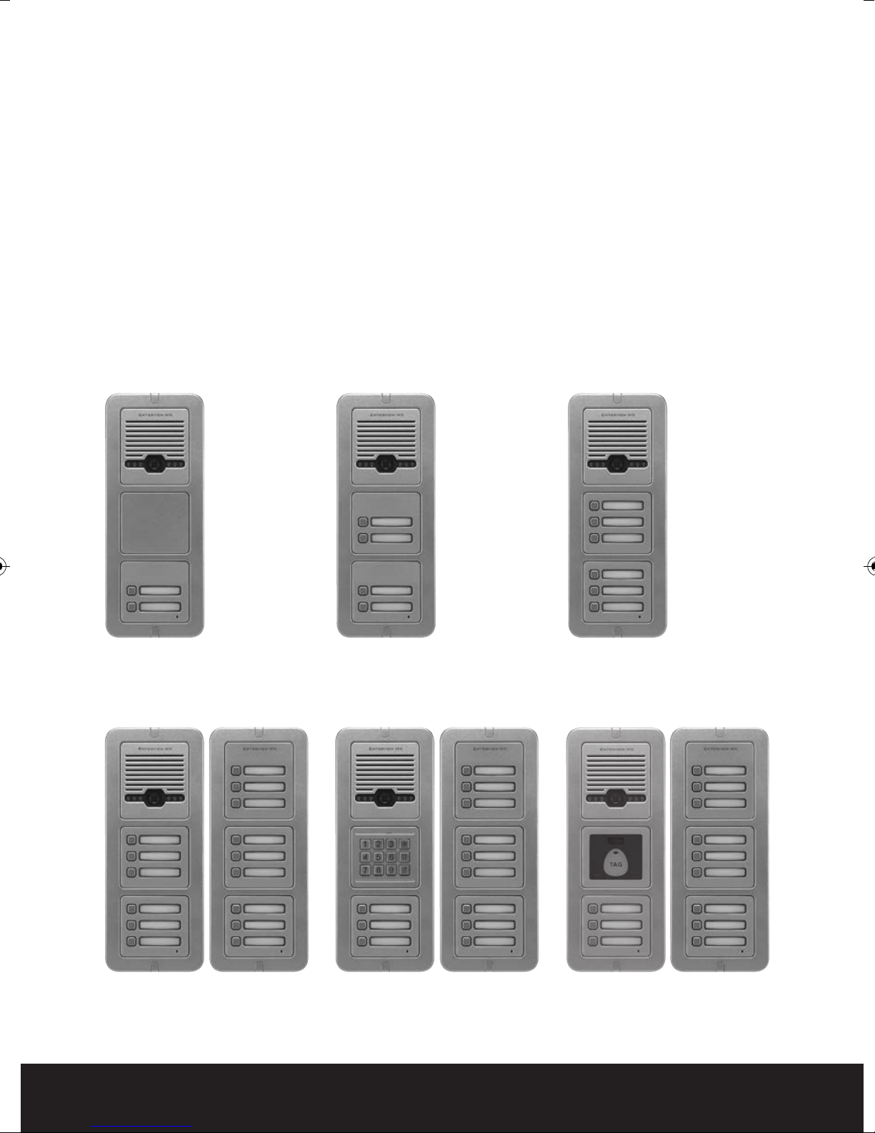
Table of contents
Planning and installing the Enterview MX . . . . . . . . . . . . . . . . . . . . . . . . . . . . 3
Fitting and wiring the external call station . . . . . . . . . . . . . . . . . . . . . . . . . . . 4
External call station internal wiring connections . . . . . . . . . . . . . . . . . . . . . 6
Trade Button . . . . . . . . . . . . . . . . . . . . . . . . . . . . . . . . . . . . . . . . . . . . . . . . . . . . . . . 7
Fitting and wiring the Handset . . . . . . . . . . . . . . . . . . . . . . . . . . . . . . . . . . . . . . 8
System schematic wiring diagram . . . . . . . . . . . . . . . . . . . . . . . . . . . . . . . . . . . 9
Programming the keypad . . . . . . . . . . . . . . . . . . . . . . . . . . . . . . . . . . . . . . . . . . 10
Programming the proximity reader . . . . . . . . . . . . . . . . . . . . . . . . . . . . . . . . . 12
Trouble Shooting Guide . . . . . . . . . . . . . . . . . . . . . . . . . . . . . . . . . . . . . . . . . . . . 14
EVMX2 or EVMX2C
2 way mono or colour video
door entry call station
Example of a 15 way video
door entry call system
EVMX4 or EVMX4C
4 way mono or colour video
door entry call station
Example of a 12 way video
door entry call system with
keypad
EVMX6 or EVMX6C
6 way mono or colour video
door entry call station
Example of a 12 way video
door entry call system with
proximity reader
2

Planning and installing the Enterview MX
Planning your MX Door Entry System
External call station
How many Entry Doors (Front or/and Rear)
Audio only or with Video
Monochrome/ colour
Integral Key pad
Mounting Flush or surface
Integral Proximity Reader
External Call buttons (one per dwelling)
Trade entry control
Combined timed Lock and outdoor call station power supply (EVBPS)
le distance per external call button to each handset is 100
Note: The maximum
meters using CAT5e cable. The maximum distance per supplied power supply
to each handset is 10 meters using 2 pairs of CAT5e cable.
Equipment required
External call station (one required per door)
cab
Maximum of 6 call buttons without an expander
Expander (if required) maximum of 9 call button per expander
D
External call station power supply
Handset EV5H/EV5HF (minimum of one per external call button)
Electric lock magnetic (ML250)/Yale type (enter D)
CAT5e cable minimum 4 cores (see Note above regarding cable distances)
Push to exit button (one required per door if magnetic lock used)
Emergency break glass green
(One required per door if magnetic lock used and the door is deemed an
emergenc
H
andsets
Audio/video or Audio only note:- minimum of one per external call button
Monochrome/colour picture
Standard or hands free unit
Door Gear
Power supply with timed output (EVBPS)
y exit)
C 12 volts (EVBPS) (one required per door)
Magnetic lock/Yale type lock
Push to exit button
Emergency break glass green (only needed when magnetic lock fitted and to an
emergency exit door)
3
Basic cabling
240 VAC mains feed to external door and lock control power supply (EVBPS)
240 VAC mains feed to each handset (via transformer- supplied)
4 core from each external call station (front/rear) to its own power supply (EVBPS)
CAT5e from each external call station (front/rear) to each handset
4 core from push to exit button to EVBPS (power supply)
4 core from lock to EVBPS (power supply
4 core
2 pairs of CAT5e from supplied power supply to each handset
Note: The maximum cable distance per external call button to each handset is 100
from EVBPS (power supply) to emergency break glass (if fitted)
meters using CAT5e cable. The maximum distance per supplied power supply
to each handset is 10 meters using 2 pairs of CAT5e cable.
)
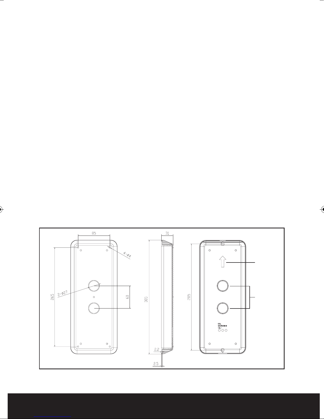
Fitting the external call station
Location
Select a location cl
Recommended mounting height 1.45 meters (camera lens)
Secure back plate to the wall paying attention to the upward facing arrow located
on the back plate (see Fig. 1 item 1 for surface and Fig. 2 for flush mounting)
Feed cables from each apartment and the power supply through the cable entry
hole see Fig. 1 item 2
Trim cable length to approx. 200mm
ose to the door to be controlled
Fig. 1
4
Item 1
Item 2

Fig. 2
1
2
3
4
5
6
Wiring the external call station
Each call button will have its own brown 4 core connector (supplied) consisting of
red, blue, yellow and white cores.
The 4 colours that are connected to the brown connector are to be connected to
the corresponding 4 core cable going to each of the apartments.
The connection can be completed by means of soldering, crimping or by use of
screw connectors.
To power
the camera, keypad and call station a 12 volt DC feed is required. To do
this a white two pin plug consisting of red and black cores supplied should be
connected to the corresponding cable going to the EVBPS power supply. Connect
to terminals 3 and 4 (DC 12V) in the EVBPS Fig. 3. Fit the white plug into the white
2 pin socket located at the lower part of the door station Fig. 4.
Th
e two single black
These are volt free and are normally open going closed. These contacts will
change state on the lock release command. The two black cables from the hand
sets need to be connected to the 4 core cable going to the EVBPS and connected
to terminals 5 and 6 (P.B) on the EVBPS Fig. 3.
Connect to
Door Lock
Connect two black
wires from Main Panel
cab
les on the external call station are for the lock release.
Fig. 3
5
 Loading...