

Page 1

1 of 34
V 1.0
www.esavep.com
ECOCENT 250 T & 250 T2
Installation and Operation
Manual
Page 2

2 of 34
V 1.0
www.esavep.com
WARNING !
READ THIS BEFORE INSTALLING THE UNIT
All un-vented water heating systems above 15 litres (this includes the ESP Ecocent Hot Water ASHPs)
MUST be installed to meet the requirements of the local area Building Regulations. It is a legal
requirement that the local Building Control Officer be notified of any proposed installation of unvented water heating systems over 15 litre capacity. This Ecocent unit must be installed and operated
in accordance with EN 806.
Furthermore, it must be fitted by an installer who has successfully completed a recognised course in
the installation of un-vented heating systems such as CITB and be familiar with installing the Ecocent
unit. Failure to properly fit the unit may affect its safety, efficiency and invalidate any guarantee.
Safety requirements in the UK call for an expansion space (internal or external), safety devices to
prevent the stored water exceeding 100°C and pipe work to convey discharged hot water safely away
from the safety devices.
THE UNIT MUST BE INSTALLED, COMMISSIONED AND MAINTAINED BY A COMPETENT INSTALLER IN
ACCORDANCE WITH BUILDING REGULATION G3 (ENGLAND AND WALES), TECHNICAL STANDARD P3
(SCOTLAND) OR BUILDING REGULATION P5 (NORTHERN IRELAND) AND THE WATER FITTING
REGULATIONS (ENGLAND AND WALES) OR WATER BYELAWS (SCOTLAND). FOLLOWING INSTALLATION
AND COMMISSIONING, THE OPERATION OF THE UNIT SHOULD BE EXPLAINED TO THE USER AND
THESE INSTRUCTIONS LEFT WITH THEM FOR FUTURE REFERENCE.
Page 3
3 of 34
V 1.0
www.esavep.com
Contents Page
1.0
Preface
2.0
General Notes
2.1 Safety Precaution
2.2 Installation Notes
2.3 Operating Notes
2.4 Moving and Repairing notes
2.5 Operation Notes
3.0
Component Checklist
4.0
Sitting the Unit
4.1 Some notes on Ducting
4.2 Water Supply
4.3 Outlet/Terminal fittings
4.4 Limitations
4.5 Hot Water ASHP Package
4.6 Basic system schematic
5.0
Specification
5.1 Appearance
5.2 System Principles
5.3 Dimensions
5.4 Specifications
5.5 Performance
5.5.1 Performance assumptions
5.6 DHW Recovery Times
6.0
Installation
6.1 Installation Sketch Map
6.2 Indirect Thermal cut-out (dual stat)
6.3 Pipe fittings
6.4 Cold Water Supply
6.5 Cold Water Combination Valve
6.6 Drain Cock
6.7 Outlet Pipe Work
6.8 Secondary Circulation of DHW
6.9 TPRV
6.10 Warnings
6.11 Discharge Pipe Work
6.12 Expansion Vessel
6.13 G3 Requirement
6.14 G3 Guidance Section
7.0
How to connect to the Heat Pump
Page 4

4 of 34
V 1.0
www.esavep.com
7.1 Insulation Treatment
7.2 Wiring
7.3 Earthing
7.4 Unit System Controls
7.5 Immersion Heater
8.0
Operation
8.1 Control panel explanation
8.2 Controller Functions
8.3 Before running the unit
9.0
Maintenance Requirements for the Cylinder
9.1 Checking operation of safety valves
9.2 Cleaning the Strainer
9.5 Log Book
9.6 Maintenance Requirements
10.0 Simple Fault Finding
10.1 FAQs
11.0 Guarantee
11.1 Guarantee Terms
12.0 Environmental Information
13.0 Spare Parts
Page 5

5 of 34
V 1.0
www.esavep.com
1.0 PREFACE:
Icon
Meaning
Wrong operation may lead to risk to
life or serious injury.
Potential danger to you or others.
Prohibited.
Compulsory.
This manual includes the necessary information for the safe installation and maintenance of
the Ecocent. Please read this manual carefully before you install or carry out maintenance on the unit
When installing the unit, please carry out the work strictly in accordance with the manual,
relevant Regulations and good practice.
Please do not switch the unit on until you are sure that it has been properly installed (both
electrically and mechanically), there is water in the system and the tank has been completely purged
of air.
The installer must explain to the end user how to operate and maintain the unit before handing
over the unit to the end user.
The installer must advise the end user to read the manual fully before operating the unit and leave this
manual with the end user.
Further, improper installation, operation and/or maintenence , and failure to maintain the unit as per this
manual will invalidate any unit warranty or guarantee.
The manual may be altered and/or updated in any way at the sole discression of the supplier and/or
ESP without notice.
2.0 GENERAL NOTES
2.1 Safety Precautions
Below you will find information that is critical for the safe and proper installation and the use of the
unit. Please make sure that you understand the contents to help avoid the risk of injury or damage to
the unit/other property.
.
Page 6
6 of 34
V 1.0
www.esavep.com
2.2 Installation Notes
Read the
Manual
Read this entire manual before attempting to install or
operate this unit.
Do NOT
Do not push anything into the fan blades when running and
make sure that children cannot access the unit or play close
to the unit.
Children
Children should only operate this unit under the supervision
of adults.
Shut off the
power
supply
If there is an unusual sound or smell coming from the unit,
shut off the power supply immediately and call your
installation engineer.
Professional
& qualified
installer
is required
The heat pump must only be installed by a suitably qualified
engineer. Failure to ensure this can cause damage to the
unit and may cause serious injury. The warranty on the unit
will also be invalidated if a suitably qualified engineer is not
engaged to install it.
Earthing
Required
Please make sure that the unit and power supply are
properly earthed.
Refrigerant
If you are installing the unit in a small room, please give careful
consideration to adequate ventilation being available in the
event of a refrigerant leak.
Installation
Site
Do not install the unit near to a gas installation. This unit is
designed to be installed inside a building.
Site
consideration
Ensure that this unit is installed on a solid, level floor. Make
sure that you have a suitable facility to cater for disposal of
condensate from the condensate drain on the unit.
Circuit
Breaker
Make sure that this unit is connected to the power supply via
a suitably sized MCB.
Unit Upright
The unit must be installed level across the whole diameter.
Failure to install the unit level will mean that condensate can
spill over the lip of the cylinder.
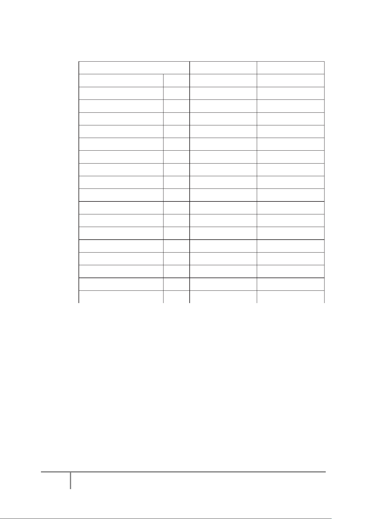
2.3 Notes on Operating your Ecocent:
Page 7
7 of 34
V 1.0
www.esavep.com
Siting the
Unit
The unit must only be installed indoors – the unit is neither
designed for, nor suitable for, installation outside. The Unit
needs to be sited where the ambient temperature never
goes below 5 degrees. If the unit is to be left unused for any
significant period of time during which the ambient
temperature could cause the unit or pipe work from the unit
to freeze, it should be drained down.
Shut off the
power
When cleaning the unit, shut off the power supply.
Power
Supply
You must use a suitable power supply that is appropriately
Fused and protected by an RCD.
Caution
This unit has a high centre of gravity. This Ecocent must be
secured to prevent it falling over when in transit.
Suitably
qualified
engineer
When moving the unit or carrying out repair work please be
sure to use only a suitably qualified engineer.
Do NOT
Do NOT try to install, move or repair the unit yourself – it is
NOT worthwhile running the risk of injury.
Transporting
the Unit
The unit must be transported in the vertical position. It can
be tilted up to a maximum 30° from the vertical axis.
2.4 Notes on moving and repairing your Ecocent:
2.5 Some Safety Notes:
2.6 General Requirements
IMPORTANT: PLEASE READ AND ENSURE THAT YOU UNDERSTAND THESE INSTRUCTIONS BEFORE
INSTALLING THE ESP ECOCENT (“DHW ASHP” OR “UNIT”). INCORRECT INSTALLATION WILL
INVALIDATE ANY GUARANTEE AND MAY BE DANGEROUS.
Page 8

8 of 34
V 1.0
www.esavep.com
PLEASE NOTE THAT THERE ARE ESSENTIALLY 2 UNITS COMBINED INTO ONE IN THE ESP ECOCENT
AND YOU MUST BE SURE TO UNDERSTAND BOTH ELEMENTS – THE INDIRECT HOT WATER
CYLINDER AND THE AIR SOURCE HEAT PUMP. PLEASE ALSO NOTE THAT THE ECOCENT CAN BE
INSTALLED IN EITHER A VENTED OR UNVENTED SYSTEM.
3.0 COMPONENT CHECK LIST
Before commencing installation of the unit, check that all the components for your unit are
contained in the package. The following components are supplied as standard with all
Ecocents to be installed in a “mains pressure” configuration:
Factory fitted immersion heater (s) and thermal controls.
Cold Water Combination Valve (comprises Pressure Reducing Valve, Stainer and
Check Valve).
Expansion Core Unit (comprises Check Valve and Expansion Valve).
Temperature/Pressure Relief Valve (set at 90 - 95°C/1 Mpa (7bar).
Tundish (included in Cold Water Combination Valve pack).
Factory fitted Indirect Thermostat and Thermal Cut-out.
4.0 SITING THE UNIT
The unit must be vertically floor mounted. It can be placed anywhere convenient provided that the
discharge pipe(s) from Safety valves and air handling duct work can be correctly installed. Areas
that are subject to freezing must be avoided. Ensure that the floor is of sufficient strength to
support the the weight of the unit when it is full of water. Pipe run lengths should be kept as short as possible
for maximum economy and efficiency : the use of secondary returns should be avoided.
Access to controls, immersion heaters and indirect controls must be maintained for servicing
and maintenance of the unit. Please do not install valves or pipe work (except discharge pipe) within 50mm
(2”) of the T&P relief valve to allow insulation to be fitted.
Consideration must be given to the use of insulated ducting to carry air to and from the unit.
Insulated ducting must used where condensate may form on the duct work.
IMPORTANT NOTE:
APPLIANCE OR IN A ROOM FROM WHICH AN OPEN FLUED APPLIANCE TAKES
ITS COMBUSTION AIR, UNLESS THE MATTER HAS BEEN CAREFULLY
CONSIDERED AND ADEQUATE DUCTING AND VENTILLATION HAS BEEN PROVIDED FOR THE
ECOCENT AND THAT THE OPEN FLUED APPLIANCE AIR SUPPLY NEEDS HAVE BEEN
CALCULATED BY AN APPROPRIATELY QUALIFIED SPECIALIST .
Please be sure to use appropriate lifting equipment when moving the unit.
DO NOT SITE THE UNIT IN THE SAME ROOM AS AN OPEN FLUED
Some things to be considered in positioning the unit:
Waste heat is useful heat (picture 1)
The Ecocent can receive ducted waste heat from another area in the building – duct work can be fixed
to the top of the unit and may be up to 8m long. Areas over 8m away can can be used if an additional
in-line fan is fitted in the ductwork. The Ecocent can also draw heat from the room in which it is sited.
Always be sure to site the unit and arrange the duct work to allow for adequate heat availability. This
Page 9

9 of 34
V 1.0
www.esavep.com
will allow the Ecocent to operate efficiently (the inlet air should not be below 7° C or above 43° C).
The optional secondary coil in the Ecocent (25T2 model) enables direct connection to a second stable
heat source, e.g. a solar heating system or a boiler.
Under no circumstances is the Ecocent to be installed onto an
uncontrolled heat source e.g wood burner or back boiler
Picture 1
Dehumidification –
Rooms (See Picture 2). The unit is equipped with a condensate drain that must be properly directed to a
suitable waste pipe where the condensate water (non acidic) can drain away. If the drain is into a main sewer
it must have a trap installed to prevent back smell through the Ecocent.
The Ecocent can be used to dehumidify rooms that are hot and damp – e.g. Laundry
Picture 2
Cooling in the re-circulating air mode
The Ecocent can extract warm air and place cooled, dehumidified, outlet air back into the same room –
this is perfect for cellars and gymnasiums. Any cold air exhaust air ducting must be lagged when
passing through a warmer area to prevent the formation of condensate. All ducting should be 150mm or split
into two 75-80mm ducts.
(picture 3)
Picture 3
Page 10

10 of 34
V 1.0
www.esavep.com
Directional cooling ducting (picture 4) can be fitted with air diverters (e.g. the ESP “Ecobox”) so that
the cool exhaust air can be directed to chosen areas.
Picture 4
Siting the Ecocent – some points:
1. Decide upon the right route to be taken to move the unit to the chosen position.
2. Where possible, move the Ecocent to its final location in its original case to avoid damage.
3. The unit and electrical connections must be installed by suitably qualified and experienced
technicians.
4. Ensure that no building materials or debris are allowed to enter the air ducts at the top of the
unit or any extension of the ducts.
5. The surface on which the Ecocent is placed must be capable of supporting the weight of the
filled unit and must be flat (≤2° from horizontal.)
4.1 Some Notes on Ducting.
Air ducts to and from the heat pump should be 150mm pipe or split into two 75-80mm pipes.
The outlets should be fitted with a suitable gravity vent to prevent rain, debris, animals and plants entering
the ducts.
You can use rigid or flexible ducting. It is always best to use insulated ducting so that condensation is
avoided.
When servicing the unit, ducting should be checked to make sure that it is clear and all obstructions must
be removed.
4.2 Water Supply
Because water composition can vary greatly, it is not ESP’s policy to issue recommendations relating to
water treatment. The user or the owner is responsible for contacting a specialized water treatment company
to obtain water treatment advice appropriate to your location. Appropriate water treatment
processes/devices must be fitted to ensure the longevity of the unit and its proper operation.
Bear in mind that the mains water supply to the property will be supplying both the hot and cold water
requirements simultaneously. Therefore, it is important that the maximum water demand be assessed
and the water supply checked to ensure that it can meet peak demand.
Page 11

11 of 34
V 1.0
www.esavep.com
NOTE: A high mains water pressure will not always guarantee high flow rates. The main supply pipe to the
unit must be 22mm. The minimum mains water supply requirements should be 0.15 MPa (1.5 bar) working
pressure and 20 litres per minute flow rate at the Ecocent. At these levels, outlet flow rates may be poor if
several outlets are used simultaneously – the higher the available pressure and flow-rate the better the
system performance will be.
The unit has a design operating pressure of 3 bar which is controlled by the Cold Water
Combination Valve on the cold water feed pipework. The Cold Water Combination Valve can be
connected to a maximum mains supply pressure of 1.6 MPa (16 bar). The water supply must be of
wholesome water quality (Fluid Category 1 as defined by the Water Supply Regulations 1999).
The unit MUST be level (see above), otherwise this could cause problems with condensate draining from
the heat pump section of the unit in to the condensate drain.
An inline strainer (if open vented) and scale inhibitor (WRAS approved) must be fitted “in line”
on the water supply to the unit. Failure to fit these will invalidate the unit warranty/guarantee.
All fittings must be WRAS approved.
If installing the unit in unvented configuration, an “unvented Pack”, containing the required safety valves
must be supplied with the unit and there is likely to be an additional cost for this.
4.3 Outlet/Terminal Fittings (taps etc.).
The unit can be used in conjunction with most types of terminal fittings. It is helpful in many mixer
showers to have balanced hot and cold water supplies; in these instances the balanced cold water supply
can be taken from the tapping on the combination valve. Branches to cold drinking water outlets should be
taken before the combination valve.
NOTE: Accessories should have a rated operating pressure of at least 0.8 MPa (8 bar).
4.4 Limitations
The unit should not be used in any of the following instances:
With a water supply from solid fuel boilers or any other boiler in which the energy input is not
under effective thermostatic control, unless additional, necessary and appropriate safety measures
are installed.
With gravity circulation primaries unless a good head of pressure is available.
With steam heating plant unless additional and appropriate safety devices are installed.
With ascending spray type bidets or any other facility where there is a Class 5 back siphoning risk
requiring that an appropriate air gap be employed.
With water supplies that have either inadequate pressure or where the supply may be intermittent.
In situations where it is not possible to pipe away any discharge from the safety valves safely.
In areas where the water contains a high proportion of solids, e.g. suspended matter that could
block the strainer, unless adequate filtration can be ensured.
Where another appliance in the room is vented by way of an open flu.
The installation must be carried out in accordance with the relevant requirements of:
A) The appropriate Building Regulations: either The Building Regulation (England and
Page 12

12 of 34
V 1.0
www.esavep.com
Wales), The Building Regulations (Scotland) or Building Regulations (Northern Ireland).
B) The Water Fittings Regulations (England and Wales) or Water Bye laws (Scotland).
C) EN 806.
D) Any other applicable Regulations.
Failure to observe any of the above conditions will invalidate the warranty/guarantee.
4.5 Hot Water Heat Air Source Heat Pump Package.
Where the unit is to be installed as an unvented system it will be supplied with the fittings needed to allow
installation to comply with G3 Regulations – This means that the supply cost for the unvented
configuration unit will be higher than when installed as a vented system as additional fittings are required.
Where the unit is to be installed in a vented system, such fittings will not be necessary.
4.6 Basic System Schematic
The following is a basic layout of an Ecocent system showing the 250 T Ecocent:
Page 13

13 of 34
V 1.0
www.esavep.com
Air Outlet
Air Inlet
Control Panel
Tank
The following is a basic layout of an Ecocent system showing the 250 T2 Ecocent:
5.0 SPECIFICATION
5.1 Appearance
Page 14

14 of 34
V 1.0
www.esavep.com
The attractive design allows the unit to be placed in the open in finished utility spaces and basements;
depending on ambient conditions, the cost of operation can be up to 75% less of that of an electric water
heater, and can be used in conjunction with solar hot water heating.
Environmentally friendly and safer
The unit produces no harmful emissions locally; there is no combustion of oil, coal, or natural gas. No
carbon monoxide is produced and there is no open flame.
Easy to operate and multiple heat sources
Although the Ecocent Maxi will run most efficiently if allowed to run continuously, it is equipped with a
timer for automatic start-up and stop and an adjustment for the easy setting of water temperature. The unit
can take heat from a number of sources in domestic installations, or from hot areas in light industrial
environments.
5.2 System Principles
The Ecocent operating principles are simple:
(1) Using low power input to drive the motor, the input power is Q1.
(2) While the unit is running, it uses power Q2.
(3) The energy that the house gets from the unit in the form of hot water is Q3.
(4) According to the law of physics, the sum of input power = sum of output power i.e. Q1+Q2 =
Q3
In standard operating mode, the power that heat pump extracts from the environment is about 3.88
times the power input i.e. Q2 = 3.2 Q1 So: Q3 = Q1+Q2 = Q1+3.88Q1= 4.88Q1
Which means you can get 4.88 times more power output than you use as input power.
With an immersion heater, you will never get more than 1 times the input power as output power.
Picture 2
Page 15

15 of 34
V 1.0
www.esavep.com
5.3 Dimensions (mm)
TYPE
SIZE
A
B C D E F G H I J K L M N R S
ECOCENT 250 T
1535 1070 910 810 580 450 250 52 100 --- --- 410 810 910 --- 610
ECOCENT 250 T2
1535 1070 910 810 580 450 250 52 100 250 450 550 750 910 350 650
Power
Supply
Hot Water
Outlet ¾”
Temp Sensor 1
for outlet
water
Sacrificial
Anode
Coil 1
Inlet ¾”
Temp Sensor 2 for
outlet water
Coil 1
Outlet ¾”
Hot Water
Outlet ¾”
Immersion
Heater
Temp Sensor 3 for
outlet water
Coil 2
Inlet ¾”
Coil 2
Outlet ¾”
Cold Water
Inlet ¾”
Drain point
Page 16
16 of 34
V 1.0
www.esavep.com
5.4 Specifications
Model
ECOCENT 250 T
ECOCENT 250 T2
Heating capacity
kw 3 3
Water tank volume
L
250 250
Power input
W
790 790
Running current
A
3.6 3.6
Power supply
V/Ph/Hz 220-230/1/50
220-230/1/50
Compressor number
1 1
Compressor type
Rotary Rotary
Rated outlet water temperature
℃
55 55
Max outlet water temperature
℃
60 60
Air volume
M3 /h
450 450
Air pressure
Pa
60 60
Duct diameter
mm Φ
150
Φ150
Noise
dB(A)
49 49
Water inlet size/outlet size
inch G 3/4" G 3/4"
Net dimensions
mm Φ
640×1610
Φ
640×1610
Package dimensions
mm 705×705×1750
705×705×1750
Net weight
kg
84 88
Gross weight
kg 103 107
Note: Test Conditions:
Ambient temperature : 20°C Water inlet 15°C, Water Outlet 55°C
Working conditions: -7 to 43°C
Maximum water temperature storage: 60°C
Water temperature range: 12°C -60°C
Water pressure operating range 0.1-.07MPa
5.5 PERFORMANCE
5.5.1 Performance Assumptions
Heating Capacity
The unit absorbs energy from the air taken in through the inlet ductwork. If the air inlet temperature is
low, heating capacity will show a variation from standard conditions.
3 Minutes Protection
When the unit stops, if you try to restart the unit (or turn the unit on manually) immediately, the unit will
not run for 3 minutes. This is built in protection for the compressor.
Page 17
17 of 34
V 1.0
www.esavep.com
Cold Water Balance
Outlet
Heating Mode Operating
If the ambient temperature is very high the fan motor will stop running to protect the unit.
Defrosting
When in heating mode, the unit will defrost automatically, when required. The defrosting process takes 2
to 10 minutes to complete. The fan motor will stop running when the unit is defrosting.
Working Conditions
The unit should be run in ambient temperatures of -7°C to 40°C. The unit includes sophisticated electronic
devices - do not fill the Ecocent with un-treated water from a lake, river water or groundwater and be sure
to put an in-line strainer (open vented) and scale inhibitor in the cold water feed - failure to do so will
invalidate the warranty/guarantee.
6.0 INSTALLATION
6.1 The P&T valve is a mandatory part of the system. It must not be obstructed, its operation
impeded or its configuration or modified in any way. The outlet MUST be left unblocked
and the drain pipe MUST lead to a suitable drain via a tundish.
6.2 Indirect Thermal Cut-Out (Dual Stat) and 2-port Motorised Valve
To comply with Building Regulations and to prevent the unit from overheating, a 2-port
motorised valve MUST be fitted to
the primary flow to the indirect
coil(s).
6.3 Pipe Fittings
All pipe connections to the unit are 22mm. The
fittings are also threaded 3/4” BSP male.
Air ducts must be at least 150mm in internal
diameter. It is recommended that you use
insulated ducting on both inlet and outlet
ducts.
6.4 Cold Water Supply
The cold water feed should only be from a mains or treated well water supply. Under no circumstances
should an untreated well, lake or other source be used.
A 22mm cold water supply is recommended, however, if a 15mm (1/2”) supply exists which provides
sufficient flow (see section 2.3) this may be used. More flow noise may be experienced from small bore
pipes due to the increased water velocity through them. The Cold Water Combination Valve supplied
with the unit incorporates a full flow isolating valve which will enable the unit to be isolated from the
mains supply for maintenance or servicing. To close the valve the black handle should be turned so that it
lies at 90° to the direction of flow. To open turn the handle so that it lies parallel to the direction of flow.
Page 18

18 of 34
V 1.0
www.esavep.com
An inline filter (open vented) and an effective scale prevention device must be fitted to the cold feed inline
before the feed reaches the unit.
6.5 Cold Water Combination Valve
The Cold Water Combination Valve must be sited close enough to the unit to allow the safety
discharge pipe to run in to the tundish, in line with appropriate Regulations. The
expansion (safety valve) must not be used for any other purposes.
Under no circumstances is the expansion vessel to be connected to the balanced cold outlet on
the combination group valve.
The Cold Water Combination Valve can be installed as a complete one piece unit. The valve incorporates a
factory set, non-adjustable Pressure Reducer/ Strainer, an Expansion Valve connection a single Check
Valve and balanced cold feed. The valve can be fitted in any orientation to suit the installation, however,
ensure that the valve is installed with the direction of flow arrows (stamped on the side of the brass body)
pointing towards the unit (in the direction of the flow of water).
If a balanced pressure cold water supply is required for a thermostatic shower mixer valve this
must be supplied from the cold water balance outlet (see above). Branches to drinking water
outlets should be taken before the combination group valve to avoid the possibility of warm
expanded water being drawn from the tap.
6.6 Drain-Cock
The unit is fitted with a drain-cock and this is used for draining down the unit. You must ensure
that this is accessible and that a hosepipe can be easily attached to allow water from the unit to
be drained down.
6.7 Outlet Pipe Work
Ideally, the pipe work from the unit’s outlet fittings should be in 22mm pipe with short runs of 15mm pipe
to showers and basin taps. Small bore pipe can also be used to suit some taps, but runs should be of
minimum length. Pipe sizes may vary due to system particulars.
6.8 Secondary Circulation of Hot Water
If a secondary circulation system is required, it should be
installed as per Figure 6. The secondary return pipe should be in
15mm pipe and incorporate a check valve to prevent backflow. A
suitable WRAS approved bronze circulation pump will be
required with appropriate unions. On large systems, due to the
increase in system water content, it may be necessary to fit
additional expansion volume to the system by
fitting an external expansion vessel to the secondary circuit. This
should be done if the capacity of the secondary circuit exceeds
10 litres.
Pipe capacities (copper):
15mm o/d = 0.13 litres per metre run (10 litres = 77m)
22mm o/d = 0.38 litres per metre run (10 litres = 26m)
28mm o/d = 0.55 litres per metre run (10 litres = 18m)
Page 19

19 of 34
V 1.0
www.esavep.com
Secondary circulation is NOT recommended for units being used on “Off Peak” electricity tariffs.
Whilst secondary returns do make for greater comfort by having hot water immediately available at taps, it
is an energy sapping facility – it is recommended that all secondary returns should be fitted with
timers so that circulation is not constant. PLEASE NOTE: All secondary return pipework MUST
be very well insulated and, even then, may have a very detrimental impact upon the economics
of generating hot water.
6.9 Temperature and Pressure Relief Valve (“TPRV”)
The TPRV is factory fitted and must not be interfered with in any way and/or removed - under
NO circumstances should the installer or end user tamper with the TPRV or the
warranty/guarantee for the unit will be invalidated and serious damage may result. If the TPRV
fails it should only be replaced by a qualified installer under the following regulations - G3 (ENGLAND
AND WALES), TECHNICAL STANDARD P3 (SCOTLAND) OR BUILDING REGULATION P5
(NORTHERN IRELAND) AND THE WATER FITTING REGULATIONS (ENGLAND AND WALES)
OR WATER BYELAWS (SCOTLAND)
6.10 Warnings
Under no circumstances should the factory fitted TPRV be removed other than by
approved, fully trained and experienced fitters. To do so will invalidate any
warranty/guarantee or claim and could be dangerous.
The Cold Water Combination Valve, in-line strainer and scale inhibiting device must be
fitted to the cold water supply to the unit.
None of the control or safety valves should be modified in any way nor their
operation impeded.
Water may drip from the discharge pipe of the TPRV and this pipe must be left open to
the atmosphere. The discharge pipe should not be blocked or used for any other
purpose.
Page 20

20 of 34
V 1.0
www.esavep.com
For units with secondary coil facilities, please discuss the use of the coil, and a
suitable configuration for use, with a suitably qualified plumber/engineer before
proceeding to add a heat source to the secondary coil.
6.11 Discharge Pipe Work
It is a requirement of Building Regulations that any discharge from an unvented system is conveyed to a
position where it is visible, but will not cause danger to persons in or about the building. The tundish and
discharge pipes should be fitted in accordance with the requirements and guidance notes of Building
Regulations Information Sheet No. 33, available from the British Board of Agreement gives further advice
on discharge pipe installation. For discharge pipe arrangements not covered by G3 Guidance or BBA
Info Sheet No.33, advice should be sought from your local Building Control Officer. Any discharge pipe
connected to the pressure relief devices (Expansion Valve and Temperature/ Pressure Relief Valve) must be
installed in metal, in a continuously downward direction and in a frost free environment. The water may
drip from the discharge pipe of the pressure relief device this pipe must be left open to the atmosphere. The
pressure relief device is to be operated regularly to remove lime deposits and to verify that it is not
blocked.
Please see figure 7 for typical discharge arrangement.
6.12 Expansion Vessel
An appropriately sized expansion vessel must be fitted to the system in which the unit is incorporated. The
Expansion vessel can be fitted to the cold feed in to the unit (see Figures 4 and 6 above).
6.13 G3 Requirement
G3 (ENGLAND AND WALES), TECHNICAL STANDARD P3 (SCOTLAND) OR
BUILDING REGULATION P5 (NORTHERN IRELAND) AND THE WATER FITTING
REGULATIONS (ENGLAND AND WALES) OR WATER BYELAWS (SCOTLAND) state
that here shall be precautions to ensure that the hot water discharged from safety devices is
safely conveyed to where it is visible but will not cause danger to persons in or about the building.
6.14 G3 Guidance Section
The installation should include the discharge pipe(s) (D1) from the safety device(s). In either
case the tundish should be vertical, located in the same space as the unvented hot water storage
system and be fitted as close as possible and within 500mm of the safety device(s) e.g. the
TPRV. The discharge pipe (D2) from the tundish should terminate in a safe place where there
is no risk to persons in the vicinity of the discharge, be of metal and:
a) be at least one pipe size larger than the nominal outlet size of the safety device unless its total
equivalent hydraulic resistance exceeds that of a straight pipe 9m long i.e. discharge pipes
between 9m and 18m equivalent resistance length should be at least two sizes larger than the
nominal outlet size of the safety device, between 18 and 27m at least 3 sizes larger, and so on.
Bends must be taken into account in calculating the flow resistance. Refer to figure 7 and Table 1
below. An alternative approach for sizing discharge pipes would be to follow BS6700:1987
Specification for design, installation, testing and maintenance of services supplying water for
domestic use within buildings and their curtilages, Appendix E, section E2 and table 21.
b) have a vertical section of pipe at least 300mm long below the tundish before any elbows or
bends in the pipe work.
c) be installed with a continuous fall, and in a frost free environment.
d) have discharges visible at both the tundish and the final point of discharge, but where this is
Page 21

21 of 34
V 1.0
www.esavep.com
not possible or is practically difficult there should be clear visibility at one or other of these
locations.
Examples of acceptable discharge arrangements are:
i. ideally below a fixed grating and above the water seal in a trapped gully.
ii. downward discharges at low level; i.e. up to 100mm above external surfaces such as car parks,
hard standings, grassed areas etc. are acceptable providing that where children may play or
otherwise come into contact with discharges a wire cage or similar guard is positioned to prevent
contact, whilst maintaining visibility.
iii. discharges at high level; e.g. into a metal hopper and metal down pipe with the end of the
discharge pipe clearly visible (tundish visible or not) or onto a roof capable of withstanding high
temperature discharges of water and 3m from any plastic guttering system that would collect such
discharges (tundish visible).
iv. where a single pipe serves a number of discharges, such as in blocks of flats, the number served
should be limited to not more than 6 systems so that any installation discharging can be traced
reasonably easily. The single common discharge pipe should be at least one pipe size larger than
the largest individual discharge pipe (D2) to be connected. If unvented hot water storage systems
are installed where discharges from safety devices may not be apparent i.e. in dwellings occupied
by blind, infirm or disabled people, consideration should be given to the installation of an
electronically operated device to warn when discharge takes place.
Note: The discharge will consist of very high temperature water and steam. Asphalt, roofing
felt and non-metallic rainwater goods may be damaged by such discharges and you must take
this in to account when fitting the unit. Should such damage be caused, ESP will accept no
liability for any consequent damage so caused.
Table 1 - Sizing of copper discharge pipe (D2) for common T&P relief valve sizes.
Page 22

22 of 34
V 1.0
www.esavep.com
7.0 HOW TO CONNECT TO THE HEAT PUMP
As the heat pump is an integral part of the unit, there are no special requirements for attaching the heat
pump to the integrated cylinder – all mechanical and electrical connections are factory made.
PLEASE NOTE that only manufacturer approved engineers should carry out any work on the heat pump.
Call the manufacturer for the name of an approved engineer in your area.
7.1 Insulation treatment
As per the below picture, you must insulate all connecting pipes and you must use high quality,
non flammable, PVC insulating material, of 15mm-20mm thickness.
A) To keep the pipes in a tidy state, you may wrap the pipes together after being separately
insulated.
B) Under no circumstances should you let electric wires come into contact with the
plumbing.
7.2 Wiring
All electrical wiring MUST be carried out by a competent electrician and be in accordance with
the latest I.E.E. Wiring Regulations. The wiring block diagram is set out below.
Control Board
Page 23

23 of 34
V 1.0
www.esavep.com
Note:
Signal 1: When an external controller is used, the Ecocent will run/work according to the original Ecocent
settings.
Signal 2: When an external controller is used, the Ecocent will not run/work.
Signal 3. When an external controller is used, The Ecocent will run independently, as if it is not
connected to the external controller.
7.3 Earthing
The unit MUST be earthed and a facility is provided for this in the unit design. You must
have the unit fitted by a suitably qualified installer – ESP accepts no responsibility for units
that are not fitted by fully qualified engineers. Further, failure to have the unit fitted by a
suitably qualified installer will invalidate the warranty/guarantee of the unit and may be dangerous.
7.4 Unit and System Controls
The control panel allows the user to view and alter system operating parameters. Other controls will be
necessary to control zone valves for solar or other auxiliary requirements.
7.5 Immersion Heater
The unit is supplied with a 1.5kW immersion heater as standard. This can be used as an alternative and/or
complementary heat source (see below) and is used to raise the temperature of the stored water to a
temperature above 60°C once a week (automatically) for an hour to remove any risk from Legionella
bacteria in accordance with EN 806.
Page 24
24 of 34
V 1.0
www.esavep.com
8.0 OPERATION
Power
Menu
Escape
Enter
Down
Up
STATUS: Heating
Outlet water temp 31°C
Target Temp 57°C
24/06/2012 09:28
8.1 Explanation of the Control Panel
8.2 Controller functions:
Page 25
25 of 34
V 1.0
www.esavep.com
Top-level Menu
Press "
Prg
Screen to access the top level menu,
see
Fig.3
.
Press" " or " " to choose one of the
4 functions, then press " " to begin setting that
function.
Main Menu
Press the " " button to access the Main Menu – See
Figure 4.
Mode Selection
Press the enter key " " to enter the Mode
Selection interface where you can change the settings
of the “Auxiliary Heating” (Immersion heater) and “Fan
Mode” functions. To change the status, simply use the
up or down buttons to select the required function then
press the enter key to toggle between on and off.
Pressing the “Esc” saves the changes and returns to the
main screen
Unit Status
Press up or down keys to move the cursor to “Unit
Status”, then press the enter key to select the status
display screen. In this screen, the parameters
cannot be changed; it is a display screen only.
" button from the default
Page 26

26 of 34
V 1.0
www.esavep.com
Changing Parameters
Careful consideration should be given before changing any of the parameters set by
your installer, and advice taken from the ESP Technical Team if necessary. Indeed,
changing some of the parameters may be contrary to current legislation. Should you
wish to change any parameter, the following guidance should be followed:
Firstly, from the top-level menu, use the up and down keys
to highlight "
the screen shown in figure 7.
Operation
Highlight “operation” in the parameters menu then press the
enter key to display the screen shown in figure 8.
Use the up and down keys to highlight the parameter you
wish to change, press the enter key to select it, then the up
or down keys to alter the setting. Once your change has
been made, press the Escape key to save the setting and the
Escape Key again to return to the Parameter menu. Please
note that the adjustable range for the “Out Water”
temperature is 10°C to 60°C. The recommended value is
55°C. The “ΔT (heating) adjustable range is 2°C to 60°C.
The default value is 5°C.
Auxiliary Heating
Highlight “Aux heating” in the parameters menu then press
the enter key to display the screen shown in figure 9.
Press the up or down keys to highlight the parameter you
wish to change. Press the enter key to select then the up and
down keys to change the parameter value. Once the new
value has been selected, press the escape key to save the
setting then press it again to return to the Parameter screen.
The “Start temp” adjustable range is 30 °C to 90°C and the
“Start Delay” adjustable range is 0 to 90 Mins ( in 5min
intervals). The recommended settings are 55°C and 40 mins.
Parameter"
the press the enter key to display
Page 27

27 of 34
V 1.0
www.esavep.com
Defrost
Highlight “Defrost” in the parameters menu then press the
enter key to display the screen shown in figure 10.
Highlight the parameter you wish to change then enter
again to allow the parameter to be changed. Use the
up and down keys to change the value, then Esc to
save the setting, esc again to return to the parameters
menu. The adjustable ranges are:
Def. cyc. 30 to 90 Mins
Def.in. -30°C to 0°C
Def.out 2°C to 30°C
Max time 1 to 12 Mins
Please note that it would be unwise to change these values from the default values listed
later in this manual.
Save
Highlight “Save” in the parameters menu then press the enter
key to display the screen shown in figure 11. Press the up
and down keys to toggle between “1” and “0”. Please
note, 1=On and 0 = off. The default value is 1.
Disinfection
Please note that EN 8506 stipulates minimum temperature
and time for a weekly disinfection period. To change these
parameters, highlight “Disinfection” in the parameters menu
then press the enter key to display the screen shown in figure
12. Press the up and down keys to highlight the
parameter you wish to change, enter to allow the
setting to be changed then the up and down keys to
change the value. Press Esc to save and Esc again to
return to the parameters screen.
Swell Value
Highlight “Swell Value” in the parameters menu then press the
enter key to display the screen shown in figure 13. Highlight
the parameter you wish to change then enter again to
allow the parameter to be changed. Use the up and
down keys to change the value, then Esc to save the
setting, esc again to return to the parameters menu. The
adjustable values are: Mode – either Auto or Manual,
Overheat Value -20°C to 20°C and Adjust Step 100 to
500N.
Page 28

28 of 34
V 1.0
www.esavep.com
Maintenance
Select “Maintenance” from the top-level menu. The
values on this screen cannot be changed. It displays
a list of failure codes and date/time of occurrence.
Error Code
Date/Time of error
Timer
Select “Timer” from the top-level menu to change
any of the parameters shown in figure 15. Highlight
the parameter you wish to change, press enter to
allow the parameter to be changed:
Clock
Use the up and down keys to change the
values then Esc to save them. Either, then, highlight another value to be changed or press
Esc to return to the top-level menu.
Timers
Please note that the most economic way of running an Ecocent is to leave it on all the
time
Timer On/Off
Timer 1 and 2 can be set at the same time.
Timer 1 on/off
Highlight timer 1 and press the enter key. The “X” will start to flash. Press up or down
and the “√” will start to flash. This enables timer 1. Press up or down to set the time at
wish the timer to turn on and press Esc to save the setting. Highlight timer 1 off and
repeat the process to set the time at which the timer is to turn off.
Timer 2 on/off
The process is the same as timer 1 but timer 2 is selected.
Once you have finished setting the clock and/or timers, press Esc again to return to the
top-level menu.
Page 29

29 of 34
V 1.0
www.esavep.com
Malfunction Display
Fig.
Description and content:
Setting range /option
Default
Remark
1
Stand-by status: Outlet water temperature:
/
/
Actual tested value,not adjustable
Stand-
10~60°C
55°C
Adjustable
2
Running status: Outlet water temperature
/
/
Actual tested value,not adjustable
Running status:Target /setting water temperatur
/
/
Actual tested value,not adjustable
3
available functions:Main
as select option
/
/ 4 main menu: Mode select/Unit status
as select option
/
/
5
Mode select :
as select option
/
/
Aux heating
on/off
off
Adjustable
Fan mode
on/off
off
Adjustable
6
Unit status
Tank top temperature.
/
Actual tested value,not adjustable
Tank bottom temperature
/
Actual tested value,not adjustable
Pipe temperature
/
Actual tested value,not adjustable
Evaporator temperature
/
Actual tested value,not adjustable
Ambient temperature
/
Actual tested value,not adjustable
Swell valve
/
Actual tested value,not adjustable
7
Parameter
1.0 Operation
1.1 Out water
10~60°C
55°C
Adjustable
1.2 ▲
T1(heating)
2~15°C
5°C
Adjustable
2.0 Aux heaitng
2.1 Start temperature
30~90°C
55°C
Adjustable
2.2 Start delay
0~90 *5min
40 *5min
Adjustable
3.0 Defrost
3.1 Defrost cycle
30~90 minute
45minute
Adjustable
3.2 Defrost in temperature
-30~ 0°C
-7°C
Adjustable
3.3 Defrost out temperature
2~30°C
13°C
Adjustable
3.4 Max time
1~12 Minute
8 Minute
Adjustable
4.0 Save
4.1 Power save
0(NO)/1(YES)
1(YES)
Adjustable
5.0 Disinfection
5.1 Target temperature
30~70°C
65°C
Adjustable
5.2 Maintain time
0~90Minute
30Minute
Adjustable
6.0 Swell valve
6.1 Mode
Auto/Manual
Auto
Adjustable
6.2 Over heat
-20~20°C
5°C
Adjustable
6.3 Adjust step
100~500 N
350 N
Adjustable
8
Maintenance
See above table
Actual running record, not adjustable
9
Timer
Date
/
/
Adjustable
Clock
/
/
Adjustable
Timer 1 on
√ (YES)/ ×
(NO)
×
(NO)
Adjustable
Timer 1 off
√ (YES)/ ×
(NO)
×
(NO)
Adjustable
Timer 2 on
√ (YES)/ ×
(NO)
×
(NO)
Adjustable
Timer 2 off
√ (YES)/ ×
(NO)
×
(NO)
Adjustable
Should a malfunction occur, the display shown in figure 16
will appear, even if the unit is in ‘standby’ mode. The
display will show an error cost and a description. For error
codes, please refer to the table below:
Factory Setting
Page 30

30 of 34
V 1.0
www.esavep.com
Failure
Error
Code
Indicator
light Cause Solution
Stand by
Off
This is not an error
Unit running
On
This is not an error
Lower tank water
temp. sensor failure
P01
1 on 1 off
The temp. sensor is open
or short circuit
Check and replace the lower
temp. sensor
Upper tank water
temp. sensor failure
P02
2 on 1 off
The temp. sensor is open
or short circuit
Check and replace the upper
temp. sensor
Inlet evaporator. temp.
sensor failure
P03
3 on 1 off
The temp. sensor is open
or short circuit
Check and replace the evaporator
inlet temp. sensor
Outlet evaporator
temp. sensor failure
P04
4 on 1 off
The temp. sensor is open
or short circuit
Check and replace the evaporator
outlet temp. sensor
Ambient temp.
sensor failure
P05
5 on 1 off
The temp. sensor is open
or short circuit
Check and replace the ambient
temp. sensor
High pressure
protection
E01
6 on 1 off
Too much refrigerant in
the unit
1. Discharge the excess gas safely
2. clean the air side heat exchanger
Low pressure
protection
E02
7 on 1 off
Refrigerant level low or
there is a block in the filter
or capilliary
Water flow is not enough
Expansion sensor is
broken
1.check if there is any leak and refill
the gas
2.replace the filter or capillary
3.clean the water side exchanger
or discharge the air in the water loop
4.Check or replace the expansion valve
AUXheating thermal
protect
E03
8 on 1 off
The electronic heating
temp. protection has
activated
Check the water supply for
insufficient flow and tank for air
Communication
failure
E08
On
Communication failure
between wire controller
and main board
Check the wire connection between
the wire controller and the main
board
Defrosting
Defrosting
indicated
Flashing
This is not an error it is a natural function of the unit
Error codes, Causes and Likely Solutions
Page 31

31 of 34
V 1.0
www.esavep.com
8.3 BEFORE RUNNING THE UNIT
1) Let the unit rest for 1 hour after is has been moved into position.
2) Check that the tank is full of water and has been completely purged of air.
3) Check that the unit is correctly wired in to the mains power from a suitable MCB and
is protected by an RCD.
4) When the water tank is full, press the ON\OFF key to start the unit.
9.0 MAINTENANCE REQUIREMENTS FOR THE CYLINDER
To ensure the continued optimum performance of the Ecocent, it should be regularly
maintained. This is of particular importance in hard water areas or where the water supply
contains particulate matter. Maintenance should be carried out by a suitably qualified
plumber/engineer and any replacement parts used must only be supplier recommended spare
parts. It is recommended that maintenance is carried out every 12 months on the cylinder and includes the
checks detailed in this manual. If you are in a hard water area, you should check the magnesium anode
deterioration within 6 months of commissioning of the unit and annually 12 months after. You will be able
to see the rate at which deterioration is happening and set a date for a full inspection when it is clear that a
new magnesium anode is likely to be needed. Keeping a functioning magnesium anode is critical to the
longevity of the unit. If you run the unit without the anode you will invalidate the warranty/guarantee and
the stainless steel cylinder may be seriously damaged.
In hard water areas consideration should be given to periodically descaling the immersion
heater element. To do this the unit will need to be drained.
Please check the condition of the sacrificial magnesium anode on any
servicing/maintenance and fit a new anode, if required.
9.1 Checking the operation of the Safety Valves
Slowly open the Temperature and Pressure Relief Valve by twisting its cap for a few seconds.
Check water is discharged and that it flows freely through the tundish and discharge
pipework. Check valve reseats correctly when released.
Warning : The water discharged may be very hot.
Repeat the procedure for the Expansion Relief Valve (located on the Cold Water Combination Valve
or Expansion Valve Core Unit).
9.2 Cleaning the Strainer
The in-line strainer must be cleaned periodically by a suitably qualified engineer. The inline strainer can be found inside the cold water combination group valve on unvented
systems or alternatively a Y strainer on open vented systems.
Page 32

32 of 34
V 1.0
www.esavep.com
The engineer should:
i) Wash any particulate matter from the inline strainer under clean running water.
ii) Refit the inline strainer once totally clean or install a new one where necessary.
9.5 Log Book
Please complete the log book supplied with the Ecocent, stating what has been done, the
date of the service and the name/contact details of the servicing engineer.
9.6 Maintenance Requirements
There are no formal annual maintenance requirements. However, it is advisable to check annually:
a) That the pressure and temperature relief valve is still functioning well by turning the plastic
black cap around to make sure that water comes out of the valve when the clack cap is turned.
b) Filters for debris.
c) That the air outlet to outside to make sure that it is clear from foliage, nests, etc.
d) Check and clean the condenser of any obstruction. Care should be taken during this operation
as the condenser is very delicate and any damage will impair the efficiency of the Ecocent and
may invalidate the warranty.
Please note that the top cover of the Ecocent can be removed by a suitably qualified engineer/plumber so
that the evaporator can be cleaned of dust and debris.
10.1 FAQs
1. Why does the compressor not start when I turn the unit on?
Answer: If the unit has recently been running, the compressor will not start within 3 minutes of shutting
down. It will start automatically once this 3 minutes is up.
2. Why does the outlet temperature rise slowly at times?
Answer: There is a temperature difference between the top and the bottom of the tank if the unit has either
just been started or there has been an unusually large amount of hot water drawn off.
3. Why does the temperature on the display decrease when the unit is actually heating?
Answer: As water is drawn off, cold water is let into the bottom of the tank. Due to convection, this will
mix with the hot water in the top of the tank until the temperature returns to the target setting.
4. Why doesn’t the unit start when the temperature of the stored water decreases?
Answer: To ensure that the unit it not turning on and off too frequently, the controller is set to ignore
temperature drops of less than 5°C. When that limit is reached, the unit will start.
5. Why does the temperature drop so rapidly in the tank?
Answer: If an unusual amount of hot water is drawn off such that the tank is depleted, then the cold (inlet)
waster will reach the tank-top sensor and the reading will drop rapidly.
Page 33

33 of 34
V 1.0
www.esavep.com
6. Why is there still hot water available when the temperature display drops significantly?
Answer: The temperature normally displayed on the unit is the outlet temperature. In fact, there’s about
1/5 of the tank above the sensor which will be of a higher, or equal, temperature to that displayed.
7. Why does the fan continue to operate after the compressor has stopped?
Answer: Sometimes the unit needs to defrost and the fan will continue running to achieve this. The lower
the ambient temperature, the more often this will occur and is a natural operation of a heat pump.
8. Why is the heating period so long?
Answer: If the unit is set to Economic mode and when both the ambient temperature and inlet water are
low, the unit will need to run for a longer period to reach the target temperature.
11.0 GUARANTEE
Should any factory fitted Temperature and/or Pressure Relief Valve(s) or other safety devices be tampered
with or removed or any recommended Temperature or Pressure Relief Valves/safety devices not be fitted,
your warranty/guarantee will be invalidated. Neither the Distributor nor Manufacturer shall be responsible
for any damage resulting from the tampering, howsoever caused, save where such exclusion is unlawful.
11.1 Guarantee Terms
ESP warrants/guarantees the electrical parts, thermal controls and valves relating to the cylinder for a
period of one year from the date of purchase, with the exception of normal wear and tear including any
damage caused as a result of lime scale deposits.
The stainless steel vessel forming part of the cylinder is warranted/guaranteed for a period of five years
against faulty manufacture or materials provided that:
i) It has been properly installed by a competent installer as per the instructions and
recommendations contained in this manual and all relevant Codes of Practice and Regulations in
force at the time of installation.
ii) Any disinfection has been carried out in accordance with EN806.
iii) It has not been modified in any way other than by ESP.
iv) It has only been used for the storage of wholesome water.
v) It has not been installed in a location liable to be subjected to frost, nor has it been tampered with or
been subjected to misuse or neglect.
vi) No factory fitted parts have been removed for unauthorised repair or replacement
vii) Within 45 days of purchase the user completes and returns the certificate supplied to register the
product.
The compressor in the heat pump is warranted/guaranteed for 2 years from the date of purchase.
Remaining parts of the heat pump are warranted/ guaranteed for 1 year from the date of purchase.
Evidence of purchase and date of supply must be submitted with any warranty/guarantee claim.
This warranty/guarantee is not valid for installations outside the United Kingdom or the Republic of
Ireland.
Page 34

34 of 34
V 1.0
www.esavep.com
Any warranty/guarantee is for replacement parts only.
The purchaser of the unit acknowledges that he/she has seen ESP’s conditions of supply and has
understood them.
All of our units are RoHS approved units.
This guarantee does not affect your statutory rights.
12.0 ENVIRONMENTAL INFORMATION
This product is made from many recyclable materials, therefore at the end of its useful life, it should be
disposed of at a Local Authority Recycling Centre in order to realise the full environmental benefits.
Please note:
The pace of product development is such that we reserve the right to change product specifications
without notice. We do, however, strive to ensure that all information in this leaflet is accurate at the time of
publication.
13.0 SPARE PARTS
Earth Save Products Limited carries spare parts for all the units it supplies. We strive to ensure that spare
parts are readily available at competitive prices. Should you need any spare parts and we will be pleased to
give you a quotation. Please call 00 44 (0)1865 40 77 69.
 Loading...