

Page 1

ESP ECOCENT 200&300L
Installation and Operation Manual
Page 2

WARNING !
READ THIS BEFORE INSTALLING THE
UNIT.
All un-vented water heating systems above 15 litres (this includes the ESP Ecocent Hot water ASHPs)
MUST be installed to meet the requirements of the local area Building Regulations. It is a legal
requirement that the local Building Control Officer be notified of any proposed installation of un-vented
water heating systems over15 litre capacity.
Furthermore, it must be fitted by an installer who has successfully completed a recognised course in the
installation of un-vented heating systems such as CITB and be familiar with installing the Ecocent unit.
Failure to properly fit the unit may affect its safety, efficiency and invalidate any guarantee.
Safety requirements in the UK call for an expansion space (internal or external),safety devices to prevent
the stored water exceeding 100°C, and pipe work to convey discharged hot water safely away from the
safety devices.
THE UNIT MUST BE INSTALLED, COMMISSIONED AND MAINTAINED BY A COMPETENT INSTALLER IN
ACCORDANCE WITH BUILDING REGULATION G3 (ENGLAND AND WALES), TECHNICAL STANDARD P3
(SCOTLAND) OR BUILDING REGULATION P5 (NORTHERN IRELAND) AND THE WATER FITTING
REGULATIONS (ENGLAND AND WALES) OR WATER BYELAWS (SCOTLAND). FOLLOWING INSTALLATION
AND COMMISSIONING,
THE
OPERATION OF THE UNIT SHOULD BE
EXPLAINED TO THE USER AND THESE
INSTRUCTIONS LEFT WITH THEM FOR FUTURE REFERENCE.
Page 3

Contents
1.0 Preface
2.0 General Notes
2.1 Safety Precaution Notes
2.2 Installation Notes
2.3 Operating Notes
2.4 Notes on Moving and Repairing the Unit
2.5 Operation Notes
2.6 General Requirements
3.0 Component Checklist
4.0 Positioning the Unit
4.1 Some notes on Ducting
4.2 Water Supply
4.3 Outlet/Terminal fittings (Taps etc.)
4.4 Limitations
4.5 Hot Water ASHP Package
4.6 Basic system schematic
5.0 Specification
5.1 Appearance
5.2 Dimensions
5.3 Performance
5.3.1 Performance assumptions
5.4 DHW Recovery Times
6.0 Installation
6.1 Installation Diagram
6.2 Indirect Thermal cut-out (dual stat) and 2-Port Motorised Valve
6.3 Pipe fittings
6.4 Cold Water Supply
6.5 Cold Water Combination Valve
6.6 Drain-Off Cock
6.7 Outlet Pipe Work
6.8 Secondary Circulation of DHW
6.9 TPRV
6.10 Warnings
6.11 Discharge Pipe Work
6.12 Expansion Vessel
6.13 G3 Requirement
6.14 G3 Guidance Section
7.0 How to connect to the Heat Pump
7.1 Vacuum and filling refrigerants
7.2 Controller System Test
7.3 Preparing for refrigerants
7.4 Insulation Treatment
7.5 Wiring
7.6 Earthing
7.7 Unit System Controls
7.8 Immersion Heater
Page 4

8.0 Operation
8.1 Control panel explanation
8.2 Display Explanation
8.3 Using the Control Panel
8.3.1 Before running the unit
8.3.2 Mode Selection
8.3.3 Setting the Clock
8.3.4 Setting the timers
8.3.5 Vacation Mode
8.3.6 Electric Heating Mode
8.3.7 Fan Mode Settings
8.3.8 Locking the keyboard
8.3.9 Parameters
9.0 Maintenance Requirements
9.1 Checking the operation of safety valves
9.2 Cleaning the Strainer
9.3 Draining the Unit
9.4 Descaling the immersion heater
9.5 Refilling the system
9.6 Log Book
9.7 Maintenance Requirements
10.0 Faults
10.1 Simple Fault Finding
11.0 Warranty
11.1 Guarantee Terms
12.0 Environmental Information
13.0 Spare Parts
13.1 Exploded View
Appendix 1. PCB Layouts.
Page 5
1of 36
ESP400-10-200L and 300L
Professional
& qualified
installer
is required
The heat pump must only be installed by a suitably qualified
engineer. Failure to ensure this can cause damage to the
unit and may cause serious injury. The warranty on the unit
will also be invalidated if a suitably qualified engineer is not
engaged to install it.
Earthing
required
Please make sure that the unit and power supply are
soundly earthed.
Refrigerant
If you are installing the unit in a small room, please give full
consideration to adequate ventilation being available in the
event of a refrigerant leak.
Installation
Site
Do not install the unit near to a gas installation. This unit is
designed to be installed inside a building.
Site
consideration
Ensure that this unit is installed on a solid level floor. Make
sure that you have a suitable facility to cater for disposal of
condensate from the condensate drain on the unit.
Circuit
Breaker
Make sure that this unit is connected to the power supply via
a fused switched spur and suitably sized MCB for the
domestic ring main.
Unit Upright
The unit must be installed level across the whole diameter.
Failure to install the unit level will mean that condensate can
spill over the lip of the cylinder.
1.0 Preface:
This manual includes the necessary information about installation and maintenance of the Ecocent. Please read
this manual carefully before you install or carry out maintenance on the unit.
When installing the unit, please carry out the work strictly in accordance with the manual, relevant Regulations
and good practice.
Please do not switch the unit on until you are sure that it has been properly installed, electrically, mechanically,
hydraulically and that there is water in the system.
The installer should explain to the end user how to operate and maintain the unit before handing over the unit to
the end user. Also, the installer should advise the end user to read the manual fully before operating the unit and
leave this manual with end user.
Further, improper installation, operation and/or maintenance, and failure to maintain the unit as per this manual
will invalidate any unit warranty or guarantee.
The manual may be altered and/or updated in any way at the sole discretion of the supplier and/or ESP without
notice.
2.0 General Notes:
2.1 Safety Precaution notes
Below you will find information that is critical for the safe and proper installation and the use of the unit. Please
make sure that you understand the contents to help avoid the risk of injury or damage to the unit/other property.
2.2 Installation Notes:
Page 6
2of 36
ESP400-10-200L and 300L
Caution
This unit has a high centre of gravity. This unit must be
strapped to prevent it falling over when in transit.
Suitably
qualified
engineer
When moving the unit or carrying out repair work please be
sure to use only a suitably qualified engineer.
Do NOT
Do NOT try to install, move or repair the unit yourself – it is
NOT worthwhile running the risk of injury.
Transporting
the Unit
The unit must be transported in the vertical position. It can
be tilted up to 60° from the horizontal axis.
Do NOT
Do not push anything into the fan blades when running and
make sure that children cannot access the unit or play close
to the unit.
Shut off the
power
supply
If there is an unusual sound or smell coming from the unit,
immediately shut off the power supply and call your
installation engineer.
Siting the
Unit
The unit must only be installed indoors – the unit is neither
designed for, nor suitable for, installation outside. The Unit
needs to be sited where the ambient temperature never
goes below 5 degrees. If the unit is to be left unused for any
significant period of time during which the ambient
temperature could cause the unit or pipe work from the unit
to freeze, it should be drained down.
Shut off the
power
When cleaning the unit, shut off the power supply.
You MUST
You must use a suitable power supply that is appropriately
fused.
2.3 Operating Notes:
2.4 Notes on Moving and Repairing the Unit:
2.5 Operation Notes:
2.6 General Requirements:
IMPORTANT: PLEASE READ AND UNDERSTAND THESE INSTRUCTIONS BEFORE INSTALLING
THE ESP Ecocent (“DHW ASHP” or “unit”). INCORRECT INSTALLATION WILL INVALIDATE ANY
GUARANTEE.
PLEASE NOTE THAT THERE ARE ESSENTIALLY 2 UNITS COMBINED INTO ONE IN THE ESP
ECOCENT AND YOU MUST BE SURE TO UNDERSTAND BOTH ELEMENTS - THE INDIRECT HOT
WATER CYLINDER AND THE AIR SOURCE HEAT PUMP. PLEASE ALSO NOTE THE ECOCENT
CAN BE INSTALLED IN EITHER A VENTED OR UNVENTED SYSTEM.
3.0 Component Checklist:
Before commencing installation of the unit, check that all the components for your unit are contained in the
package. The following components are supplied as standard with any unit being installed in a
“mains pressure” configuration:
• Factory fitted immersion heater (s) and thermal controls.
• Cold Water Combination Valve (comprises Pressure Reducing Valve, Strainer, and Check Valve).
• Expansion Core Unit (comprises Check Valve and Expansion Valve).
• Temperature/Pressure Relief Valve (set at 90 - 95°C/1 Mpa (7bar).
• Tundish (included in Cold Water Combination Valve pack).
Page 7

3of 36
ESP400-10-200L and 300L
• Factory fitted Indirect Thermostat and Thermal Cut-out.
4.0 Positioning The Unit:
The unit must be vertically floor mounted. It can be placed anywhere convenient provided that the discharge
pipe(s) from its safety valves and air handling duct work can be correctly installed. Areas that are subject to
freezing must be avoided. Ensure that the floor is of sufficient strength to support the weight of the unit
when full with water. Pipe run lengths should be kept as short as possible for maximum economy and
efficiency: the use of secondary returns should be avoided. Access to associated controls, immersion heaters and
indirect controls must be possible for servicing and maintenance of the unit. Please do not install valves or pipe
work (except a discharge pipe) within 50mm (2”) of the T&P relief valve to allow insulation to be fitted. The
insulation is important to avoid heat loss.
Consideration must be given to the use of insulated ducting to carry air to and from the unit. Insulated ducting
must be used where condensate may form on the duct work.
IMPORTANT NOTE: DO NOT SITE THE UNIT IN THE SAME ROOM AS AN OPEN FLUED
APPLIANCE OR A ROOM WHERE AN OPEN FLUED APPLIANCE TAKES ITS COMBUSTION AIR
FROM, UNLESS THE MATTER HAS BEEN CAREFULLY CONSIDERED AND ADEQUATE
DUCTING AND VENTILATION HAS BEEN PROVIDED FOR THE UNIT (THE DHW ASHP) AND THAT
THE OPEN FLUED APPLIANCE IS FULLY CATERED FOR IN TERMS OF A SUITABLE AIR SUPPLY.
Please be sure to use appropriate lifting equipment when moving the unit.
Some things to be considered when positioning the unit:
Waste heat is useful heat.
The Ecocent works by harvesting ‘waste’ heat from areas where there is a build up of unwanted heat.
Traditionally, moist, warm air is expelled from building by mechanical means or by opening windows. The
Ecocent uses this waste heat to heat hot water. Air can be ducted from areas such as Bathrooms, Kitchen and, in
a commercial environment, Server Rooms to the Ecocent via 150mm insulated ducting. In a domestic
environment, this could include areas of high solar gain. The resultant cold, dry air is ejected from the building
via more insulated 150mm ducting. Alternatively, the Ecocent can be installed in areas where there is a build
up of heat negating the need for input ducting and the cold air can then be vented outside the building via
ducting.
Always be sure to site the unit and arrange the duct work to maximise the use of available waste heat. This will
allow the Ecocent to operate at maximum efficiently.
The secondary coils in the Ecocent enable direct connection to a second stable heat source, e.g. a solar heating
system or a boiler. Under no circumstances is the Ecocent to be installed onto an uncontrolled heat source e.g.
wood burner or back boiler.
Dehumidification – The Ecocent can be used to dehumidify rooms that are hot and damp – e.g. Laundry rooms
etc. The unit is equipped with a condensate drain that must be properly directed to a suitable waste pipe where
the condensate water (non acidic) can drain away. If the drain is into a main sewer it must have a trap installed
to prevent back smell through the Ecocent.
Directional Cooling – ducting can be fitted with air diverters (e.g the ESP “Ecobox”) so that cool exhaust air
from the Ecocent can be directed to chosen areas such as server rooms for commercial applications.
Positioning the Ecocent – some further points:
1. Decide upon the right route to be taken to move the unit in to the chosen position.
2. Try to move the unit in its original case to avoid damage.
3. Be sure to have the unit and electrics fitted by qualified electrician.
4. Ensure that no building materials or debris are allowed to enter the air ducts at the top of the unit or
any extension of the ducts.
Page 8

4of 36
ESP400-10-200L and 300L
4.1 Some Notes on Ducting:
The maximum length of the ducting (input plus exhaust) that can be attached to the Ecocent is 16m. All ducting
should be 150mm or split into two ducts of not less than 108mm diameter.
The outlets should be fitted with a suitable gravity vent to prevent rain, debris, animals and plants entering the
ducts.
You can use rigid or flexible ducting. Insulated ducting must be used so that condensation is avoided. It also
has the added benefit of reducing any airflow noise.
When servicing the unit, ducting should be checked to make sure that it is clear and all obstructions must be
removed.
4.2 Water Supply:
Because water composition can vary greatly, it is not ESP’s policy to issue recommendations relating to water
treatment. The user or the owner is responsible for contacting a specialized water treatment company to obtain
water treatment advice appropriate to your location. Appropriate water treatment processes/devices must be
fitted to ensure the longevity of the unit and its proper operation.
Bear in mind that the mains water supply to the property will be supplying both the hot and cold water
requirements simultaneously. Therefore, it is important that the maximum water demand be assessed
and the water supply checked to ensure that it can meet peak demand.
NOTE: A high mains water pressure will not always guarantee high flow rates. The main supply pipe to the unit
must be 22mm. The minimum mains water supply requirements should be 0.15 MPa (1.5 bar) working pressure
and 20 litres per minute flow rate at the Ecocent. At these levels, outlet flow rates may be poor if several outlets
are used simultaneously – the higher the available pressure and flow-rate the better the system performance will
be.
The unit has a design operating pressure of 3 bar which is controlled by the Cold Water Combination
Valve on the cold water feed pipework. The Cold Water Combination Valve can be connected to a maximum
mains supply pressure of 1.5 MPa (15 bar). The water supply must be of wholesome water quality (Fluid
Category 1 as defined by the Water Supply Regulations 1999).
The unit MUST be level, otherwise this could cause problems with condensate draining from the heat pump
section of the unit in to the condensate drain.
An inline strainer (if open vented) and scale inhibitor (WRAS approved) must be fitted “in line” on the water
supply to the unit. Failure to fit these will invalidate the unit warranty/guarantee. All fittings must be
WRAS approved.
If installing the unit in unvented configuration, an “unvented Pack”, containing the required safety valves must
be supplied with the unit and there is likely to be an additional cost for this.
4.3 Outlet/Terminal Fittings (Taps etc.):
The unit can be used in conjunction with most types of terminal fittings. It is helpful in many mixer showers to
have balanced hot and cold water supplies; in these instances the balanced cold water supply can be taken
from the tapping on the combination valve . Branches to cold drinking water outlets should be taken before the
combination valve.
NOTE: Accessories should have a rated operating pressure of at least 0.8 MPa (8 bar).
4.4 Limitations:
The unit should not be used in any of the following instances:
Page 9

5of 36
ESP400-10-200L and 300L
With a water supply from solid fuel boilers or any other boiler in which the energy input is not under
effective thermostatic control, unless additional, necessary and appropriate safety measures are
installed.
With gravity circulation primaries unless a good head of pressure is available.
With steam heating plant unless additional and appropriate safety devices are installed.
With ascending spray type bidets or any other facility where there is a Class 5 back siphoning risk
requiring that an appropriate air gap be employed.
With water supplies that have either inadequate pressure or where the supply may be intermittent.
In situations where it is not possible to pipe away any discharge from the safety valves safely.
In areas where the water contains a high proportion of solids, e.g. suspended matter that could block
the strainer, unless adequate filtration can be ensured.
Where another appliance in the room is vented by way of an open flu.
The installation must be carried out in accordance with the relevant requirements of:
A) The appropriate Building Regulations: either The Building Regulation (England and Wales), The
Building Regulations (Scotland) or Building Regulations (Northern Ireland).
B) The Water Fittings Regulations (England and Wales) or Water Bye laws (Scotland).
C) Any other applicable Regulations.
Failure to observe any of the above conditions will invalidate the warranty/guarantee.
4.5 Hot Water Air Source Heat Pump Package:
Where the unit is to be installed as an unvented system it will be supplied with the fittings needed to allow
installation to comply with G3 Regulations – This means that the supply cost for the unvented
configuration unit will be higher than when installed as a vented system as additional fittings are required.
Where the unit is to be installed in a vented system, such fittings will not be necessary.
Page 10

6of 36
ESP400-10-200L and 300L
4.6 Basic System Schematic:
The following is a basic layout of an Ecocent system:
Page 11
7of 36
ESP400-10-200L and 300L
Controller
Water
Storage
Tank
Air Outlet
Air Inlet
5.0 Specifications:
5.1 Appearance:
Good Looking and Efficient
The attractive design allows the unit to be placed in the open in finished utility spaces and basements; depending
on ambient conditions, the cost of operation can be up to 75% less of that of an electric water heater, and can be
used in locations unsuitable for solar hot water heating.
Environmentally friendly and safer
The unit produces no harmful emissions locally; there is no combustion of oil, coal, or natural gas. No carbon
monoxide is produced and there is no open flame.
Easy to operate and multiple heat sources
The Ecocent is equipped with a timer for automatic start-up and stop and an adjustment for the easy setting of
water temperature. The unit can take heat from a number of sources in domestic installations, or from hot areas
in light industrial environments.
Page 12

8of 36
ESP400-10-200L and 300L
Dimension
(mm)
A
1705
B
1050
C
665 D 305 E Ø 560
5.2 Dimensions:
200L Ecocent
Page 13

9of 36
ESP400-10-200L and 300L
Dimension
(mm)
A
1820
B
1180
C
640
300L Ecocent
PLEASE NOTE: The Ecocent is supplied with 2 Secondary Coils.
Page 14
10of 36
ESP400-10-200L and 300L
Units
ESP400-010-200l(D)
ESP400-010-300l(D)
Heating Capacity
kW
2.3
2.3
Water Tank Capacity
L
200
300
Power input
kW
0.64
0.64
Running Current
A
2.78
2.78
Power Supply
230v/50hZ
230v/50hZ
Number of Compressors
1
1
Compressor Type
Rotary
Rotary
Rated Outlet Temp
°C
55
55
Air Volume
M3/hr
350
350
Air Pressure
Pa
40
40
Duct Diameter
Mm
150
150
Noise
dB(A)
45
45
Water Connection Size
inch ¾ ¾
Electric Heater
kW
1.5
1.5
Operating Temp Range
°C
0-43
Max Water Tank Temp
°C
60
Operating Water Temp Range
°C
9-60
Water Pressure Range
MPa
0.15-0.7
Net Dimensions
mm
See Drawings above
Shipping Dimensions
mm
See Package Label
Net Weight
kG
See Nameplate
Shipping Weight
kG
See Package Label
Ecocent Size
Heat Loss/24hrs
300l
2.26kWh
200l
1.84kWh
5.3 Performance:
5.3.1 Performance Assumptions:
Heating Capacity
The unit absorbs energy from the air taken in through the inlet ductwork. If the air inlet temperature is low,
heating capacity will show a variation from standard conditions.
3 Minutes Protection
When the unit stops, if you try to immediately restart the unit or turn on the manual switch, the unit will not run
for 3 minutes. This is built in protection for the compressor.
Heating Mode Operating
If the ambient temperature is very high, to protect the unit, the fan motor will stop running.
Defrosting
When in heating mode, the unit will defrost automatically, if required. The fan motor will stop running when the
unit is defrosting.
Working Conditions
The unit should be run in ambient temperatures of 0-40 deg. The unit includes sophisticated electronic devices do not fill the Ecocent with water from a lake, river water or groundwater and be sure to put an inline strainer
(open vented) and scale inhibitor in the cold water feed- failure to do so will invalidate the warranty/guarantee.
Standing Heat Losses
The amount of heat that the Ecocent loses through convection to the surrounding area (standing heat loss) is
dependent on a number of things including, for example, the target temperature (see section 8), the ambient air
temperature surrounding the unit and the number of secondary coils (and, therefore, tappings) on the unit. The
target temperature is an end user choice and the ambient temperature will depend on location; clearly if the unit
is in and ‘airing cupboard’, the ambient temperature will be more than if it is located in, say, a utility room; the
higher the ambient air temperature, the lower the rate of heat loss. However, an illustrative heat loss for the
Ecocent is as follows in an ‘average’ location and a target temperature of 55°C:
Page 15

11of 36
ESP400-10-200L and 300L
Volume
Time
10l
9 mins
15l
14 mins
20l
19 mins
30l
28 mins
40l
37 mins
65l
33mins
5.4 DHW Recovery times:
The recovery time of your Ecocent (the time it takes to return to fully hot) depends on the storage temperature
(normally 55°C), the temperature of your cold water supply (normally taken to be 10°C), the temperature of the
air supply (at least 15°C) and the amount of water you use. Typically, a single person uses about 45l of hot
water per day. However, it would be unusual to use all this hot water at the same time. A shower uses around
30l and a bath uses around 65l. The recovery times based on proscribed test data (20°C input air temperature
and 55°C flow temperature)are as follows:
In fact, the recovery times could well be even better than this because the air source will probably be warmer
and more humid than that used to calculate the above tables.
Your Ecocent unit will have been sized based upon normal DHW use profiles and volumes and, save in
exceptional circumstances (e.g. visitors using shower/bath), you should not run out of hot water. Should your
usage exceed normal expectation, the immersion heater can be used to provide a boost. In fact, in the unusual
event that the target temperature (normally 55°C) is not reached within 200 mins, the immersion heater will
automatically provide that boost in normal heating mode (see section on modes).
The efficiency of the Ecocent can also be measured in terms of how much energy (heat) it saves when
generating DHW, both in terms of low running cost and effective use of heat used in generating the DHW.
European standard M324, Table 2 (and UK Government SAP process) indicates a typical household DHW
demand is 100 ltrs per day. To raise this amount of water to 55 deg C and when that water is used/drawn off in
a use profile indicated by European “best practice” as seen in document M324 (this uses various “draw offs” to
a standardised pattern over a 24 hour period totalling 100 ltrs) takes 5.8kWhs of heat.
The cost of producing and delivering the required kWh of heat to produce that much DHW for a 24hr period is
dictated by the efficiency (COP) of the unit generating the heat. Using document M324 process/draw-off and
calculation methodology and taking the Ecocent COP as being 2.4 (because of the relatively high number of
draw-offs in small amounts at high water temperatures to a total to 100 ltrs overall 24 hour demand) this amount
of DHW might take approx. 2.41 kWh of electricity to produce. If you assume a cost of 1 kWh of electricity to
be 13p, the cost of generating the 100 ltrs of DHW would be 2.41 X 13p = 31.3p.
Whilst this is a very significant saving when compared to many other fuels used to deliver the heat required, it
should also be remembered that the heat being delivered in to the water to create DHW is coming from areas
within the house where that heat would have been totally wasted (expelled from the house by extractor fans) or
very inefficiently used.
Because the draw-off pattern experienced by most of our Ecocent customers is slightly different to the pattern
used in the ‘standard’ tests, the economy is even greater in practice and we are told that heating the same
amount of water (100ltrs) is up to 10p less than the laboratory tests would indicate. Also to be kept in mind is
the fact that you will not be paying for an extractor fan to remove heated air from some of the potential places
where the Ecocent draws heat from – so a lower air handling cost because the Ecocent works with a lower
system pressure differential and smaller fan than an extractor fan unit does. For example, when the Ecocent is
drawing air/heat/moisture from a bathroom, an extractor fan will not be running to expel the heat laden air to
outside and the motor on an extractor fan is usually larger than the motor on an Ecocent – so you will effectively
be running the Ecocent for nothing and generating DHW using heat that would otherwise be completely wasted.
Whilst this indicates the principles of costs and savings associated with the Ecocent in terms of varying
Standards measurement criteria, it also demonstrates is that it is important to consider carefully where you draw
air/heat from to generate DHW – savings generated by the Ecocent are almost always significant, but can be
Page 16

12of 36
ESP400-10-200L and 300L
Unless requested, air
ducting not supplied,
because we don’t
know how much will be
required for your
particular project
maximised through careful design and heat use planning. The supplier/installer of your Ecocent unit should
always be prepared to assist you with this.
6.0 INSTALLATION
6.1 INSTALLATION DIAGRAM:
Where the unit is installed to draw in air, or dispose of air, from sites more than 8mtrs from the unit a
booster fan must be fitted within the ducting and wired in a manner that the additional fan will run only
when the fan within the unit is running.
6.2 Indirect Thermal Cut-Out (DUAL STAT) and 2-Port Motorised Valve
To comply with Building Regulations and to prevent the unit from overheating a 2-port motorised valve MUST
be fitted to the primary flow to the indirect coil(s). Please note that this diagram may vary from model to model,
but the principle does not.
6.3 Pipe Fittings:
All pipe connections to the unit are 22mm. The fittings are also threaded 3/4” BSP male. Air ducts must be at
least 150mm in internal diameter. It is recommended that you use insulated ducting on both inlet and outlet
ducts.
6.4 Cold Water Supply:
A 22mm cold water supply is recommended, however, if a 15mm (1/2”) supply exists which provides sufficient
flow (see section 2.3) this may be used. More flow noise may be experienced from small bore pipes due to the
increased water velocity through them. The Cold Water Combination Valve supplied with the unit
incorporates a full flow isolating valve which will enable the unit to be isolated from the mains supply for
maintenance or servicing. To close the valve the black handle should be turned so that it lies at 90° to the
direction of flow. To open turn the handle so that it lies parallel to the direction of flow.
An inline filter (open vented) and an effective scale prevention device must be fitted to the cold feed inline
before the feed reaches the unit.
6.5 Cold Water Combination Valve (see Figure 2):
The Cold Water Combination Valve must be sited close enough to the unit to allow the safety discharge pipe
to run in to the tundish, in line with appropriate Regulations. The expansion (safety valve) must not be used
for any other purposes. Under no circumstances is the expansion vessel to be connected to the balanced cold
Page 17

13of 36
ESP400-10-200L and 300L
outlet on the combination group valve. The Cold Water Combination Valve can be installed as a complete one
piece unit. The valve incorporates a factory set, non-adjustable Pressure Reducer/ Strainer, an Expansion Valve
connection a single Check Valve and balanced cold feed. The valve can be fitted in any orientation to suit the
installation, however, ensure that the valve is installed with the direction of flow arrows (stamped on the side of
the brass body) pointing towards the unit (in the direction of the flow of water).
If a balanced pressure cold water supply is required to a thermostatic shower mixer valve this must be supplied
from the cold water balance outlet (see figure 2). Branches to drinking water outlets should be taken before the
combination group valve to avoid the possibility of warm expanded water being drawn from the tap.
Figure 2:
Cold water balance
outlet
6.6 Drain-Off Cock:
The unit is fitted with a drain-cock and this is used for draining down the unit. You must ensure that this is
accessible and that a hosepipe can be easily attached to allow water from the unit to be drained down.
6.7 Outlet Pipe Work:
Ideally, the pipe work from the unit’s outlet fittings should be in 22mm pipe with short runs of 15mm pipe to
showers and basin taps. Small bore pipe can also be used to suit some taps, but runs should be of minimum
length. Pipe sizes may vary due to system particulars.
6.8 Secondary Circulation of Domestic Hot Water:
Secondary circulation is not recommended but, if a secondary circulation system is required, it should be
installed as per Figure 6. The secondary return pipe should be in 15mm pipe and incorporate a check valve to
prevent backflow. A suitable WRAS approved bronze circulation pump will be required with appropriate
unions. On large systems, due to the increase in system water content, it may be necessary to fit additional
expansion volume to the system by fitting an external expansion vessel to the secondary circuit. This should be
done if the capacity of the secondary circuit exceeds 10 litres.
Pipe capacities (copper):
15mm o/d = 0.13 litres per metre run (10 litres = 77m)
22mm o/d = 0.38 litres per metre run (10 litres = 26m)
28mm o/d = 0.55 litres per metre run (10 litres = 18m)
Secondary circulation is NOT recommended for units being used on “Off Peak” electricity tariffs.
Page 18

14of 36
ESP400-10-200L and 300L
Whilst secondary returns do make for greater comfort by having hot water immediately available at taps, it is an
energy sapping facility – it is recommended that all secondary returns should be fitted with timers so that
circulation is not constant.
PLEASE NOTE: All secondary return pipework MUST be very well insulated and, even then,
may have a very detrimental impact upon the economics of generating hot water.
6.9 Temperature and Pressure Relief Valve (“TPRV”):
The TPRV is factory fitted and must not be interfered with in any way and/or removed - under NO
circumstances should the installer or end user tamper with the TPRV or the warranty/guarantee for
the unit will be invalidated and serious damage may result. If the TPRV fails it should only be
replaced by a qualified installer under the following regulations –
G3 (ENGLAND AND WALES), TECHNICAL STANDARD P3 (SCOTLAND) OR BUILDING
REGULATION P5 (NORTHERN IRELAND) AND THE WATER FITTING REGULATIONS
(ENGLAND AND WALES) OR WATER BYELAWS (SCOTLAND).
6.10 Warnings:
i) Under no circumstances should the factory fitted TPRV be removed other than by
approved, fully trained and experienced fitters. To do so will invalidate any
warranty/guarantee or claim.
ii) The Cold Water Combination Valve, in line strainer and scale inhibiting device must be
fitted to the mains water supply to the unit.
iii) No control or safety valves should be tampered with.
iv) Water may drip from the discharge pipe of the TPRV and this pipe must be left open to
atmosphere. The discharge pipe should not be blocked or used for any other purpose.
Page 19

15of 36
ESP400-10-200L and 300L
v) For units with secondary coil facilities, please discuss the use of the coil, and a suitable
configuration for use, with a suitably qualified plumber/engineer before proceeding to add a
heat source to the secondary coil.
6.11 Discharge Pipe Work:
It is a requirement of Building Regulations that any discharge from an unvented system is conveyed
to where it is visible, but will not cause danger to persons in or about the building. The tundish and
discharge pipes should be fitted in accordance with the requirements and guidance notes of Building
Regulations. Information Sheet No. 33, available from the British Board of Agreement gives further
advice on discharge pipe installation. For discharge pipe arrangements not covered by G3 Guidance
or BBA Info Sheet No.33, advice should be sought from your local Building Control Officer. Any
discharge pipe connected to the pressure relief devices (Expansion Valve and Temperature/ Pressure
Relief Valve) must be installed in metal, in a continuously downward direction and in a frost free
environment. The water may drip from the discharge pipe of the pressure relief device this pipe must
be left open to the atmosphere. The pressure relief device is to be operated regularly to remove lime
deposits and to verify that it is not blocked.
Please see figure 7 for typical discharge arrangement.
6.12 Expansion Vessel:
An appropriately sized expansion vessel must be fitted to the system in which the unit is incorporated.
The Expansion vessel can be fitted to the cold feed in to the unit (see Figures 4 and 6).
6.13 G3 Requirement:
G3 (ENGLAND AND WALES), TECHNICAL STANDARD P3 (SCOTLAND) OR BUILDING
REGULATION P5 (NORTHERN IRELAND) AND THE WATER FITTING REGULATIONS (ENGLAND
AND WALES) OR WATER BYELAWS (SCOTLAND).
There shall be precautions to ensure that the hot water discharged from safety devices is safely conveyed to
where it is visible but will not cause danger to persons in or about the building.
6.14 G3 Guidance Section:
The installation should include the discharge pipe(s) (D1) from the safety device(s). In either case the tundish
should be vertical, located in the same space as the unvented hot water storage system and be fitted as close as
possible and within 500mm of the safety device(s) e.g. the TPRV. The discharge pipe (D2) from the tundish
should terminate in a safe place where there is no risk to persons in the vicinity of the discharge, be of metal
and:
a) be at least one pipe size larger than the nominal outlet size of the safety device unless its total
equivalent hydraulic resistance exceeds that of a straight pipe 9m long i.e. discharge pipes between 9m
and 18m equivalent resistance length should be at least two sizes larger than the nominal outlet size of
the safety device, between 18 and 27m at least 3 sizes larger, and so on. Bends must be taken into
account in calculating the flow resistance. Refer to figure 7 and Table 1 below. An alternative
approach for sizing discharge pipes would be to follow BS6700:1987 Specification for design,
installation, testing and maintenance of services supplying water for domestic use within buildings and
their curtilages, Appendix E, section E2 and table 21.
b) Have a vertical section of pipe at least 300mm long below the tundish before any elbows or bends
in the pipe work.
c) Be installed with a continuous fall, and in a frost free environment.
d) Have discharges visible at both the tundish and the final point of discharge, but where this is not
possible or is practically difficult there should be clear visibility at one or other of these locations.
Page 20

16of 36
ESP400-10-200L and 300L
Examples of acceptable discharge arrangements are:
i. ideally below a fixed grating and above the water seal in a trapped gully.
ii. downward discharges at low level; i.e. up to 100mm above external surfaces such as car
parks, hard standings, grassed areas etc. are acceptable providing that where children may play
or otherwise come into contact with discharges a wire cage or similar guard is positioned to
prevent contact, whilst maintaining visibility.
iii. discharges at high level; e.g. into a metal hopper and metal down pipe with the end of the
discharge pipe clearly visible (tundish visible or not) or onto a roof capable of withstanding
high temperature discharges of water and 3m from any plastic guttering system that would
collect such discharges (tundish visible).
iv. where a single pipe serves a number of discharges, such as in blocks of flats, the number
served should be limited to not more than 6 systems so that any installation discharging can be
traced reasonably easily. The single common discharge pipe should be at least one pipe size
larger than the largest individual discharge pipe (D2) to be connected. If unvented hot water
storage systems are installed where discharges from safety devices may not be apparent i.e. in
dwellings occupied by blind, infirm or disabled people, consideration should be given to the
installation of an electronically operated device to warn when discharge takes place.
Note: The discharge will consist of very high temperature water and steam. Asphalt, roofing felt and
non-metallic rainwater goods may be damaged by such discharges and you must take this in to account
when fitting the unit. Should such damage be caused, ESP will accept no liability for any consequent
damage so caused.
Table 1 - Sizing of copper discharge pipe (D2) for common T&P relief valve sizes
7.0 HOW TO CONNECT TO THE HEAT PUMP
As the heat pump is an integral part of the unit, there are no special requirements for attaching the heat pump to
the integrated cylinder – all mechanical and electrical connections are factory made.
Page 21
17of 36
ESP400-10-200L and 300L
PLEASE NOTE that only manufacturer approved engineers should carry out any work on the heat pump. Call
the manufacturer for the name of an approved engineer in your area.
THE FOLLOWING SECTIONS (7.1 TO 7.5 INCLUSIVE) ARE FOR
REFRIGERATION ENGINEERS ONLY:
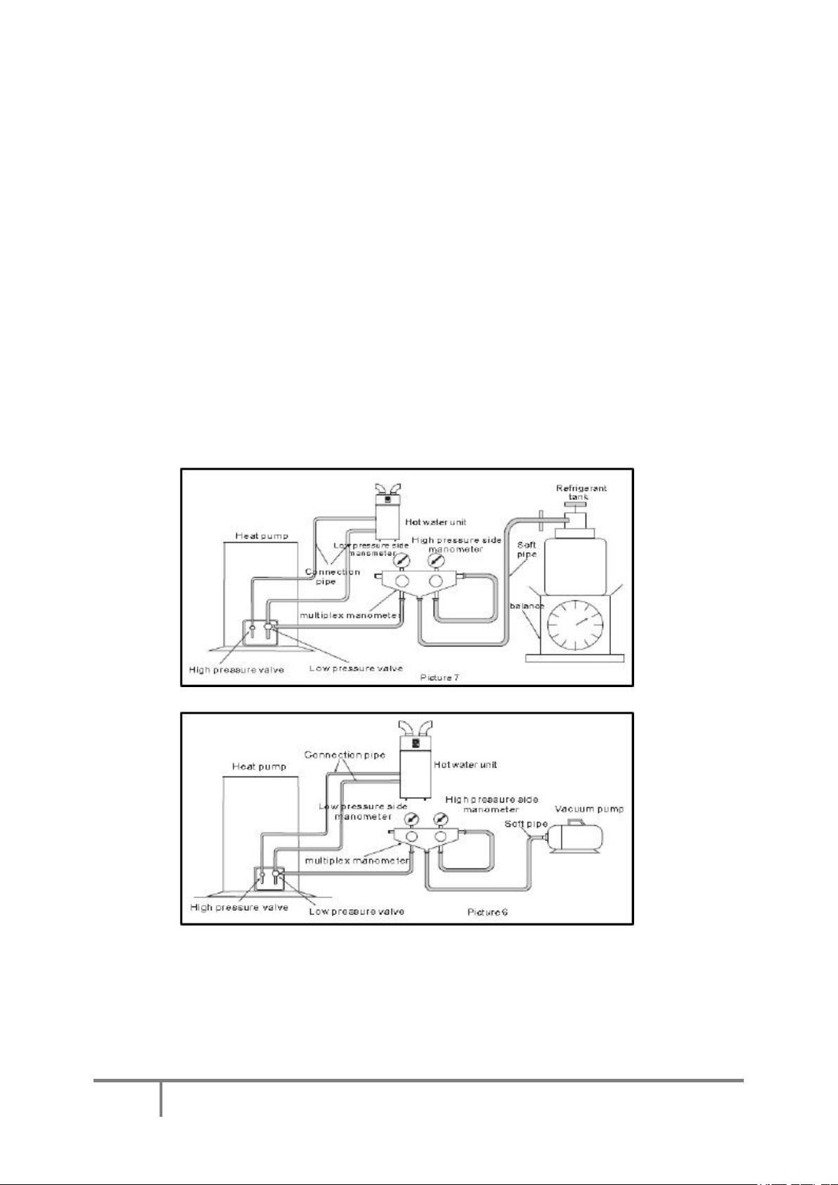
7.1 Vacuum and filling Refrigerants:
The unit is supplied pre-gassed. Should a refrigerant fill be required at any point, please note the following:
When you have finished the connection between the heat pump and the hot water unit, you must create a
vacuum in the hot water unit. See below pictures 6 & 7 below:
A. Unscrew the screw cap of the high pressure valve on the heat pump, and connect the multiplex
manometer to the check valve.
B. Connect the vacuum pump to the multiplex manometer, then open them to create a vacuum in the
hot water unit, making sure the absolute pressure is less than 70Pa, and lasts for 60 minutes.
C. When you have finished the vacuum test, open the check valve to let the refrigerant go into the
ASHP part of the unit.
D. When you need to add the refrigerant, please do so as follows:
NOTE: With the Ecocent, the ASHP and the cylinder are one unit and the above should be
interpreted accordingly.
Page 22

18of 36
ESP400-10-200L and 300L
7.2 Controller System Test:
Switch on the power to the unit, check the display of the controller – it will display the water temperature when
the unit is in standby mode. If the controller display is showing an incorrect reading or an error code, please
refer to Section 10.
7.3 Preparing for refrigerants:
a) On completing wiring of the unit, please release a little refrigerant from the low pressure side, or use
the vacuum pump to create the vacuum in the system, until the pressure is below 70Pa.
b) Once the unit is in vacuum, please open the high pressure valve and the low pressure valve until the
pressure is balanced, then check the joints for leaks.
c) Ducting—Please ensure that ducting is safely and appropriately fitted.
7.4 Insulation treatment:
As per the below picture, you must insulate all connecting pipes and you must use high quality, non flammable,
PVC insulating material, of 15mm-20mm thickness.
a) To keep the pipes in a tidy state, you may wrap the pipes together after being separately insulated.
b) Under no circumstances should you let electric wires come into contact with the plumbing.
7.5 Wiring:
All electrical wiring MUST be carried out by a competent electrician and be in accordance with the latest I.E.E.
Wiring Regulations. The wiring block diagram is set out below in diagram 14 and is the same for both 200L
and 300L units. Please see Appendix 1 for the layout of the PCBs.
Page 23

19of 36
ESP400-10-200L and 300L
Diagram 14. Great care should be taken to ensure that the unit is properly wired to the
mains electricity and any auxiliary components.
The mains wire connection will be found towards the top of the unit. The power supply
required is a standard 13A supply, unless a 3kW immersion heater is specified in which
case a 20A supply is required.
7.6 Earthing:
The unit MUST be earthed and a facility is provided for this in the unit Design. You must have the unit fitted by
a suitably qualified installer – ESP Accepts no responsibility for units that are not fitted by fully qualified
engineers Also, failure to have the unit fitted by a suitably qualified installer will invalidate the
warranty/guarantee of the unit.
7.7 Unit/System Controls:
The main control that is supplied with the unit is for viewing and altering system operating parameters. Other
controls will be necessary to control zone valves for solar or other auxiliary requirements.
7.8 Immersion Heater:
The unit is supplied with a 1.5kW immersion heater as standard. This can be used as an alternative and/or
complementary heat source and is used to raise the temperature of the stored water to a temperature above 60°C
once a week (automatically) to remove any risk from Legionella bacteria. The immersion heater is located
behind the black panel on the front of the unit.
Page 24

20of 36
ESP400-10-200L and 300L
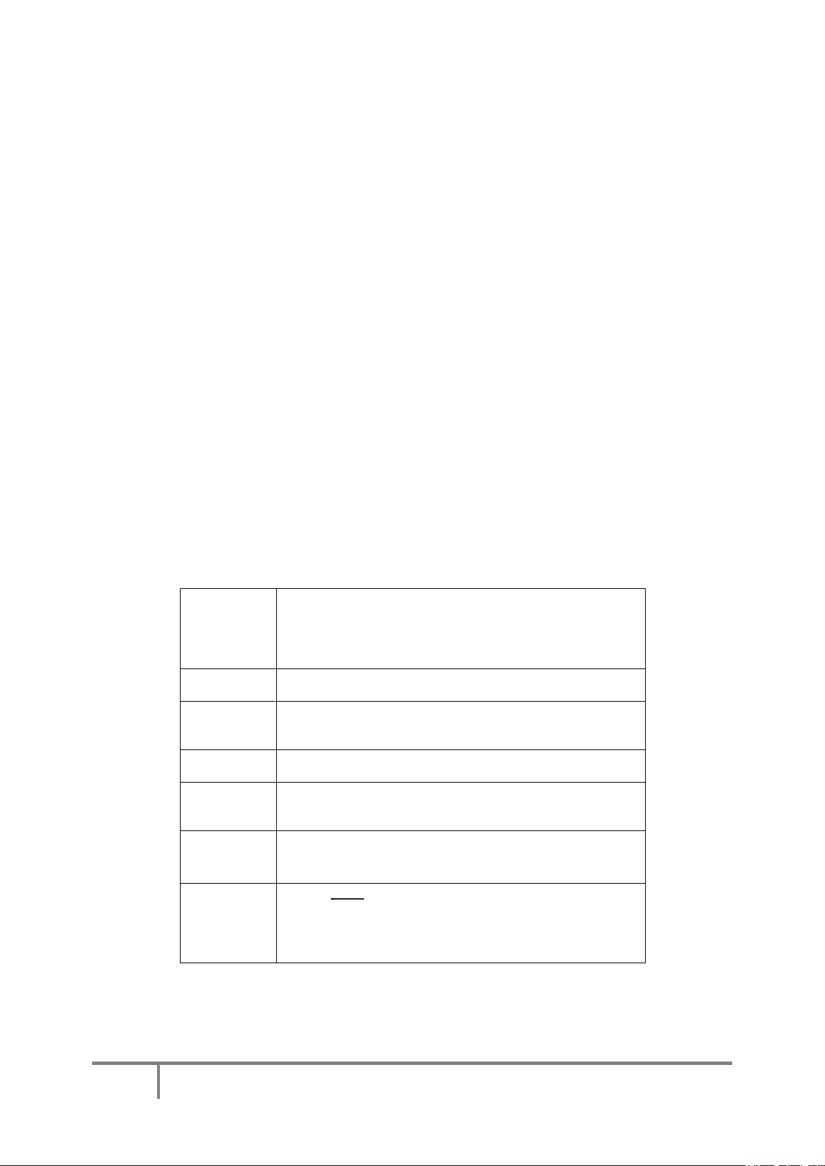
No.
Button Symbol
Name
Function
①
On/Off
Used to turn the unit on or
off and lock the control
②
Mode
Used to switch modes or save
parameters
③
Clock
Used to set the clock or
timers.
④
Electric
Heater
Used to turn the electric
heater on or off and to switch
fan modes.
⑤ Up
Used to move up or increase
parameter value.
⑥
Down
Used to move down or
decrease parameter value.
8.0 OPERATION
8.1 Control Panel Explanation:
Page 25

21of 36
ESP400-10-200L and 300L
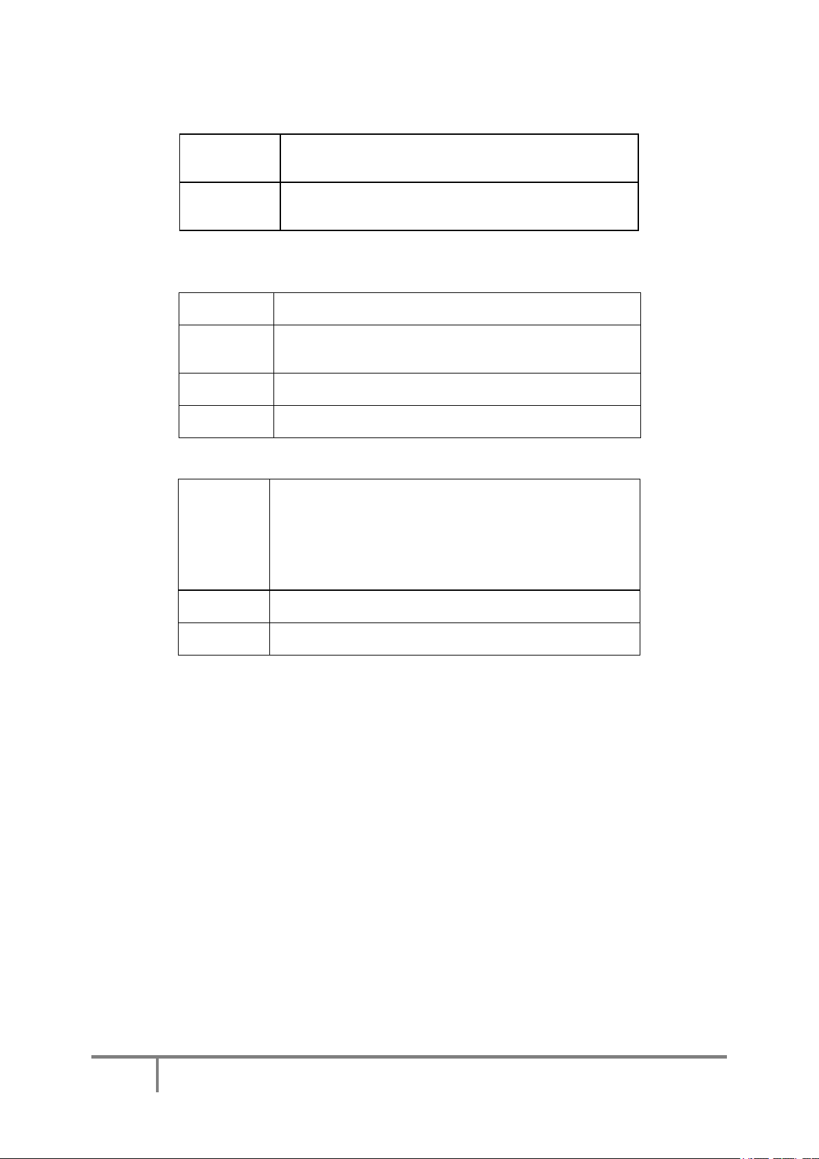
8.2 Display Explanation:
8.3 Using the control panel:
8.3.1 Turning the unit on or off:
Please note. Before the unit is turned on for the first time, you must:
1) Check that the tank is full of water;
2) Check that the unit is correctly wired in to the mains power from a suitable MCB.
When the power is turned on to the unit, the first screen is the start-up screen:
Page 26

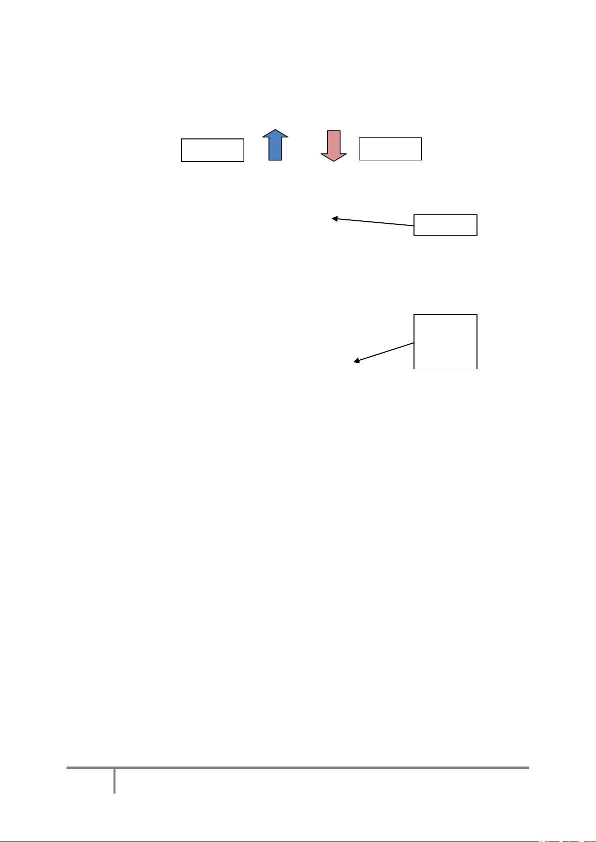
22of 36
ESP400-10-200L and 300L
Display when the unit
is running
Please note that the
version may be
different on your unit
Which then changes to show the firmware version:
The unit then displays the stand-by screen:
Press the on/off key for 0.5 second, the unit will beep and start and show the following screen:
Please note that the immersion heater symbol on later models has changed from that in the colour photos
to that in the diagram above.
In normal operation, the screen will be blank. Pressing the screen briefly in the area of the on/off button
will turn the screen on.
8.3.2 Mode selection:
The unit has seven modes: Standby, Heating, Eco Heating, Intelligent , Electric Heater, Fan and Vacation.
a) Standby Mode: The unit has power on to it but it is not set to heat.
b) Heating Mode: The water will be heated by ASHP. If the target temperature is not achieved by a
pre-programmed time (200 minutes), the immersion heater is switched on to accelerate the time taken
to reach the target temperature.
c) Eco Heating Mode: The water will be heated by ASHP only. This is normally used where the input
air temperature is higher.
d) Intelligent Mode: In this mode, the unit will heat the water by ASHP alone unless the input
temperature is too low, in which case the electrical heater is switched on.
e) Electric Heater Mode: Water is heated by immersion heater. This should only be used in the
unusual circumstance when the input temperature is very low.
Page 27

23of 36
ESP400-10-200L and 300L
f) Vacation Mode: You can set the unit to start up several months from the current date. When you go
on vacation, it allows you to set the unit to run at a preset date and time for your return.
Electric Heater mode and Fan modes are discussed further down.
Please note that the default mode is heating mode. If you are considering using any setting other than Heating,
Eco or Vacation mode, you are strongly advised to take advice from your installer.
To move between the modes, press the mode button repeatedly:
ATTENTION: When you have a vacation, set the unit to vacation mode and set a date for the unit to restart
before your return home so that hot water is available when you get home. Apart for keeping the unit frost free,
during your vacation the Ecocent will not run when set to “vacation mode”.
To check the target temperature, press the up or down button once and the target temperature will be displayed
in the main area of the screen.
To set the target temperature, press the up or down arrows when the unit is running. Once the desired
temperature is shown on the display, press the mode button once to confirm the setting. Pressing the on/off
button before the mode button will cancel the change and the target
temperature will revert to that previously set. Similarly, if, during the procedure, no button is pressed for 10
Secs, changes will be ignored and the unit will return to the previous settings.
Page 28

24of 36
ESP400-10-200L and 300L
8.3.3 Setting the Clock:
The clock can be set in either the standby or running modes. The following example illustrates the procedure
when in running mode:
Press the clock button once. The time will flash. Press the clock button again and the hour segment
will flash. Use the up or down buttons to adjust the hour as necessary then press the clock button to
confirm. The minute segment will then flash. Again, use the up or down buttons to adjust the minutes,
confirming by pressing the Clock button. The date will then flash. Press the clock button again and the
month segment will flash. Adjust as necessary using the same procedure then press the clock button to
confirm. The day segment then flashes and can be adjust. Pressing the clock button once more
confirms the date and the year will then start flashing. Press the clock button again to adjust the year,
confirming with the clock button. The display will revert to normal display:
Page 29

25of 36
ESP400-10-200L and 300L
8.3.4 Setting the timers.
In heating mode, Eco mode and intelligent mode, two timers can be set to define two periods of water heating.
However, setting the timers makes the Ecocent less economic to run.
Page 30

26of 36
ESP400-10-200L and 300L
To set the timers, press the clock button and hold it for 2 Secs. The “ON 1” symbol to the right of the main
display area will start flashing. Pressing the clock button again will cause the hour segment to flash. Adjust this
to the required time as if setting the clock (above). Once the minutes have been set, pressing the clock button
again will display the “OFF 1” symbol to the right of the screen. The time can be set as before. Pressing the
clock again will display the “ON 2” symbol to be displayed and the hours and minutes can be set as before.
Pressing the clock button to confirm the “OFF 2” minutes will save all settings and the display will revert to the
heating mode default screen. Up until that time, if no button is pressed for 5 Secs, the display will revert to the
default screen and the settings will not be saved. . To cancel the timers, press the on/off button for 2 Secs. Press
the on/off button to cancel the settings.
Page 31

27of 36
ESP400-10-200L and 300L
Page 32

28of 36
ESP400-10-200L and 300L
To cancel the timers:
8.3.5 Vacation Mode.
To set the vacation mode, first select vacation mode as described above then press and hold the clock button for
2 Secs. The “on” symbol and the date segment will flash in the main display area. Set the date as before.
Please see the following example:
Page 33

29of 36
ESP400-10-200L and 300L
8.3.6 Electric Heating Mode:
Warning. Using this mode will turn the immersion heater on in either standby or heater mode. Pressing the
Electric Heater button once will turn the immersion on and pressing it again will turn it off.
Page 34

30of 36
ESP400-10-200L and 300L
8.3.7 Fan mode settings.:
The fan mode can be used for two purposes: The fan speed in heating mode can be set or the fan can be set to
run even when the unit is in standby to provide additional ventilation.
Press and hold the electric heater button for 2 Secs. The fan mode symbol will change to (running)
which indicates that the fan will run at slow speed even when the target temperature is reached.
Pressing the same button for a further 2 Secs and the fan mode symbol will change to
(running) which indicates that the fan will run at high speed even when the temperature target has
been reached.
Pressing the button for a third time will cause the fan mode symbol to change once more to (Static)
which indicates that the fan will run at high speed only when there is a need for heating and until the target
temperature has been reached.
Pressing the button for a forth time will cause the fan mode symbol to change to (Static)
which indicates that the fan will run at slow speed only when there is a need for heating and until the target
temperature has been reached.
8.3.8 Locking the Keyboard:
To lock the keyboard, press and hold the on/off button for 5 Secs. Pressing it again for 5 Secs will unlock the
keyboard. When the keyboard is locked, the lock icon will be displayed in the bottom right corner of the main
display area.
8.3.9 Parameters;
The only parameter that can be set by the user is the target temperature which is set, by default to 55°C.
Page 35

31of 36
ESP400-10-200L and 300L
9.0 MAINTENANCE REQUIREMENTS
To ensure the continued optimum performance of the Ecocent, it should be regularly maintained. This is of
particular importance in hard water areas or where the water supply contains particulate matter. Maintenance
should be carried out by a suitably qualified plumber/engineer and any replacement parts used must only be
supplier recommended spare parts. It is recommended that maintenance is carried out every 12 months on the
cylinder and includes the checks detailed in this manual. If you are in a hard water area, you should check the
magnesium anode deterioration within 6 months of commissioning of the unit and annually 12 months after.
You will be able to see the rate at which deterioration is happening and set a date for a full inspection when it is
clear that a new magnesium anode is likely to be needed. Keeping a functioning magnesium anode is critical to
the longevity of the unit. If you run the unit without the anode you will invalidate the warranty/guarantee and
the stainless steel cylinder may be seriously damaged.
In hard water areas consideration should be given to periodically descaling the immersion heater elements. To
do this the unit will need to be drained; Paragraphs 9.3 to 9.5 below detail how to drain the unit and remove the
immersion heater(s).
Please check the condition of the sacrificial magnesium anode on any servicing/maintenance and fit a new
anode, if required.
9.1 Checking the Operation of Safety Valves:
Slowly open the Temperature and Pressure Relief Valve by twisting its cap for a few seconds. Check water is
discharged and that it flows freely through the tundish and discharge pipework. Check valve reseats correctly
when re-leased.
NOTE : The water discharged may be very hot. Repeat the procedure for the Expansion Relief Valve
(located on the Cold Water Combination Valve or Expansion Valve Core Unit).
9.2 Cleaning the Strainer:
The in-line strainer must be cleaned periodically by a suitably qualified engineer. The in-line strainer can be
found inside the cold water combination group valve on unvented systems or alternatively a Y strainer on open
vented systems. The engineer should:
i) Wash any particulate matter from the inline strainer under clean running water.
ii) Refit the inline strainer once totally clean or install a new one where necessary.
9.3 Draining the Unit:
Switch off the electrical supply to the unit. Turn off the mains water supply to the unit. Attach a hosepipe to the
drain cock having sufficient length to take water to a suitable discharge point below the level of the unit; at least
one metre below the unit is recommended. Open the hot water tap nearest to the unit to relieve the system
pressure. Open the drain cock. If water fails to drain from the unit, vent it by manually opening the
Temperature/ Pressure Relief Valve or “crack a joint” in the unit plumbing to prevent the creation of a vacuum
that may prevent effective draining.
9.4 Descaling the Immersion Heater:
Drain the unit. Open the cover to the immersion heater housing and disconnect wiring from immersion heater.
Remove the thermostat by carefully pulling out-wards from the immersion heater. Unscrew the immersion
heater backnut and remove the immersion heater from the unit. Over time, the immersion heater gasket may
become stuck to the mating surface. To break the seal insert a round bladed screwdriver into one of the pockets
on the immersion heater and gently lever up and down. Carefully remove any scale from the surface of the
element. DO NOT use a sharp implement as damage to the element surface could be caused. Ensure
sealing surfaces are clean and seals are undamaged; if in doubt fit a new gasket.
Replace immersion heater ensuring the lower (right angled) element hangs vertically downwards towards the
base of the unit. It may be helpful to support the immersion heater using a round bladed screwdriver inserted
into one of the thermostat pockets whilst the backnut is tightened. Replace the thermostat by carefully
plugging the two male spade terminations on the underside of the thermostat head into the corresponding
Page 36

32of 36
ESP400-10-200L and 300L
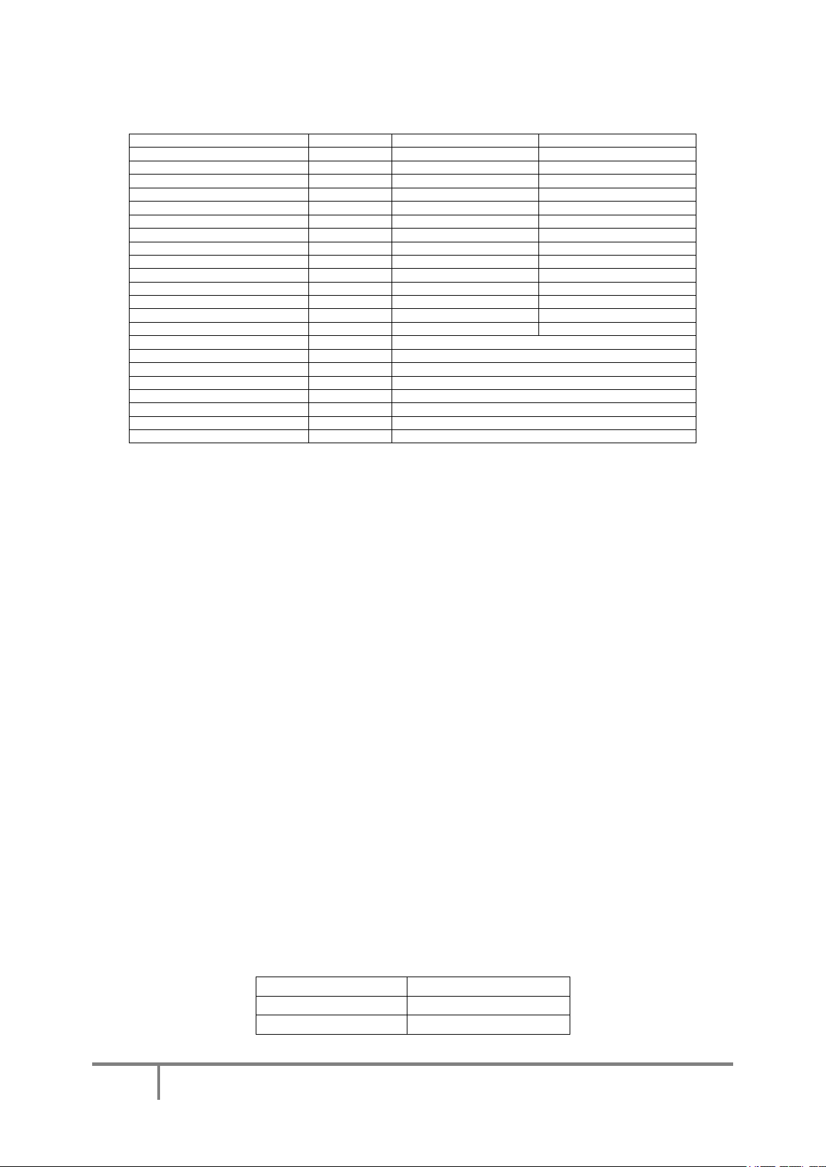
Malfunction
Display
Cause
Solution
Bottom water temp.
sensor failure.
PO1
Sensor is open or shortcircuit.
Check sensor and
change if necessary.
Top water temp
sensor failure.
P02
Sensor is open or shortcircuit.
Check sensor and
change if necessary.
Ambient temp
sensor failure.
P04
Sensor is open or shortcircuit.
Check sensor and
change if necessary.
Coil temp sensor
failure.
P05
Sensor is open or shortcircuit.
Check sensor and
change if necessary.
Refrigerant absorb
sensor failure.
P07
Sensor is open or shortcircuit.
Check sensor and
change if necessary.
Anti-freeze temp
senor failure.
P09
Sensor is open or shortcircuit.
Check sensor and
change if necessary.
Solar temp sensor
failure.
P034
Sensor is open or shortcircuit.
Check sensor and
change if necessary.
High pressure
protection.
E01
Exhaust pressure is too
high.
Check high pressure
switch and cooling
return circuit.
Low pressure
protection.
E02
Suction pressure is too low.
Check low pressure
switch and cooling
return circuit.
terminations on the element. Rewire the immersion heater. Close and secure terminal cover then the refill the
unit.
9.5 Refilling the System:
DO NOT switch on the immersion heater(s) or heat pump part of the unit until the system has been
completely refilled. Close the drain tap. With the hot tap open, turn on mains water supply.
When water flows from the hot tap allow to flow for a short while to purge air and to flush through any
disturbed particles. Close the hot tap and then open successive hot taps in system to purge any air. The
electrical supply can then be switched on.
9.6 Log Book:
Please complete the log book supplied with the Ecocent, stating what has been done, the date of the
service and the name/contact details of the servicing engineer.
9.7 Maintenance Requirements:
There are no formal annual maintenance requirements. However, it is advisable to check annually:
a) That the pressure and temperature relief valve is still functioning well by turning the plastic black
cap around to make sure that water comes out of the valve when the clack cap is turned.
b) Filters for debris.
c) That the air outlet to outside to make sure that it is clear from foliage, nests, etc.
Please note that the top cover of the Ecocent can be removed by a suitably qualified engineer/ plumber so that
the evaporator can be cleaned of dust and debris.
10.0 FAULTS
10.1 Simple Fault Finding
The following table is a list of simple faults and actions that can be taken to clear them. Diagnosis, testing and
repair should be carried out by a suitably qualified an experienced engineer/plumber.
Page 37

33of 36
ESP400-10-200L and 300L
Water flow
E03
Insufficient water in the
system.
Check water supply
is running freely and
of sufficient volume.
Electric Heater
overheat protection.
E04
Water flow volume
insufficient or the water
pressure is too low. See
also below.
Check water supply
is running freely and
of sufficient volume.
Anti freeze
protection.
E07
Water flow volume
insufficient or the water
pressure is too low.
Check water supply
is running freely and
of sufficient volume.
Communication
failure.
E08
Loss of signal from wired
controller to controller.
Check connections
between the
controller and PCB.
Winter frost
protection.
E09
Ambient temperature too
low.
10.2 Over heat protection
The unit is protected against the tank overheating. Should the tank temperature rise too high, the protector will
activate and isolate the power supply. Should the protector trip, it must be rest manually after the cause of over
heating has been fully investigated and corrected. The reset button is located behind the front panel (see section
5.2 above). Care should be taken to guard against the possibility of electric shock when re-setting the protector.
11.0 WARRANTY
11.1 Guarantee Terms
Should any factory fitted Temperature and/or Pressure Relief Valve(s) or other safety devices be tampered with
or removed or any recommended Temperature or Pressure Relief Valves/safety devices not be fitted, your
warranty/guarantee will be invalidated. Neither the Distributor nor
Manufacturer shall be responsible for any damage resulting from the tampering, howsoever caused, save where
such exclusion is unlawful.
ESP warrants/guarantees the electrical parts, thermal controls and valves relating to the cylinder for a period of
one year from the date of purchase, with the exception of normal wear and tear including any damage caused as
a result of lime scale deposits.
Page 38

34of 36
ESP400-10-200L and 300L
The stainless steel vessel forming part of the cylinder is warranted/guaranteed for a period of five years against
faulty manufacture or materials provided that:
i) It has been properly installed by a competent installer as per the instructions and recommendations
contained in this manual and all relevant Codes of Practice and Regulations in force at the time of
installation.
ii) Any disinfection has been carried out in accordance with BS 6700.
iii) It has not been modified in any way other than by ESP.
iv) It has only been used for the storage of wholesome water.
v) It has not been installed in a location liable to be subjected to frost, nor has
it been tampered with or been subjected to misuse or neglect.
vi) No factory fitted parts have been removed for unauthorised repair or replacement
vii) Within 45 days of purchase the user completes and returns the certificate supplied to register the
product.
The compressor in the heat pump is warranted/guaranteed for 2 years from the date of purchase.
Remaining parts of the heat pump are warranted/ guaranteed for 1 year from the date of purchase.
Evidence of purchase and date of supply must be submitted with any warranty/guarantee claim.
This warranty/guarantee is not valid for installations outside the United Kingdom or the Republic of Ireland.
Any warranty/guarantee is for replacement parts only.
The purchaser of the unit acknowledges that he/she has seen ESP’s conditions of supply and has understood
them.
All of our units are RoHS approved units.
This guarantee does not affect your statutory rights.
12.0 ENVIRONMENTAL INFORMATION
This product is made from many recyclable materials, therefore at the end of its useful life, it should be disposed of at a
Local Authority Recycling Centre in order to realise the full environmental benefits. The 1150 g of R410a gas contained
in the unit should be reclaimed, recycled or destroyed, in accordance with current Government regulations covering FGas available from WWW.Gov.UK and should only be attempted by a qualified technician
Please note:
The pace of product development is such that we reserve the right to change product specifications
without notice. We do, however, strive to ensure that all information in this leaflet is accurate at the time of
publication.
13.0 SPARE PARTS
Earth Save Products Limited carries spare parts for all the units it supplies. We strive to ensure that spare
parts are readily available at competitive prices. Should you need any spare parts and we will be pleased to give
you a quotation. Please call 00 44 (0)1865 598158.
Page 39

35of 36
ESP400-10-200L and 300L
Number
Components Name
1
Water Tank
2
Electronic Box Supporting Plate
3
Terminal Base
4
Wire Controller
5
Transformer
6
Main Controller
7
3uF Capacitor for Fan Motor
8
2uF Capacitor for Fan Motor
9
Protector Cover
10
Low Pressure Needle Valve (45mm)
11
Electric Heater 1.5kW
12
High Pressure Switch
13
Fixed Plate
14
Pull Rod
15
2-way valve
16
Thermostatic Expansion Valve
17
Strengthening Rod
18
Rubber Feet
19
Grille
20
Bottom Plate
21
Electronic Box Cover
22
Top Cover
23
Fan Motor
24
Protection Board
25
Fixed Plate
26
Compressor Capacitor
27
Compressor
28
Compressor Pull Rod
29
Evaporator
30
Electric Heater Cover
31
Decorated Front Plate
32
Connection Plate
13.1 Exploded diagram
The following diagram shows all of the parts of the Ecocent. The numbers correspond to the table below that
names all parts in case spares are ever required:
Page 40

36of 36
ESP400-10-200L and 300L
No.
Key
Definition of the Ports
1
OUT1
Compressor (Output)(220-230VAC)
2
OUT2
Heater (Output)(220-230VAC)
3
OUT3
Two Way Valve(Output)(220-230VAC)
4
OUT4
High Speed Fan(Output)(220-230VAC)
5
OUT 5
Low Speed Fan/Circulation Fan/Circulation Pump/Recovery Pump/Cooling
(Output)(220-230VAC)
6
AC-N
Ground
7
NET GND 12V
Remote Controller
8
DIO 1 GND
Remote ON/Off
9
DIO 2 GND
Over Heat Protection
10
DIO 3 GND
Low Pressure Protection
11
DIO 4 GND
High Pressure Protection
12
DIO 5 GND
(Spare)
13
DIO 6 GND
Flow Switch Protection
14
AIO1 GND
Ambient Temperature Sensor (input)
15
AIO2 GND
Bottom of Tank Sensor (Input)
16
AIO3 GND
Top of Tank Sensor (Input)
17
AIO4 GND
Coil Temperature Sensor/Anti-Freeze Sensor (Input)
18
AIO5 GND
Suction Temperature Sensor (Input)
19
AIO6 GND
Solar Temperature Sensor (Input)
20
CN6
Running Indication/Circulation Pump/Solar Pump
Appendix 1 – PCB Layouts
 Loading...