


8 C H A N N E L N E T W O R K A B LE C C T V S Y S T E M
W I T H I N T E G R A L 1 T B H A R D D R I V E
U S E R M A N U A L

SAFETY NOTICE
IMPORTANT PRECAUTIONS!
HIGH VOLTAGE HAZARD!
HIGH VOLTAGE INSIDE!
• Please keep this manual for later use.
• Please strictly comply with the warning indications on the machine and in this
book.
• Please abide by instructions when operating.
• Do not use accessory devices not recommended by the manufacturer. Incorrect
usage of accessory device may cause harm.
• Please use the power adapter equipped for th
power cord to the socket, please check if the specified requirements of the
adapter is in accordance with the local power supply network. Please contact
your dealer or the local power supply administration if you are not sure about
the power supply to be used.
• Do not place anything on or around the power cord. A damaged power cord may
cause electric shock.
• Pleas
• Before cleaning the machine, pull out the power plug and clean the machine
• Disconnect the unit from the mains power source if the unit is not likely to be
• Ensure air ventilation around the unit, and do not cover or block the vent hole.
• Do not place the unit in direct sunlight or near a heat source such as a heat
e do not touch any control parts not mentioned in the manual. Incorrect
adjustment of a control part not mentioned in the manual may damage the
machine.
with a slightly damp cloth. Do not use any liquid or sprayed cleaning agent.
used for a lon
radiator, heating equipment, or other objects that generate heat.
g period of time.
e unit. Before connecting the AC
2

Contents
Front panel layout . . . . . . . . . . . . . . . . . . . . . . . . . . . . . . . . . . . . . . . . . . . . . . . . . . 4
Rear panel layout . . . . . . . . . . . . . . . . . . . . . . . . . . . . . . . . . . . . . . . . . . . . . . . . . . . 5
Connection Diagram . . . . . . . . . . . . . . . . . . . . . . . . . . . . . . . . . . . . . . . . . . . . . . . . 5
Basic operations . . . . . . . . . . . . . . . . . . . . . . . . . . . . . . . . . . . . . . . . . . . . . . . . . . . . 6
To Access the Menu . . . . . . . . . . . . . . . . . . . . . . . . . . . . . . . . . . . . . . . . . . . . . . . . . 7
Making a Recording . . . . . . . . . . . . . . . . . . . . . . . . . . . . . . . . . . . . . . . . . . . . . . . . . 8
Playing Back a Recording . . . . . . . . . . . . . . . . . . . . . . . . . . . . . . . . . . . . . . . . . . 10
Transfering a Recording to USB . . . . . . . . . . . . . . . . . . . . . . . . . . . . . . . . . . . . . 10
Main Menu Layout . . . . . . . . . . . . . . . . . . . . . . . . . . . . . . . . . . . . . . . . . . . . . . . . . 11
Remote Viewing . . . . . . . . . . . . . . . . . . . . . . . . . . . . . . . . . . . . . . . . . . . . . . . . . . 14
Trouble shooting . . . . . . . . . . . . . . . . . . . . . . . . . . . . . . . . . . . . . . . . . . . . . . . . . . 17
This manual is designed to be used as a quick start guide alongside the informative
general user interface (GUI) of the DVR. Additional details of the subjects covered
ay be found within the on-screen menus of the machine itself. The menu above is
m
not exhaustive and is designed to lead the user quickly to the most often required
aspects of the unit.
The DVR will require a connection to a monitor to be programmed.
3
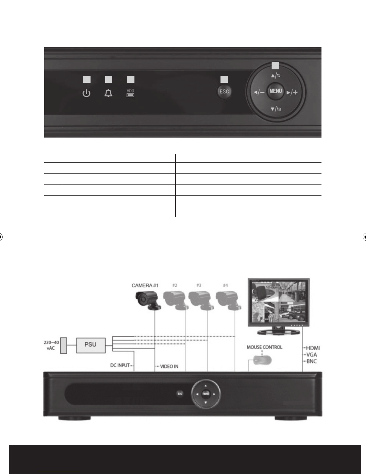
Front Panel
5
1 2 3
No. FUNCTION LED COLOUR
1 Main power on Blue
2 Alarm Indication Blue
3 HDD/Record Indication Blue
4 Escape N/A
5 Navigation keys for Menu N/A
4
Connection Diagram
4
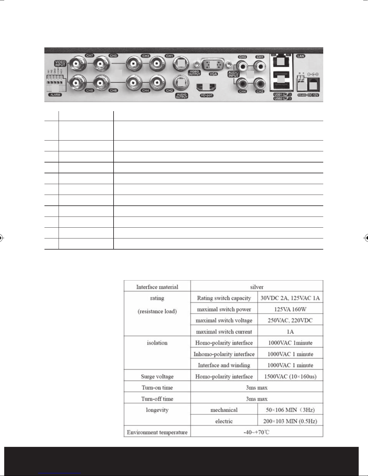
Rear Panel
3
2
4
1
5
7
6
No. interface ID Description
1 ALARM Switch alarm output (normally open contact)
INPUT/OUTPUT External devices require a power supply
2 VIDEO-IN Video input BNC connectors x 8
3 VIDEO-OUT Video output BNC
4 AUDIO-OUT Audio output AV
5 VGA VGA display output
6 HDMI HDMI display output
7 AUDIO-IN Audio input AV x 4
8 NET/LAN Network Interface
9 USB USB interface x 2
10 RS485 RS485 Interface
8
9
10 11
11 DC-12V 12V Power Input from power supply
NB. To obtain the best quality on screen display it is highly recommended to
connect a monitor via the HDMI output.
In order to avoid
damage when using
the alarm inputs/
outputs please refer
to relay parameter list:
5

Basic operations
POWER ON
Plug the red lead from the 5-way power supply marked DVR into the 12VDC power
supply input on the DVR. Turn on the DVR at the mains power point. The Power
supply indicator light (Blue) will illuminate on the DVR front panel followed by several
short bleeps.
POWER OFF
Turn off the DVR at the mains power source.
Notes on power
1. Auto resume after power failure. If the DVR is shut
automatically backup video and resume previous working status after the power is
restored.
2. Replacing the hard disk. Before replacing the hard disk, the power to the DVR must
be turned off.
3. Replacing the battery. Before replacing the battery, the power supply must be turned
off. The system time must be checked regularly. If the time is not correct you must
replace the b
same battery type.
4. Do not power off the DVR by removing the power cord from the unit.
5. Do not power off during recording.
MOUSE CONNECTION
In order to prevent un-authorised tampering, most functions of the DVR are mouse
controlled. Please plug in the supplied mouse via the USB interface on the rear panel
when operating the DVR.
VE VIEWING
LI
On start up the DVR will display a quad (four channel) image. Using the Mouse Control,
double click on any image to bring to full screen. Double click again to return to a quad
screen.
attery. It is recommended replacing the battery every year using the
down abnormally, the DVR can
System time and date, channel name, recording status and alarm status are indicated
by the following icons:
Recording status
Motion detect
Video loss
Camera lock
6
 Loading...