

Installation and User Guide
DIGI-VIEW 4 SYSTEM

Regulatory
FCC Certification
This equipment has been tested and found to comp ly w ith the limits for
a class A digital device, pursuant to Part 15 of the FCC rules. These
limits are designed to provide reasonable protection against harmful
interference when the equipment is operated in a commercial
environment. This equipment generates, uses, and can radiate radio
frequency energy and, if not installed and used in accordance with the
instruction manual, may cause harmful interference to radio
communications. Operation of this equipment in a residential area is
likely to cause harmful interference in which case the user will be
required to correct the interference a their own expense.
CE Mark
This product is marked with the CE symbol and indicates compliance
with all applicable EEC directives.

System Introduction ---------------------------------------------------------------- 1
Package Content --------------------------------------------------------------------2
DVR Front Panel Buttons ------------------------------ --------------------------- 3
DVR Back Panel Buttons -------------------------------------------------------- 4
Video Output Connection (To TV/Monitor) ----------------------------------- 5
Video Input Connection (Camera) --------------------------------------------- 6
Sensor I nstallation ----------------------------------------------------------------- 7
Alarm Installation ------------------------------------------------------------------- 8
Switch on th e DVR ----------------------------------------------------------------- 9
Record -------------------------------------------------------------------------------- 10
OSD Operation Guide:Play Menu --------------------------------------------- 11
OSD Operation Guide:Main Menu --------------------------------- ---------- 12
OSD Operation Guid e: Cam era Select ---------------------------------------- 12
OSD Operation Gui d e: Re c ord S el e ct -------------------------------------------13
OSD Operation Gui d e: Re c ord Mod e ------------------------------------------- 13
OSD Operation Gui d e: Fram e Ra t e ----------------------------------------------13
OSD Operation Guide: Video Quality --------------------------------------------13
OSD Operation Guide: Schedule Record -------------------------------------- 14
OSD Operation Guide: Sub Menu ----------------------------------------------- 15
OSD Operation Guide: Change Password ------------------------------------ 15
OSD Operation Gui d e: Time S et u p --------------------------------------------- 16
OSD Operation Guide: Buzzer Setup ------------------------------------------- 16
OSD Operation Gui d e: Auto Record Setup ------------------------------------ 16
OSD Operation Gui d e: A u di o Re c ord Setup ----------------------------------- 16
OSD Operation Guide : A udi o Mut e ---------------------------------------------- 17
OSD Operation Guide: Audio Channel Select -------------------------------- 17
Hard Drive Set Up ------------------------------------------------------------------- 18
CONTENTS

OSD Operation Gui d e: O ver Write ------------------------------------------------- 18
OSD Operation Guide: HDD Size and HDD used ------------------------------ 18
OSD Operation Guide: HDD Format ---------------------------------------------- 18
OSD Operation Guide: Sensor Setup Menu ------------------------------------- 19
OSD Operation Guide: Motion Setup Menu -------------------------------------- 20
How to backup through USB to PC ------------------------------------------------- 21
Print Event ------------------------------------------------------------------------------- 23
DVR Specification --------------------------------------------------------------------- 24
Camera Specification ----------------------------------------------------------------- 25
System Illustration --------------------------------------------------------------------- 26

DIGI-VIEW 4 SYSTEM is a CCTV surveillance system for home
and small office uses. Connecting four cameras to DVR (Digital
Video Recorder), you can enjoy various functions DVR provides.
The Digital Video Recorder (DVR) is for recording / retrieving
video streams up to 4 channels at the same time. It adapts a
digital image compression technology to compress the input
channel video streams, and uses a HDD (Hard Disk Drive) to
record the compressed video stream.
SYSTEM INTRODUCTION
Plug & Play
One Power System
Installation
Four Pictures in One Screen for monitoring
OSD Operation
Record in HDD / Schedule Record
Playback ( 1x, 2x, 4x, 8x, 32x, 64x);Reverse Play (1 x)
Motion Detection
USB Data Transfer
Functions
(Built-in DVR)
The DIGI-VIEW 4 SYSTEM contains CCTV cameras which are
capable of Indoor & Outdoor (WATERPROOF) Use and
Day & Night use (Built-in IR LED)
Camera
Video Output Connection to TV / Monitor
Video Input Connection for CCTV Cameras
USB:Download Pictures to PC / Laptop
Advance User:Sensor / Alarm Installation
System

Package Content
DIGI-VIEW 4 CHANNEL DVR * 1
DVR POWER TRANSFORMER *1
DAY & NIGHT WEATHERPROOF CAMERA * 4
15 METER DIY CABLE * 4
50 cm DVR TO TV LEAD (BNC TO BNC) * 1
50 cm DVR TO TV LEAD (BNC TO RCA) *1
BNC TO RCA ADAPTOR * 1
CD DSIK * 1
MANUAL BOOK * 1
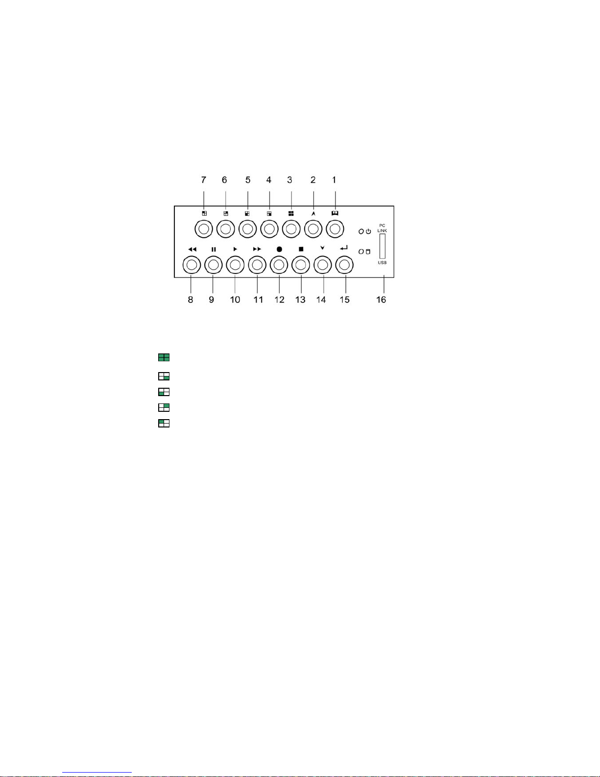
DVR Front Panel Buttons
1. Menu button:Press to display Operation menu option
2. 2. Up button:used in menu
3. All channels button:Press to display all channels
4. Channel 4 button:Press to display channel 4
5. Channel 3 button:Press to display channel 3
6. Channel 2 button:Press to display channel 2
7. Channel 1 button:Press to display channel 1
8. Reverse : Press to rewind playback
9. Pause button:Press to pause playback
10. Playback button:Press to start playback
11. Fast forward button:Press to play the recorded stream faster
12. Recording button: Press to start recording
13. Stop Recording / Stop Playback button:Press to stop recording
or playback .The authorized password is requested upon stopping
recording .Default password is 111111.
14. Down button : Used in menu
15. Select button:Change the setting value or enter into a sub menu
16. USB Link Port
f
z
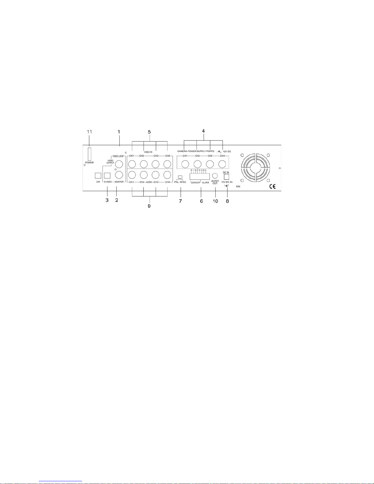
DVR Back Panel Functions
1. VIDEO Output (BNC ONE) to TV / Monitor
2. VIDEO Output (BNC TWO)
3. S-Video Output
4. Camera Power Supply (To Camera)
5. Video Input (For Camera)
6. Sensor / Alarm Input
7. Video Format Switch (NTSC / PAL)
8. DVR Power In (DC- in, 12 volts, 4.0A)
9. AUDIO INPUT
10. AUDIO OUTPUT
11. Power Switch
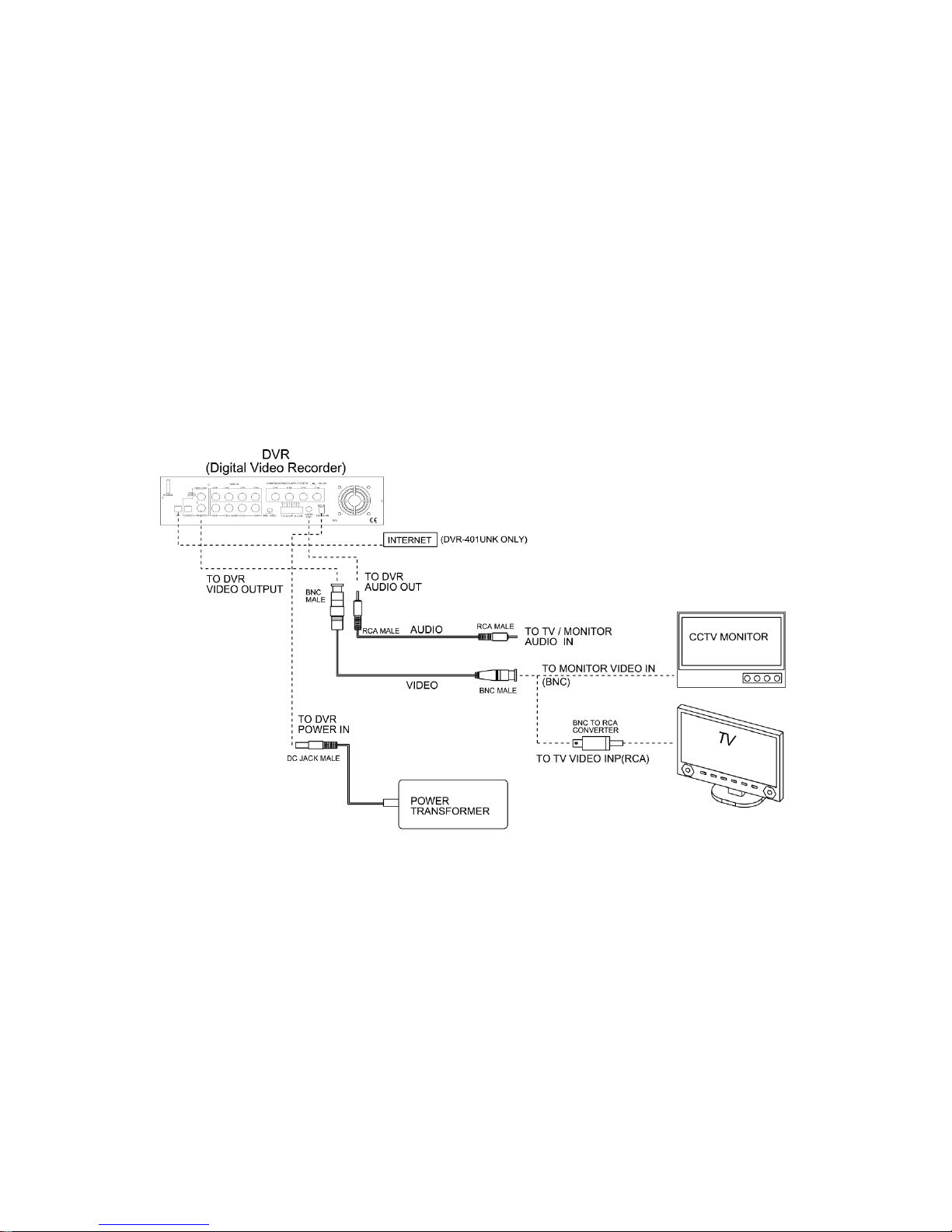
Video Output Connection ( TV or Monitor)
Connect a TV (Monitor) to the DVR using one of the video output connectors.
The DVR provides 1 x S-Video and 2 x BNC vi deo outputs.
The below figure shows the video line c onnection.
WHAT’S BNC => IT’S CONNECTOR FOR YOUR CABLE TV INPUT IN T V.
WHAT’S RCA => IT’S CONNECTOR FOR YOUR VCR / PS2 INPUT IN TV.

Video Input Connection (Camera)
Connect cameras to the DVR. The DVR provides 4 x BNC connectors.
The camera installation procedure is shown below:
I. Connect the video signal line and power to the DVR.
II. Connect the video signal line and power to cam e ra.
 Loading...