

Page 1
USER MANUAL
www.espuk.com
EZTAG3 | PROXIMITY AND KEYPAD DOOR ENTRY
EZTAG3 Manual_Layout 1.indd 1 18/11/2016 15:28:04
Page 2
2
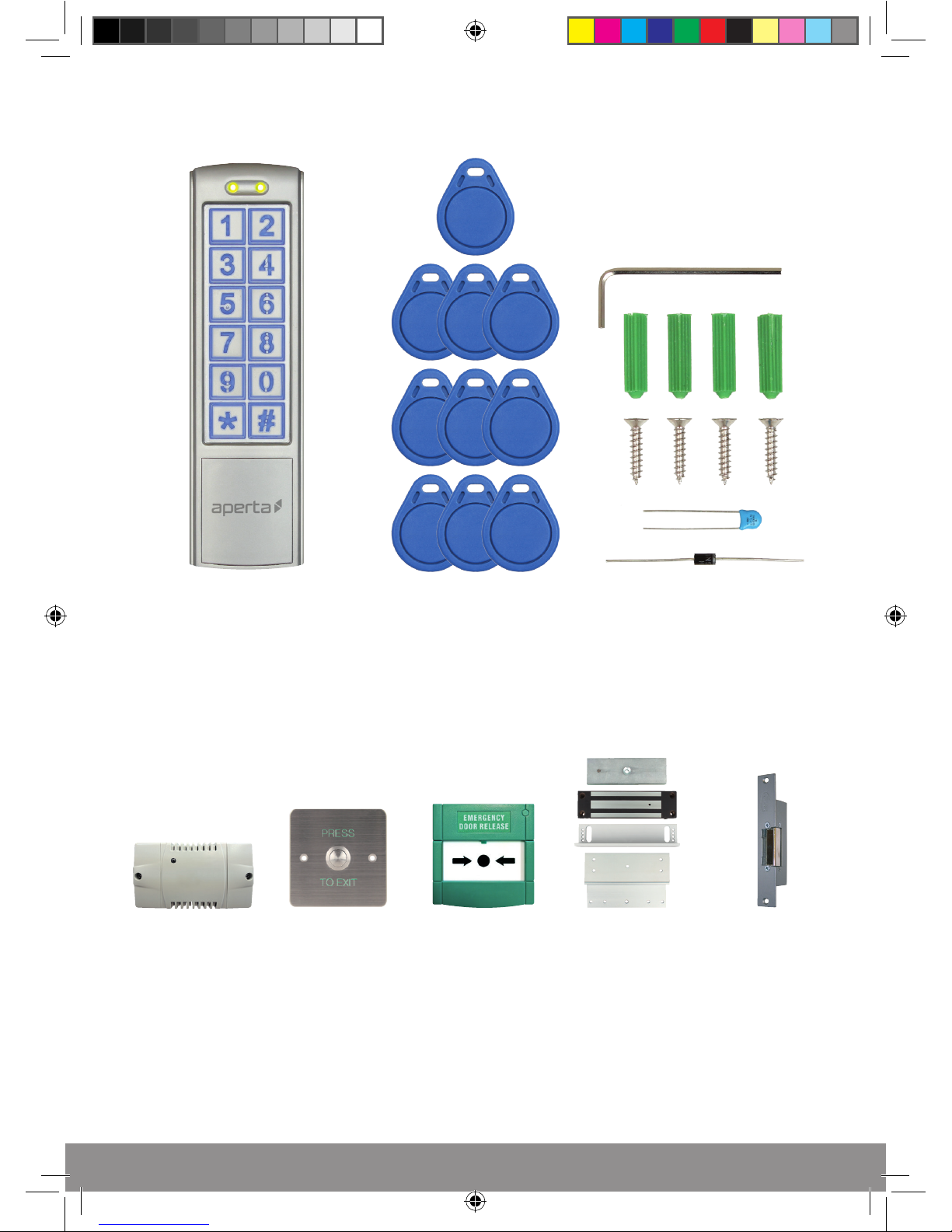
System Components
Proximity and Keypad Reader 10 x Proximity Tags 1 x Hex Key
4 x Plastic wall plug
4 x Countersunk screws
1 x Diode and 1 x Capacitor
Optional Accessories
EVBPSBB
Lock Power Supply
EV-EXIT
Push to Release
EV-EBG
Emergency Release
EV-ML-250/500XT
Electro-magnetic Lock
ENTERD
Electric Lock
EZTAG3 Manual_Layout 1.indd 2 18/11/2016 15:28:07
Page 3

3
Contents
Installation .................................................. 4
EZTAG3 Wiring Example 1 ..................................... 5
EZTAG3 Wiring Example 2 ..................................... 5
Advanced Programming Guide
How to set-up Access Pin Number ........................ 6
How to set-up Access Tags ............................... 6
Deleting Access Pin or Tag ................................ 7
Changing Programming Pin ............................... 7
Clear all Pin and Tag Data ................................ 8
Default to Factory Settings ................................ 8
Lock 1 Output Operating Time ............................. 9
Enable ‘Door Bell’ Facility ................................. 9
Enable ‘Tamper Alarm’ facility ............................ 10
Access Pin Number for Lock 2 Output ..................... 10
Deleting Access Pin for Lock 2 ............................ 11
Lock Output Operating Time for Lock 2 Output .............. 11
System setup record ......................................... 12
User Guide .................................................. 14
Technical Specification ....................................... 14
EZTAG3 Manual_Layout 1.indd 3 18/11/2016 15:28:07
Page 4
4
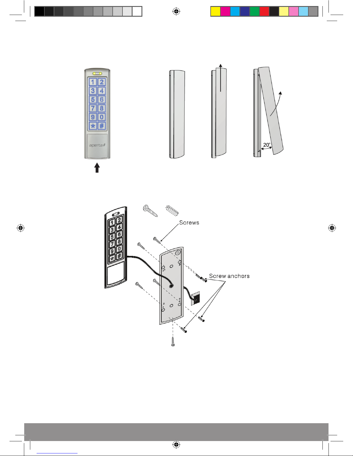
Installation
Note: if using more than one keypad, ensure that the keypads are mounted a minimum 185cm apart
(Side View)
Push the keypad up to release from mount plate
Release hex screw from
the bottom of the keypad
Thread system cable through the cable entry hole then make
the system connections (as per the wiring diagram), mount the
bracket to the surface and slide the keypad to the mountplate,
re-fit the hex screw to secure into position.
EZTAG3 Manual_Layout 1.indd 4 18/11/2016 15:28:07
Page 5
5
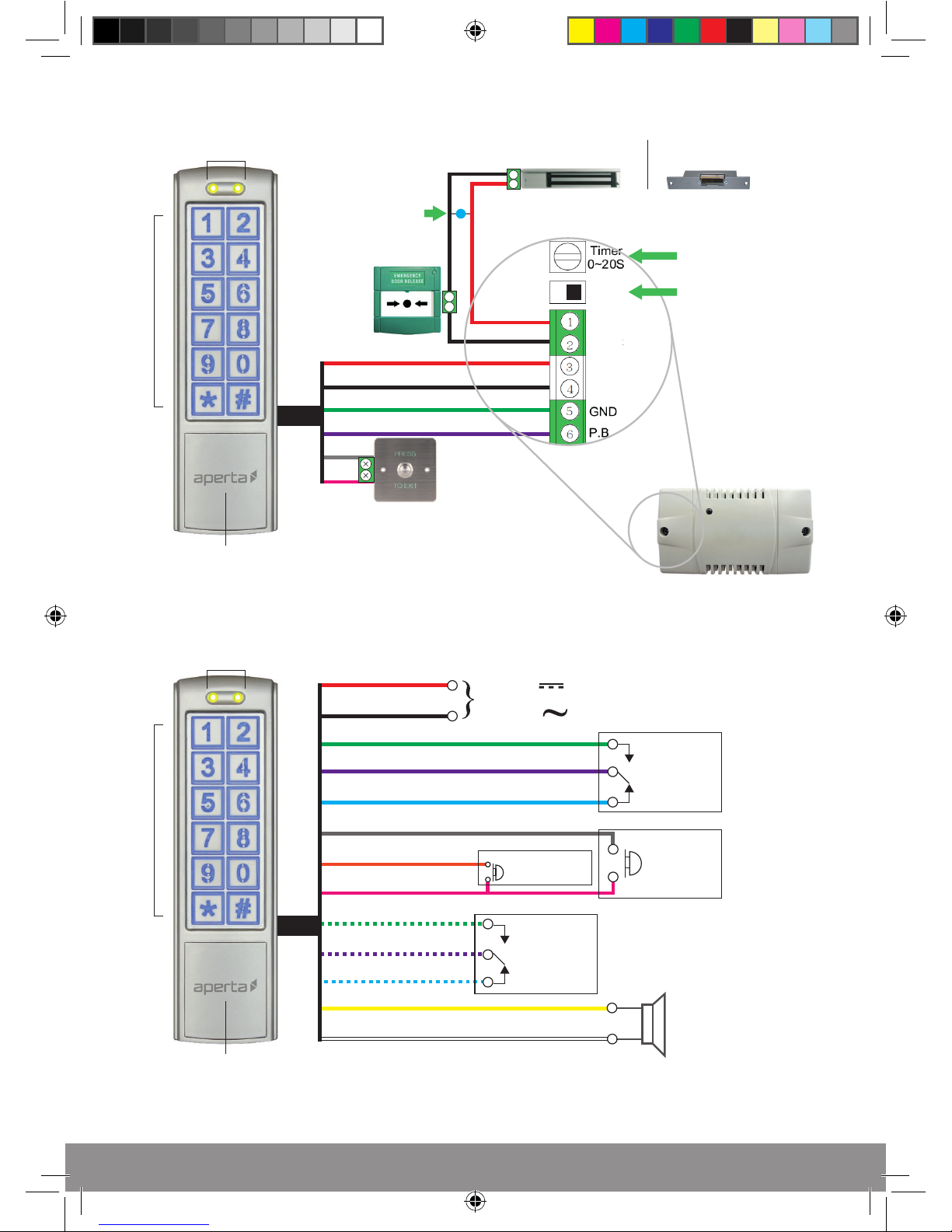
EZTAG3 Wiring Example 1
4
3
+
+
+
_
_
_
Red
NC
Black
Green
Purple
Grey
Pink
Electro-magnetic lock Electronic lock
Tag Reader
Indication LEDs
Keypad
Tag Reader
Indication LEDs
Keypad
EZTAG3 Wiring Example 2
Red
Black
Green/White
Purple/White
Yellow
White
Blue/White
Output for
Lock 2
(Volt-free)
N.O
COM
N.C
Speaker connection
for ‘door bell’ facility
(8Ω 0.5w recommended)
Input DC:
+12V - +24V
Input AC:
12V - 24V
or
+
_
Grey
Orange
Pink
Push button
for Lock 1
(N.O)
P.b for Lock 2
(N.O)
Green
Purple
Blue
Output for
Lock 1
(Volt-free)
N.O
COM
N.C
Lock -release time
N.C for
Electro-magnetic lock
N.O for
Electronic lock
Capacitor for
Electro-magnetic lock
Diode for
Electronic Lock
EZTAG3 Manual_Layout 1.indd 5 18/11/2016 15:28:09
Page 6

6
How to set-up Access Pin Number
Action
Step
Number
Keypad
Indication
9
0 2
? ? ? ?
Long
Tone
# #
1
2
3
4
5
6
Long
Tone
Double
Tone
Long
Tone
Enter a 4 digit pin
(1234 not be used)
To end programming
0 0
0
9 9
9
Enter a starting
location number
Enter
Programming
1 2 3 4 1 2 3 4
(Default)
How to set-up Access Tags
Action
Step
Number
Keypad
Indication
9
0 5
Long
Tone
# #
1
2
3
4
5
6
Long
Tone
Long
Tone
Tone
? ? ?
7
Tone
To end
programming
0 0
0
9 9
9
Enter a unused
location number*
Enter
Programming
Enter number of
tags to be registered
*Each tag will use up a location number
1 2 3 4 1 2 3 4
(Default)
Present the tag with the
lowest serial number
All other batch tags
will auto register
EZTAG3 Manual_Layout 1.indd 6 18/11/2016 15:28:09
Page 7

7
Changing Programming Pin
Action
Step
Number
Keypad
Indication
3
Long
Tone
# #
1
2
3
4
5
Long
Tone
To end programming
Enter
Programming
? ? ? ?
Enter new 4 digit
programming pin
? ? ? ?
Re-enter new 4 digit
programming pin
1 2 3 4 1 2 3 4
(Default)
Note; To access keypad’s programming mode, the 4 digit
programming code is entered in twice
Deleting Access Pin or Tag
Action
Step
Number
Keypad
Indication
Long
Tone
1
2
3
4
0 0
0
9 9
9
Enter the location
number of tag/pin
Enter
Programming
1 2 3 4 1 2 3 4
(Default)
To delete
# #
To end programming
EZTAG3 Manual_Layout 1.indd 7 18/11/2016 15:28:09
Page 8

8
Clear all Pin and Tag Data
Action
Step
Number
Keypad
Indication
8
8 8
Long
Tone
# #
1
2
3
4
Long
Tone
To end programming
Enter
Programming
1 2 3 4 1 2 3 4
(Default)
Default to Factory Settings
Action
Step
Number
Keypad
Indication
8
9 9
Long
Tone
# #
1
2
3
4
Long
Tone
To end programming
Enter
Programming
1 2 3 4 1 2 3 4
(Default)
EZTAG3 Manual_Layout 1.indd 8 18/11/2016 15:28:09
Page 9

9
Enable ‘Door Bell’ Facility
Action
Step
Number
Keypad
Indication
2
Long
Tone
# #
1
2
3
4
Long
Tone
To end programming
Enter
Programming
0 2
To enable
Becomes the ‘door bell’ push in normal mode
1 2 3 4 1 2 3 4
(Default)
0 1
To disable
Lock 1 Output Operating Time
Action
Step
Number
Keypad
Indication
1
Long
Tone
# #
1
2
3
4
Long
Tone
To end programming
Enter
Programming
Enter number
of seconds 00-99
? ?
1 2 3 4 1 2 3 4
(Default)
EZTAG3 Manual_Layout 1.indd 9 18/11/2016 15:28:09
Page 10

10
Access Pin Number for Lock 2 Output
Action
Step
Number
Keypad
Indication
9
0 3
? ? ? ?
Long
Tone
# #
1
2
3
4
5
6
Long
Tone
Double
Tone
Long
Tone
Enter a 4 digit pin
(1234 should not be used)
To end programming
0 0
Enter an unused
location number
Enter
Programming
1 2 3 4 1 2 3 4
(Default)
0 9
Enable ‘Tamper Alarm’ facility
Action
Step
Number
Keypad
Indication
6
Long
Tone
# #
1
2
3
4
Long
Tone
To end programming
Enter
Programming
0 2
To enable
Tamper alarm activates the keypad’s internal buzzer and
‘door bell’ output if the light sensor is exposed
1 2 3 4 1 2 3 4
(Default)
0 1
To disable
EZTAG3 Manual_Layout 1.indd 10 18/11/2016 15:28:09
Page 11

11
Lock Output Operating Time for Lock 2 Output
Action
Step
Number
Keypad
Indication
5
Long
Tone
# #
1
2
3
4
Long
Tone
To end programming
Enter
Programming
Enter number
of seconds 00-99
? ?
1 2 3 4 1 2 3 4
(Default)
Deleting Access Pin for Lock 2
Action
Step
Number
Keypad
Indication
1
2
3
4
Enter the location
number of pin
Enter
Programming
1 2 3 4 1 2 3 4
(Default)
To delete
# #
To end programming
0 0
0 9
4
5
Long
Tone
EZTAG3 Manual_Layout 1.indd 11 18/11/2016 15:28:10
Page 12

12
To assist in future programming, it is recommended that a
record is made of the system setup.
System Location Tag Serial
Tag Owner Notes
Number (000-999) Number
EZTAG3 Manual_Layout 1.indd 12 18/11/2016 15:28:10
Page 13

13
System Location Tag Serial
Tag Owner Notes
Number (000-999) Number
EZTAG3 Manual_Layout 1.indd 13 18/11/2016 15:28:10
Page 14

14
To access programming mode To release Lock 1
(A)
Enter a programmed
Access Pin number
(B)
Present a
registered tag
1 2 3 4 1 2 3 4
(Default)
User Guide
Technical Specification
DC input 12 - 24volts
AC input 12 - 24volts
Standby current 80ma
Operating current (without lock) 110ma
Working temperature -20c to +50c
Reader frequency 125KHz
IP rating 65
Dimension 150 x 44 x 24mm
EZTAG3 Manual_Layout 1.indd 14 18/11/2016 15:28:10
Page 15

15
EZTAG3 Manual_Layout 1.indd 15 18/11/2016 15:28:10
Page 16

www.espuk.com
Elite Security Products
Unit 7, Target Park, Shawbank Rd
Lakeside, Redditch B98 8YN
Telephone: 01527 51 51 50
Fax: 01527 51 51 43
email: info@espuk.com
K16
EZTAG3 Manual_Layout 1.indd 16 18/11/2016 15:28:10
 Loading...