

Page 1

APWIFIDS │WI-FI DOOR STATION
www.espuk.com
J2474 ESP Instruction Manual APWIFIDS.indd 1 15/03/2017 11:20:14
Page 2
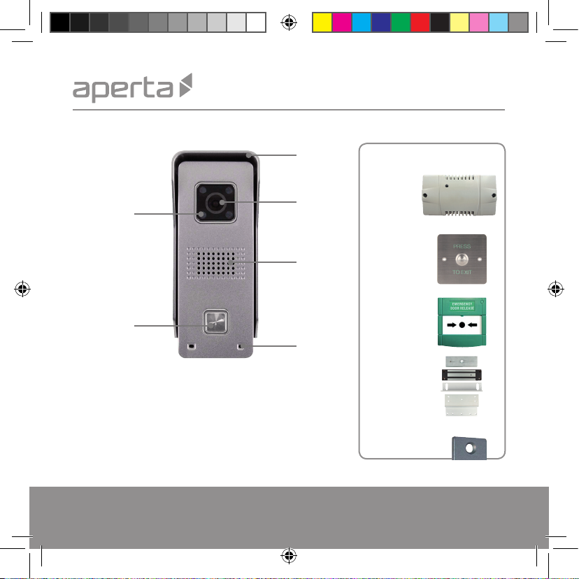
System Overview
IR LED
Sunshield
Camera lens
Optional accessories:
EVBPSBB
Lock power
supply
Speaker
Call button
EV-EXIT
Push to release
EV-EBG
Emergency release
Microphone
Kit contains:
■ Wifi door station
■ 12vDC (500mA) power supply
■ 10DB Wifi Antenna
■ Micro SD card (pre-installed)
■ Hex key
■ Reset pin tool
■ LAN terminal
■ Wire connectors
■ Screws and rawl plugs
EV-ML-250/500XT
Electro-magnetic lock
ENTERD
Electric lock
Page 2
J2474 ESP Instruction Manual APWIFIDS.indd 2 15/03/2017 11:20:15
Page 3

Connections
It is recommended the door station is programmed prior to installation.
Rear of door
station
Red
Black
+
Input 12vDC 500mA
-
Antenna
Purple
Yellow
White
Grey
Orange
Orange & White
Green
Green & White
J2474 ESP Instruction Manual APWIFIDS.indd 3 15/03/2017 11:20:15
N.O
COM
N.O
COM
Output for lock
(Volt-free)
Output for
doorbell
(Volt-free)
LAN
connection
(Not required
for Wifi use)
*See advanced
settings
Page 3
Page 4

Installation
90
。
1.2 m1 .5 m~
Page 4
Site the door station 1.5 meters from the ground,
or to suit application.
Position camera in the direction of where a visitor
will stand during operation.
Avoid areas of high sunlight and noise levels.
Surface mount the sunshield of the door station and
connect the system cabling.
Mount the camera to the sunsheild by fixing with
the supplied hex screw.
All system connections are to be made inside the building,
this includes the siting of the antenna.
J2474 ESP Instruction Manual APWIFIDS.indd 4 15/03/2017 11:20:15
Page 5

System set up
Please ensure the following;
1. The user’s smart-phone is connected to the Wi-Fi network.
2. The Door Station is within the network’s Wi-Fi range.
3. The network’s key/password is avaliable.
Whilst the door station is powered, the rear
tamper switch will be active. Ensure the tamper
switch is surpressed during setup.
If the tamper alert is activated the alarm will
sound for 60 seconds, or bypassed by powering
down for 10 seconds
Tamper switch
Rear of door
station
Page 5
J2474 ESP Instruction Manual APWIFIDS.indd 5 15/03/2017 11:20:15
Page 6
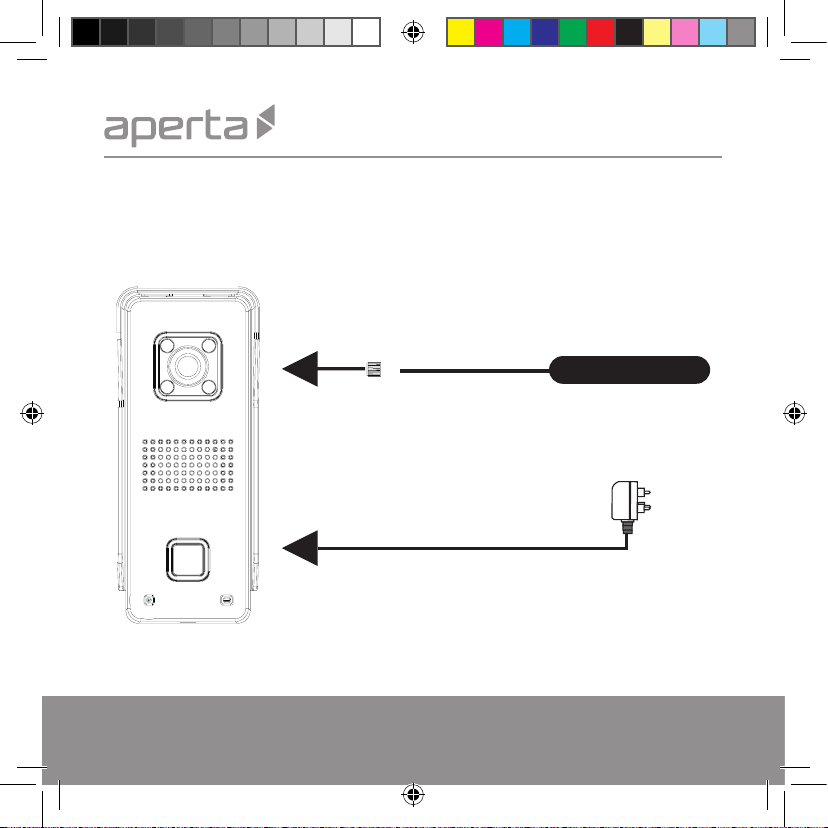
Step One:
Connect the Antenna and power supply to the door station. Apply power.
The Micro SD card is pre-installed and is not accessible.
Page 6
Antenna
Power supply
J2474 ESP Instruction Manual APWIFIDS.indd 6 15/03/2017 11:20:15
Page 7

Step Two:
After 60 seconds of the power applied. The door station will sound a registration tone every 5 seconds.
If the registration tone is not heard;
Press and hold the Reset button on the rear of
the door station for 5 seconds using the supplied
reset pin tool.
A ‘ching’ tone alerts the reset has been
successful.
After 60 seconds the registration tone will sound
every 5 seconds.
J2474 ESP Instruction Manual APWIFIDS.indd 7 15/03/2017 11:20:15
Tamper switch
Reset
Page 7
Page 8

Step Three:
Download the required APP by searching for ESP Aperta on the APP market.
Once installed open the APP
and allow any notifications to
be enabled;
Page 8
J2474 ESP Instruction Manual APWIFIDS.indd 8 15/03/2017 11:20:16
Page 9

Step Four:
Follow the on screen instructions to register an account;
1. Input your email
2. Input your ID password
J2474 ESP Instruction Manual APWIFIDS.indd 9 15/03/2017 11:20:16
Please remember your ID
Page 9
Page 10

Step Five:
Login to the APP
In the Device list
Select the ‘Tool’ symbol
Select
‘Set Wi-Fi By QR code’
Check the network selected
is correct
Network’s Name
Input your wifi password, then
tap ‘Next’.
Page 10
J2474 ESP Instruction Manual APWIFIDS.indd 10 15/03/2017 11:20:16
Page 11

Step Six:
Pho ne 10-1 5cm
“
DING
”
The APP produces a QR code.
Present the QR code to the Door
station lens ( Appox. 15cm)
When the door station
confirmation tone is heard select
‘Heard’ on the APP screen;
After you hear the
sound ‘DING’
J2474 ESP Instruction Manual APWIFIDS.indd 11 15/03/2017 11:20:16
Page 11
Page 12

Step Seven:
1. After 60 seconds refresh the Device List by
sliding down on the screen and the Door
Station ID will appear.
2. Select the green plus symbol.
Page 12
3. Input default password: 123 and select Save.
J2474 ESP Instruction Manual APWIFIDS.indd 12 15/03/2017 11:20:16
Page 13

Step Eight:
Review APP alarm settings by tapping on the the Door Station ID on the device list,
Select Alarm settings and
ensure enable ‘Alarm Push’
Page 13
J2474 ESP Instruction Manual APWIFIDS.indd 13 15/03/2017 11:20:16
Page 14

Step Nine:
Press the call button on the
Door Station to test alerts
Android APP Operation
IOS APP Operation
Step 1:
Page 14
Step 2:
Step 3:
If test is successful;
retest Door Station in
installation position
before fixing.
J2474 ESP Instruction Manual APWIFIDS.indd 14 15/03/2017 11:20:16
Page 15

APP Operation
During a Connection
Lock release
Press and hold for 3
seconds to activate
doorstation lock output
Disable
audio
Image
snapshot
Reserved for future
function
End call
Page 15
J2474 ESP Instruction Manual APWIFIDS.indd 15 15/03/2017 11:20:17
Page 16

Adding a new user
Install the APP on the new user’s smart phone and register an account;
Select ‘+’ Select ‘Manual’
Page 16
J2474 ESP Instruction Manual APWIFIDS.indd 16 15/03/2017 11:20:17
Enter the door station’s
ID and select ‘save’
Enter the password
and select ‘save’
Page 17

Notes on Best Performance
Network Connection
Wi-Fi devices rely on a strong and stable signal
from the network. Performance and reliability of
Wi-Fi devices can become unpredictable if
the signal strength is not sufficient for whatever
the reason.
If Wi-Fi signal is a possible issue, one solution is
the numerous Wi-Fi signal enhancing devices on
the market to improve a network’s performance.
Another solution is to use the LAN connection
facility where applicable.
In addition, network connection for all
devices (Wi-Fi or LAN) is limited by the
bandwidth allowance of the network, ensure
that the bandwidth is suitable for the number of
devices which are being supported.
Please note; APWIFIDS requires the network to
use 2.4GHZ Wi-Fi signal band.
J2474 ESP Instruction Manual APWIFIDS.indd 17 15/03/2017 11:20:17
APP Connection
Viewing from a mobile phone relies on a strong
Wi-Fi signal or ensure a strong 3G or 4G signal
is available.
For IOS it is recommended that the APP is left
running in the background in order to benefit
from the best performance.
For Android, the APP must be left running in
the background to receive any service from the
Door Station.
ESP are unable to guarantee that every device
will be compatible with any ESP product and
software supplied.Specific models of phone,
tablet or other device, the hardware it contains,
the service provider, the types of data services
offered and specific phone / device plan will all
affect the performance of PC / mobile device for
remote viewing.
Page 17
Page 18

Support Guide
Setup
If there are any issues encountered in the setup steps 1-9;
■ Check the correct APP has been installed
■ Check the Door Station has sufficient power. Power OFF door station for 10 seconds and reapply
power , then default the Door Station as instructed in Step 2, and re-attempt setup.
If issues persist; refer to the notes on best performance before re-attempting setup.
Specification
Image sensor 1/4” colour CMOS Sensor
Compression H. 264
Resolution HD: 1280*720; SD: 640*360; LD 320*180
Memory 8GB Memory inside.
Lens Fixed 2.1mm 110°/3.6mm 60°
Sensitivity 0Lux (IR ON) / 0.5Lux (normal)
IR LED 4 x Ф4
Night vision distance Max. 2 meters
IR-CUT Included
Wifi antenna 10DB
Size L55 x W40 x H129mm
Power supply DC 12V 500mA <12W
Max. current of relay’s <3A
Working Humidity 10% ~ 80% no condensation
IP level IP65
Page 18
J2474 ESP Instruction Manual APWIFIDS.indd 18 15/03/2017 11:20:17
Page 19

LAN Connection
Rear of door
station
Orange & White
Orange
Green & White
Green
Network cable
to router
1
2
3
6
Supplied RJ45
LAN connector
LAN setup
1. Slide down to refresh
and find device
2. Click to add device
J2474 ESP Instruction Manual APWIFIDS.indd 19 15/03/2017 11:20:17
3. Input your device
name
4. Input your device
password, then
tap ‘Save’.
Page 19
Page 20

Elite Security Products
Unit 7, Target Park,
Shawbank Road, Lakeside,
Redditch B98 8YN
J2474 ESP Instruction Manual APWIFIDS.indd 20 15/03/2017 11:20:17
Fax: 01527 51 51 43
Email: info@espuk.com
www.espuk.com
E&OE - Errors and omissions excepted.L16
Telephone: 01527 51 51 50
 Loading...