

Page 1
USER MANUAL
www.espuk.com
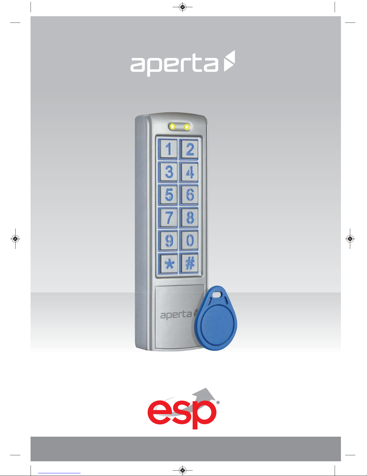
EZTAG3 | PROXIMITY AND KEYPAD DOOR ENTRY
EZTAG3 Manual.qxp_Layout 1 04/01/2016 11:47 Page 1
Page 2
2
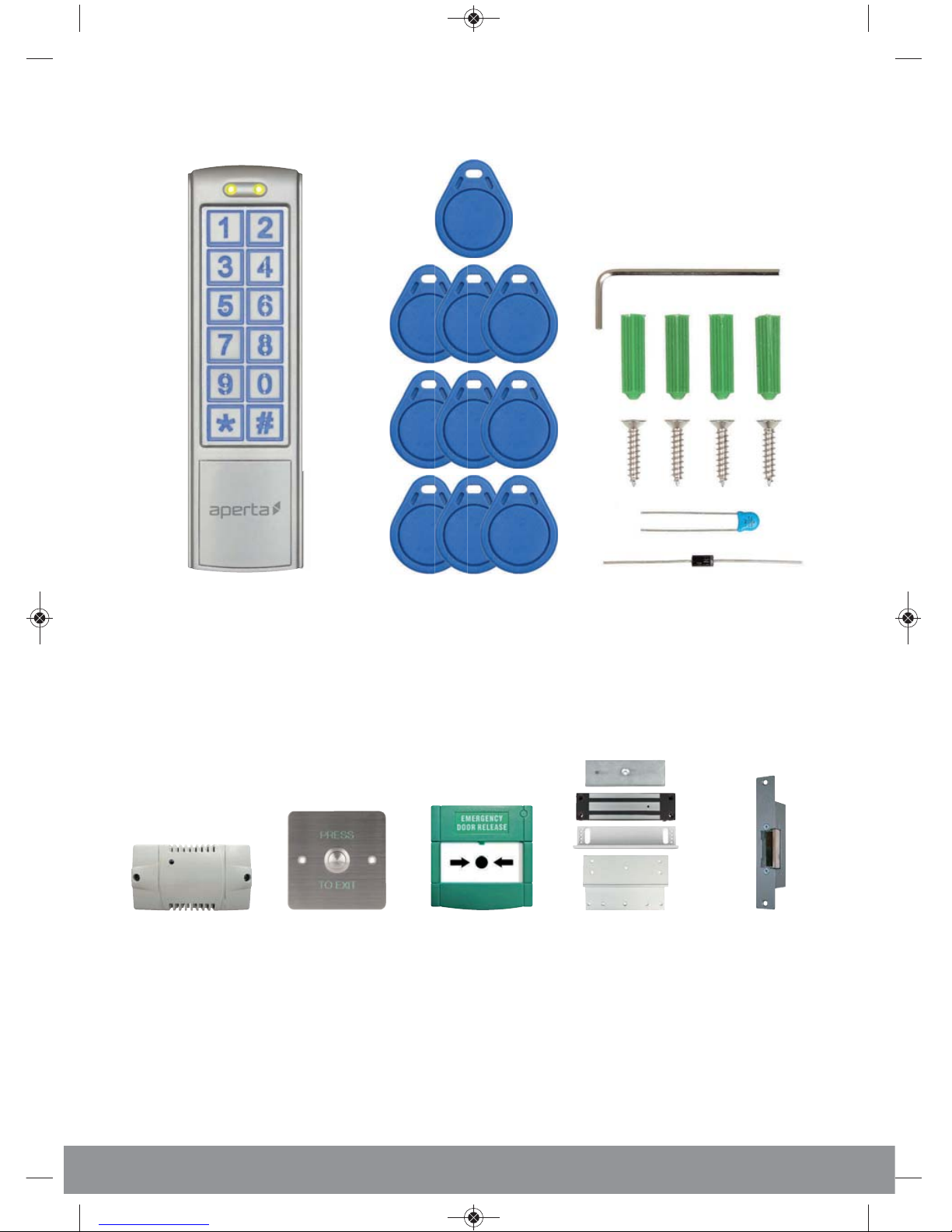
System Components
Proximity and Keypad Reader 10 x Proximity Tags 1 x Hex Key
4 x Plastic wall plug
4 x Countersunk screws
1 x Diode and 1 x Capacitor
Optional Accessories
EVBPSBB
Lock Power Supply
EV-EXIT
Push to Release
EV-EBG
Emergency Release
EV-ML-250/500XT
Electro-magnetic Lock
ENTERD
Electric Lock
EZTAG3 Manual.qxp_Layout 1 04/01/2016 11:47 Page 2
Page 3

3
Contents
Installation . . . . . . . . . . . . . . . . . . . . . . . . . . . . . . . . . . . . . . . . . . . . . . . . . . . . . . . . 4
EZTAG3 Wiring Example 1 . . . . . . . . . . . . . . . . . . . . . . . . . . . . . . . . . . . . . . . . . . 5
EZTAG3 Wiring Example 2 . . . . . . . . . . . . . . . . . . . . . . . . . . . . . . . . . . . . . . . . . . 5
Advanced Programming Guide
How to set-up Access Pin Number . . . . . . . . . . . . . . . . . . . . . . . . . . . . 6
How to set-up Access Tags . . . . . . . . . . . . . . . . . . . . . . . . . . . . . . . . . . . 6
Deleting Access Pin or Tag . . . . . . . . . . . . . . . . . . . . . . . . . . . . . . . . . . . . 7
Changing Programming Pin . . . . . . . . . . . . . . . . . . . . . . . . . . . . . . . . . . . 7
Clear all Pin and Tag Data . . . . . . . . . . . . . . . . . . . . . . . . . . . . . . . . . . . . . 8
Default to Factory Settings . . . . . . . . . . . . . . . . . . . . . . . . . . . . . . . . . . . . 8
Lock 1 Output Operating Time . . . . . . . . . . . . . . . . . . . . . . . . . . . . . . . . 9
Enable ‘Door Bell’ Facility . . . . . . . . . . . . . . . . . . . . . . . . . . . . . . . . . . . . . . 9
Enable ‘Tamper Alarm’ facility . . . . . . . . . . . . . . . . . . . . . . . . . . . . . . . . 10
Access Pin Number for Lock 2 Output . . . . . . . . . . . . . . . . . . . . . . . . 10
Deleting Access Pin for Lock 2 . . . . . . . . . . . . . . . . . . . . . . . . . . . . . . . . 11
Lock Output Operating Time for Lock 2 Output . . . . . . . . . . . . . . . . 11
System setup record . . . . . . . . . . . . . . . . . . . . . . . . . . . . . . . . . . . . . . . . . . . . . . 12
User Guide . . . . . . . . . . . . . . . . . . . . . . . . . . . . . . . . . . . . . . . . . . . . . . . . . . . . . . . 14
Technical Specification . . . . . . . . . . . . . . . . . . . . . . . . . . . . . . . . . . . . . . . . . . . . 14
EZTAG3 Manual.qxp_Layout 1 04/01/2016 11:47 Page 3
Page 4
4
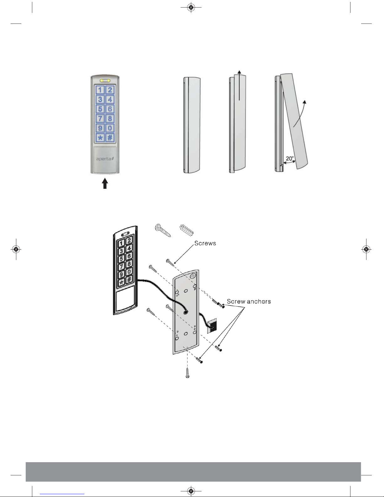
Installation
Note: if using more than one keypad, ensure that the keypads are mounted a minimum 185cm apart
(Side View)
Push the keypad up to release from mount plate
Release hex screw from
the bottom of the keypad
Thread system cable through the cable entry hole then make
the system connections (as per the wiring diagram), mount the
bracket to the surface and slide the keypad to the mountplate,
re-fit the hex screw to secure into position.
EZTAG3 Manual.qxp_Layout 1 04/01/2016 11:47 Page 4
Page 5
5
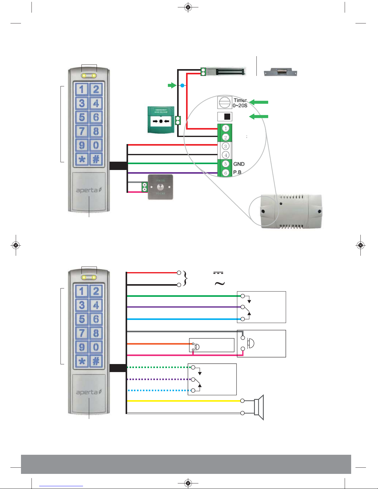
EZTAG3 Wiring Example 1
4
3
+
+
+
_
_
_
Red
NC
Black
Green
Purple
Grey
Pink
Electro-magnetic lock Electronic lock
Tag Reader
Indication LEDs
Keypad
Tag Reader
Indication LEDs
Keypad
EZTAG3 Wiring Example 2
Red
Black
Green/White
Purple/White
Yellow
White
Blue/White
Output for
Lock 2
(Volt-free)
N.O
COM
N.C
Speaker connection
for ‘door bell’ facility
(8 0.5w recommended)
Input DC:
+12V - +24V
Input AC:
12V - 24V
or
+
_
Grey
Orange
Pink
Push button
for Lock 1
(N.O)
P.b for Lock 2
(N.O)
Green
Purple
Blue
Output for
Lock 1
(Volt-free)
N.O
COM
N.C
Lock -release time
N.C for
Electro-magnetic lock
N.O for
Electronic lock
Capacitor for
Electro-magnetic lock
Diode for
Electronic Lock
EZTAG3 Manual.qxp_Layout 1 04/01/2016 11:47 Page 5
Page 6

6
ess Pin Number cc-up Aow to setH
ctionA
Number
tepS
9
02
????
##
6
5
4
3
2
1
ogrammingo end prT
t be used)(1234 no
ter a 4 digit pinEn
00
0
9
location number
ter a startingEn
ogrammingPr
ter En
(Default)
123412
Indication
ypad eK
ong L
34
T
ong L
T
ong L
Doubl
e
9
9
ccA-up ow to setH
ctionA
Number
tepS
9
05
1
5
4
3
2
???
00
0
9
location number*
ter a unusedEn
ed egistertags to be r
ter number ofEn
ogrammingPr
ter En
(Default)
12341
Indication
ypad eK
one T
ong L
234
one T
ong L
one T
ong L
9
9
##
6
7
ogrammingpr
*Each tag will use up a location number
egister will auto r
ther batch tagsAll o
est serial number wlo
t the tag with theesenPr
EZTAG3 Manual.qxp_Layout 1 04/01/2016 11:47 Page 6
Page 7

7
ccDeleting A
ctionA
Number
tepS
1
4
3
2
00
0
9
pinnumber of tag/
ter the location En
ogrammingPr
ter En
(Default)
12341
te
T
##
ogramming
T
Indication
ypad eK
one T
ong L
9
9
234
ogramming Pin Changing Pr
ctionA
Number
tepS
3
##
5
4
3
2
1
ogrammingPr
ter En
ogramming
????
ogramming pinpr
w 4 digitter neEn
????
ogramming pinpr
w 4 diter nee-enR
(Default)
12341
Indication
ypad eK
T
ong L
234
one T
ong L
git
eed in twicterode is enogramming cpr
ogramming mode, the 4 digit s prypad’eess kco acte; ToN
EZTAG3 Manual.qxp_Layout 1 04/01/2016 11:47 Page 7
Page 8

8
ctionA
Number
tepS
8
88
##
ogrammingPr
ter En
ogramming
4
3
2
1
(Default)
12341
2
Indication
ypad eK
ong L
34
T
ong L
actory SettingsDefault to F
ctionA
Number
tepS
8
99
##
ogrammingPr
ter En
ogramming
T
4
3
2
1
(Default)
12341
Indication
ypad eK
T
ong L
234
ong L
EZTAG3 Manual.qxp_Layout 1 04/01/2016 11:47 Page 8
Page 9

9
Lock 1 Output Operating Time
ctionA
Number
tepS
1
##
onds 00-99of sec
ter number En
ogrammingPr
ter En
ogramming
T
4
3
2
1
??
(Default)
12341
2
Indication
ypad eK
ong L
34
T
ong L
acilityEnable ‘Door Bell’ F
ctionA
Number
tepS
2
##
ogrammingPr
ter En
ogramming
4
3
2
1
02
T
door bell’ push in normal modeomes the ‘Bec
(Default)
12341
2
0 1
T
Indication
ypad eK
T
ong L
34
T
ong L
EZTAG3 Manual.qxp_Layout 1 04/01/2016 11:47 Page 9
Page 10

10
’ facilityamper AlarmEnable ‘T
ctionA
Number
tepS
6
##
ogrammingPr
ter En
ogramming
T
4
3
2
1
02
xposed t sensor is edoor bell’ output if the ligh‘
er and ternal buzzs inypad’eates the kamper alarm activT
T
(Default)
12341
2
0 1
Indication
ypad eK
ong L
34
T
ong L
disable
or Lock 2 Outpu
t
ess Pin Number fccA
ctionA
Number
tepS
9
03
????
5
4
3
2
1
t be used)(1234 should no
ter a 4 digit pinEn
00
location number
ter an unusedEn
ogrammingPr
ter En
(Default)
123412
0
9
Indication
ypad eK
T
ong L
34
ong L
ong L
T
Doubl
e
##
6
ogrammingo end prT
EZTAG3 Manual.qxp_Layout 1 04/01/2016 11:47 Page 10
Page 11

11
or Lock 2 ess Pin fccDeleting A
ctionA
Number
tepS
1
ogrammingPr
ter En
number of pin
ter the location En
4
3
2
(Default)
12341
te
T
##
ogramming
T
00
0
4
5
Indication
ypad eK
234
ong L
9
or Loc
k
Lock Output Operating Time f
ctionA
Number
tepS
5
##
onds 00-99of sec
ter number En
ogrammingPr
ter En
ogramming
T
4
3
2
1
??
(Default)
12341
2
2 Output
Indication
ypad eK
ong L
34
ong L
EZTAG3 Manual.qxp_Layout 1 04/01/2016 11:47 Page 11
Page 12

12
To assist in future programming, it is recommended that a
record is made of the system setup.
System Location Tag Serial
Tag Owner Notes
Number (000-999) Number
EZTAG3 Manual.qxp_Layout 1 04/01/2016 11:47 Page 12
Page 13

13
System Location Tag Serial
Tag Owner Notes
Number (000-999) Number
EZTAG3 Manual.qxp_Layout 1 04/01/2016 11:47 Page 13
Page 14

14
ed tagegisterr
t a esenPr
(B)
ess Pin numberccA
ogrammed ter a prEn
(A)
ock 1elease L
T
ogramming mode ess prc
(Default)
12341234
User Guide
Technical Specification
DC input 12 - 24volts
AC input 12 - 24volts
Standby current 80ma
Operating current (without lock) 110ma
Working temperature -20c to +50c
Reader frequency 125KHz
IP rating 65
Dimension 150 x 44 x 24mm
EZTAG3 Manual.qxp_Layout 1 04/01/2016 11:47 Page 14
Page 15

15
EZTAG3 Manual.qxp_Layout 1 04/01/2016 11:47 Page 15
Page 16

www.espuk.com
Elite Security Products
Unit 7, Target Park, Shawbank Rd
Lakeside, Redditch B98 8YN
Telephone: 01527 51 51 50
Fax: 01527 51 51 43
email: info@espuk.com
E&OE - Errors and omissions excepted. L15
EZTAG3 Manual.qxp_Layout 1 04/01/2016 11:47 Page 16
 Loading...