


SU7(Haswell) Series
SU7-2212G
Full-Featured Energy Efficient 2-Way Server
Technical Guide
Version: 2.0

COPYRIGHT
Copyright
Copyright © 2014 ESlim Computer Inc. This publication, including all photographs, illustrations and software, is protected under international copyright laws, with all rights
reserved. Neither this technical guide, nor any of the material contained herein, may be
reproduced without the express written consent of the manufacturer. All trademarks and
logos are copyrights of their respective owners.
Version 2.0 / November 25, 2014
Disclaimer
The information in this document is subject to change without notice. The manufacturer
makes no representations or warranties with respect to the contents hereof and specifically disclaims any implied warranties of merchantability or fitness for any particular purpose. Furthermore, the manufacturer reserves the right to revise this publication and to
make changes from time to time in the content hereof without obligation of the manufacturer to notify any person of such revision or changes.
For the latest information and updates please see www.eslim.co.kr
All the illustrations in this technical guide are for reference only and are subject to change
without prior notice.
I

T
ABLE
OF CONTENT
ABLE OF
T
ONTENT
C
About the System
Introduction . . . . . . . . . . . . . . . . . . . . . . . . . . . . . . . . . . . . . . . . . . . . . . . . . . . . . . . . . .
Package Contents . . . . . . . . . . . . . . . . . . . . . . . . . . . . . . . . . . . . . . . . . . . . . . . . . . . . .
A Tour of the System . . . . . . . . . . . . . . . . . . . . . . . . . . . . . . . . . . . . . . . . . . . . . . . . . .
System Overview . . . . . . . . . . . . . . . . . . . . . . . . . . . . . . . . . . . . . . . . . . . . . . . . .
System Front View . . . . . . . . . . . . . . . . . . . . . . . . . . . . . . . . . . . . . . . . . . . . .
System Rear View . . . . . . . . . . . . . . . . . . . . . . . . . . . . . . . . . . . . . . . . . . . . . .
LED Definitions. . . . . . . . . . . . . . . . . . . . . . . . . . . . . . . . . . . . . . . . . . . . . . . . . . 1-10
Front Control Panel LED . . . . . . . . . . . . . . . . . . . . . . . . . . . . . . . . . . . . . . . 1-10
LAN Port LEDs . . . . . . . . . . . . . . . . . . . . . . . . . . . . . . . . . . . . . . . . . . . . . . . . 1-11
1-1
1-4
1-5
1-5
1-7
1-9
HDD LED . . . . . . . . . . . . . . . . . . . . . . . . . . . . . . . . . . . . . . . . . . . . . . . . . . . . . 1-11
Installing Hardware
Safety Measures. . . . . . . . . . . . . . . . . . . . . . . . . . . . . . . . . . . . . . . . . . . . . . . . . . . . . . .
Hard Disk Drive Assembly . . . . . . . . . . . . . . . . . . . . . . . . . . . . . . . . . . . . . . . . . . . . .
Removing the HDD Assembly. . . . . . . . . . . . . . . . . . . . . . . . . . . . . . . . . . . . .
Installing the HDD Assembly. . . . . . . . . . . . . . . . . . . . . . . . . . . . . . . . . . . . . .
Solid-State Disk . . . . . . . . . . . . . . . . . . . . . . . . . . . . . . . . . . . . . . . . . . . . . . . . . . . . . . .
Removing the SSD Module . . . . . . . . . . . . . . . . . . . . . . . . . . . . . . . . . . . . . . .
Installing the SSD Module . . . . . . . . . . . . . . . . . . . . . . . . . . . . . . . . . . . . . . . .
Power Supply Unit . . . . . . . . . . . . . . . . . . . . . . . . . . . . . . . . . . . . . . . . . . . . . . . . . . . .
Removing a Power Supply Unit . . . . . . . . . . . . . . . . . . . . . . . . . . . . . . . . . . .
2-1
2-2
2-2
2-3
2-4
2-4
2-5
2-7
2-7
Installing a Power Supply Unit . . . . . . . . . . . . . . . . . . . . . . . . . . . . . . . . . . . .
2-8
II

T
ABLE
OF CONTENT
Top Cover. . . . . . . . . . . . . . . . . . . . . . . . . . . . . . . . . . . . . . . . . . . . . . . . . . . . . . . . . . . . .
Removing the Top Cover . . . . . . . . . . . . . . . . . . . . . . . . . . . . . . . . . . . . . . . . .
2-9
2-9
Installing the Top Cover . . . . . . . . . . . . . . . . . . . . . . . . . . . . . . . . . . . . . . . . . 2-10
Removing the Middle Top Cover . . . . . . . . . . . . . . . . . . . . . . . . . . . . . . . . . 2-11
Installing the Middle Top Cover . . . . . . . . . . . . . . . . . . . . . . . . . . . . . . . . . . 2-12
Fan Module . . . . . . . . . . . . . . . . . . . . . . . . . . . . . . . . . . . . . . . . . . . . . . . . . . . . . . . . . . 2-13
Removing the Fan Module. . . . . . . . . . . . . . . . . . . . . . . . . . . . . . . . . . . . . . . 2-13
Installing the Fan Module. . . . . . . . . . . . . . . . . . . . . . . . . . . . . . . . . . . . . . . . 2-14
SuperCap . . . . . . . . . . . . . . . . . . . . . . . . . . . . . . . . . . . . . . . . . . . . . . . . . . . . . . . . . . . . 2-16
Replacing the SuperCap Power Module (RAID Backup Unit) . . . . . . . 2-16
Installing a SuperCap . . . . . . . . . . . . . . . . . . . . . . . . . . . . . . . . . . . . . . . . . . . . 2-17
Expansion Cards . . . . . . . . . . . . . . . . . . . . . . . . . . . . . . . . . . . . . . . . . . . . . . . . . . . . . 2-18
Removing a PCIe Card . . . . . . . . . . . . . . . . . . . . . . . . . . . . . . . . . . . . . . . . . . . 2-18
Installing a PCIe Card . . . . . . . . . . . . . . . . . . . . . . . . . . . . . . . . . . . . . . . . . . . . 2-19
Expansion Assembly . . . . . . . . . . . . . . . . . . . . . . . . . . . . . . . . . . . . . . . . . . . . . . . . . 2-20
Removing the Expansion Assembly . . . . . . . . . . . . . . . . . . . . . . . . . . . . . . 2-20
Installing the Expansion Assembly . . . . . . . . . . . . . . . . . . . . . . . . . . . . . . . 2-21
PCIe Riser Board . . . . . . . . . . . . . . . . . . . . . . . . . . . . . . . . . . . . . . . . . . . . . . . . . . . . . . 2-23
Removing the PCIe Riser Board . . . . . . . . . . . . . . . . . . . . . . . . . . . . . . . . . . 2-23
Installing the PCIe Riser Board . . . . . . . . . . . . . . . . . . . . . . . . . . . . . . . . . . . 2-24
Mezzanine . . . . . . . . . . . . . . . . . . . . . . . . . . . . . . . . . . . . . . . . . . . . . . . . . . . . . . . . . . . 2-26
Removing a Mezzanine Assembly . . . . . . . . . . . . . . . . . . . . . . . . . . . . . . . . 2-26
Installing a Mezzanine Assembly . . . . . . . . . . . . . . . . . . . . . . . . . . . . . . . . . 2-27
OCP Mezzanine Board . . . . . . . . . . . . . . . . . . . . . . . . . . . . . . . . . . . . . . . . . . . . . . . . 2-29
Installing an OCP Mezzanine Board . . . . . . . . . . . . . . . . . . . . . . . . . . . . . . 2-29
Removing an OCP Mezzanine Board . . . . . . . . . . . . . . . . . . . . . . . . . . . . . 2-30
III

T
ABLE
OF CONTENT
Air Duct . . . . . . . . . . . . . . . . . . . . . . . . . . . . . . . . . . . . . . . . . . . . . . . . . . . . . . . . . . . . . . 2-32
Removing the Air Duct . . . . . . . . . . . . . . . . . . . . . . . . . . . . . . . . . . . . . . . . . . 2-32
Installing the Air Duct . . . . . . . . . . . . . . . . . . . . . . . . . . . . . . . . . . . . . . . . . . . 2-33
Processor Heat Sink . . . . . . . . . . . . . . . . . . . . . . . . . . . . . . . . . . . . . . . . . . . . . . . . . . 2-34
Removing the Processor Heat Sink . . . . . . . . . . . . . . . . . . . . . . . . . . . . . . . 2-34
Installing the Processor Heat Sink . . . . . . . . . . . . . . . . . . . . . . . . . . . . . . . . 2-35
Processor . . . . . . . . . . . . . . . . . . . . . . . . . . . . . . . . . . . . . . . . . . . . . . . . . . . . . . . . . . . . 2-36
Removing the Processor . . . . . . . . . . . . . . . . . . . . . . . . . . . . . . . . . . . . . . . . . 2-36
Installing the Processor . . . . . . . . . . . . . . . . . . . . . . . . . . . . . . . . . . . . . . . . . . 2-37
Memory Modules . . . . . . . . . . . . . . . . . . . . . . . . . . . . . . . . . . . . . . . . . . . . . . . . . . . . 2-39
General Guidelines . . . . . . . . . . . . . . . . . . . . . . . . . . . . . . . . . . . . . . . . . . . . . . 2-39
Memory Population Support. . . . . . . . . . . . . . . . . . . . . . . . . . . . . . . . . . . . . 2-39
Removing a Memory Module . . . . . . . . . . . . . . . . . . . . . . . . . . . . . . . . . . . . 2-40
Installing a Memory Module . . . . . . . . . . . . . . . . . . . . . . . . . . . . . . . . . . . . . 2-41
Mainboard . . . . . . . . . . . . . . . . . . . . . . . . . . . . . . . . . . . . . . . . . . . . . . . . . . . . . . . . . . . 2-42
Removing the Mainboard. . . . . . . . . . . . . . . . . . . . . . . . . . . . . . . . . . . . . . . . 2-42
Installing the Mainboard. . . . . . . . . . . . . . . . . . . . . . . . . . . . . . . . . . . . . . . . . 2-43
Hard Disk Drive Backplane . . . . . . . . . . . . . . . . . . . . . . . . . . . . . . . . . . . . . . . . . . . . 2-44
Locating the HDD Backplane. . . . . . . . . . . . . . . . . . . . . . . . . . . . . . . . . . . . . 2-44
Removing the Backplane (2.5”). . . . . . . . . . . . . . . . . . . . . . . . . . . . . . . . . . . 2-45
Installing the Backplane (2.5”). . . . . . . . . . . . . . . . . . . . . . . . . . . . . . . . . . . . 2-46
Removing the HDD Backplane (3.5”) . . . . . . . . . . . . . . . . . . . . . . . . . . . . . 2-47
Installing the HDD Backplane (3.5”) . . . . . . . . . . . . . . . . . . . . . . . . . . . . . . 2-48
SSD Air Duct . . . . . . . . . . . . . . . . . . . . . . . . . . . . . . . . . . . . . . . . . . . . . . . . . . . . . . . . . 2-49
Removing the SSD Air Duct . . . . . . . . . . . . . . . . . . . . . . . . . . . . . . . . . . . . . . 2-49
Installing the SSD Air Duct . . . . . . . . . . . . . . . . . . . . . . . . . . . . . . . . . . . . . . . 2-50
IV

T
ABLE
OF CONTENT
SSD Fan Module. . . . . . . . . . . . . . . . . . . . . . . . . . . . . . . . . . . . . . . . . . . . . . . . . . . . . . 2-51
Removing a SSD Fan Module . . . . . . . . . . . . . . . . . . . . . . . . . . . . . . . . . . . . 2-51
Installing a SSD Fan Module . . . . . . . . . . . . . . . . . . . . . . . . . . . . . . . . . . . . . 2-52
SSD Backplane . . . . . . . . . . . . . . . . . . . . . . . . . . . . . . . . . . . . . . . . . . . . . . . . . . . . . . . 2-53
Removing a SSD Backplane . . . . . . . . . . . . . . . . . . . . . . . . . . . . . . . . . . . . . . 2-53
Installing a SSD Backplane . . . . . . . . . . . . . . . . . . . . . . . . . . . . . . . . . . . . . . . 2-55
Expander Board . . . . . . . . . . . . . . . . . . . . . . . . . . . . . . . . . . . . . . . . . . . . . . . . . . . . . . 2-58
Removing an Expander Board. . . . . . . . . . . . . . . . . . . . . . . . . . . . . . . . . . . . 2-58
Installing an Expander Board. . . . . . . . . . . . . . . . . . . . . . . . . . . . . . . . . . . . . 2-59
Front Panel Board . . . . . . . . . . . . . . . . . . . . . . . . . . . . . . . . . . . . . . . . . . . . . . . . . . . . 2-60
Removing the Front Panel Board . . . . . . . . . . . . . . . . . . . . . . . . . . . . . . . . . 2-60
Installing the Front Panel Board . . . . . . . . . . . . . . . . . . . . . . . . . . . . . . . . . . 2-61
USB Board . . . . . . . . . . . . . . . . . . . . . . . . . . . . . . . . . . . . . . . . . . . . . . . . . . . . . . . . . . . 2-63
Removing the USB Board . . . . . . . . . . . . . . . . . . . . . . . . . . . . . . . . . . . . . . . . 2-63
Installing the USB Board . . . . . . . . . . . . . . . . . . . . . . . . . . . . . . . . . . . . . . . . . 2-65
BIOS
BIOS Setup Utility . . . . . . . . . . . . . . . . . . . . . . . . . . . . . . . . . . . . . . . . . . . . . . . . . . . . .
Operation . . . . . . . . . . . . . . . . . . . . . . . . . . . . . . . . . . . . . . . . . . . . . . . . . . . . . . . .
Setup Page Layout . . . . . . . . . . . . . . . . . . . . . . . . . . . . . . . . . . . . . . . . . . . . . . .
Entering BIOS Setup . . . . . . . . . . . . . . . . . . . . . . . . . . . . . . . . . . . . . . . . . . . . . .
Keyboard Commands . . . . . . . . . . . . . . . . . . . . . . . . . . . . . . . . . . . . . . . . . . . .
Menu Selection Bar . . . . . . . . . . . . . . . . . . . . . . . . . . . . . . . . . . . . . . . . . . . . . . .
Server Platform Setup Utility Screens. . . . . . . . . . . . . . . . . . . . . . . . . . . . . .
3-1
3-1
3-1
3-1
3-2
3-3
3-4
Main Screen . . . . . . . . . . . . . . . . . . . . . . . . . . . . . . . . . . . . . . . . . . . . . . . . . . . . . .
Advanced Screen. . . . . . . . . . . . . . . . . . . . . . . . . . . . . . . . . . . . . . . . . . . . . . . . .
Super IO Configuration. . . . . . . . . . . . . . . . . . . . . . . . . . . . . . . . . . . . . . . . .
SATA Configuration . . . . . . . . . . . . . . . . . . . . . . . . . . . . . . . . . . . . . . . . . . . .
Serial Port Console Redirection . . . . . . . . . . . . . . . . . . . . . . . . . . . . . . . . 3-10
V
3-4
3-5
3-7
3-9

T
ABLE
OF CONTENT
Onboard Device Configuration . . . . . . . . . . . . . . . . . . . . . . . . . . . . . . . . 3-14
PCI Subsystem Settings . . . . . . . . . . . . . . . . . . . . . . . . . . . . . . . . . . . . . . . 3-15
CSM Configuration. . . . . . . . . . . . . . . . . . . . . . . . . . . . . . . . . . . . . . . . . . . . 3-17
Trusted Computing . . . . . . . . . . . . . . . . . . . . . . . . . . . . . . . . . . . . . . . . . . . 3-18
USB Configuration . . . . . . . . . . . . . . . . . . . . . . . . . . . . . . . . . . . . . . . . . . . . 3-19
IntelRCSetup Screen . . . . . . . . . . . . . . . . . . . . . . . . . . . . . . . . . . . . . . . . . . . . . 3-19
Processor Configuration. . . . . . . . . . . . . . . . . . . . . . . . . . . . . . . . . . . . . . . 3-21
Advanced Power Management Configuration . . . . . . . . . . . . . . . . . 3-24
Common RefCode Configuration . . . . . . . . . . . . . . . . . . . . . . . . . . . . . . 3-29
QPI Configuration. . . . . . . . . . . . . . . . . . . . . . . . . . . . . . . . . . . . . . . . . . . . . 3-30
Memory Configuration . . . . . . . . . . . . . . . . . . . . . . . . . . . . . . . . . . . . . . . . 3-32
IIO Configuration . . . . . . . . . . . . . . . . . . . . . . . . . . . . . . . . . . . . . . . . . . . . . 3-35
PCH Configuration . . . . . . . . . . . . . . . . . . . . . . . . . . . . . . . . . . . . . . . . . . . . 3-40
Server ME Configuration . . . . . . . . . . . . . . . . . . . . . . . . . . . . . . . . . . . . . . 3-47
Runtime Error Logging . . . . . . . . . . . . . . . . . . . . . . . . . . . . . . . . . . . . . . . . 3-48
Server Management Screen. . . . . . . . . . . . . . . . . . . . . . . . . . . . . . . . . . . . . . 3-49
System Event Log . . . . . . . . . . . . . . . . . . . . . . . . . . . . . . . . . . . . . . . . . . . . . 3-51
View FRU information . . . . . . . . . . . . . . . . . . . . . . . . . . . . . . . . . . . . . . . . . . . 3-52
BMC network configuration . . . . . . . . . . . . . . . . . . . . . . . . . . . . . . . . . . . 3-53
Boot Options Screen. . . . . . . . . . . . . . . . . . . . . . . . . . . . . . . . . . . . . . . . . . . . . 3-54
UEFI Network Drive BBS Priorities . . . . . . . . . . . . . . . . . . . . . . . . . . . . . . 3-57
Security Screen. . . . . . . . . . . . . . . . . . . . . . . . . . . . . . . . . . . . . . . . . . . . . . . . . . 3-58
Secure Boot menu . . . . . . . . . . . . . . . . . . . . . . . . . . . . . . . . . . . . . . . . . . . . 3-59
Exit Screen . . . . . . . . . . . . . . . . . . . . . . . . . . . . . . . . . . . . . . . . . . . . . . . . . . . . . . 3-62
Loading BIOS Defaults . . . . . . . . . . . . . . . . . . . . . . . . . . . . . . . . . . . . . . . . . . . 3-64
BIOS Update Utility . . . . . . . . . . . . . . . . . . . . . . . . . . . . . . . . . . . . . . . . . . . . . . . . . . . 3-65
BIOS Update Utility . . . . . . . . . . . . . . . . . . . . . . . . . . . . . . . . . . . . . . . . . . . . . . 3-65
AFULNX: v2.39 . . . . . . . . . . . . . . . . . . . . . . . . . . . . . . . . . . . . . . . . . . . . . . . . 3-65
ME Region Update . . . . . . . . . . . . . . . . . . . . . . . . . . . . . . . . . . . . . . . . . . . . 3-65
BIOS Setting Utility . . . . . . . . . . . . . . . . . . . . . . . . . . . . . . . . . . . . . . . . . . . . 3-66
BIOS Revision . . . . . . . . . . . . . . . . . . . . . . . . . . . . . . . . . . . . . . . . . . . . . . . . . 3-66
Clear CMOS . . . . . . . . . . . . . . . . . . . . . . . . . . . . . . . . . . . . . . . . . . . . . . . . . . . . . 3-69
Clear Password . . . . . . . . . . . . . . . . . . . . . . . . . . . . . . . . . . . . . . . . . . . . . . . . . . 3-69
VI

T
ABLE
OF CONTENT
Server Management. . . . . . . . . . . . . . . . . . . . . . . . . . . . . . . . . . . . . . . . . . . . . . . . . . 3-70
Console Redirection . . . . . . . . . . . . . . . . . . . . . . . . . . . . . . . . . . . . . . . . . . . . . 3-70
Serial Configuration Settings . . . . . . . . . . . . . . . . . . . . . . . . . . . . . . . . . . 3-70
Keystroke Mapping . . . . . . . . . . . . . . . . . . . . . . . . . . . . . . . . . . . . . . . . . . . 3-70
Reset . . . . . . . . . . . . . . . . . . . . . . . . . . . . . . . . . . . . . . . . . . . . . . . . . . . . . . . . . 3-71
Limitations . . . . . . . . . . . . . . . . . . . . . . . . . . . . . . . . . . . . . . . . . . . . . . . . . . . 3-71
Interface to Server Management (Optional) . . . . . . . . . . . . . . . . . . . . 3-72
Network BIOS Support. . . . . . . . . . . . . . . . . . . . . . . . . . . . . . . . . . . . . . . . . . . 3-72
PXE Boot. . . . . . . . . . . . . . . . . . . . . . . . . . . . . . . . . . . . . . . . . . . . . . . . . . . . . . 3-72
Checkpoints. . . . . . . . . . . . . . . . . . . . . . . . . . . . . . . . . . . . . . . . . . . . . . . . . . . . . 3-72
Debug Header . . . . . . . . . . . . . . . . . . . . . . . . . . . . . . . . . . . . . . . . . . . . . . . . 3-72
Standard Checkpoint. . . . . . . . . . . . . . . . . . . . . . . . . . . . . . . . . . . . . . . . . . 3-73
ACPI/ASL Checkpoints . . . . . . . . . . . . . . . . . . . . . . . . . . . . . . . . . . . . . . . . 3-78
OEM-Reserved Checkpoint Ranges . . . . . . . . . . . . . . . . . . . . . . . . . . . . 3-79
BMC
Server Management Software . . . . . . . . . . . . . . . . . . . . . . . . . . . . . . . . . . . . . . . . .
Server System Overview . . . . . . . . . . . . . . . . . . . . . . . . . . . . . . . . . . . . . . . . . .
BMC Key Features and Functions. . . . . . . . . . . . . . . . . . . . . . . . . . . . . . . . . .
Power System . . . . . . . . . . . . . . . . . . . . . . . . . . . . . . . . . . . . . . . . . . . . . . . . . . . .
Front Panel User Interface . . . . . . . . . . . . . . . . . . . . . . . . . . . . . . . . . . . . . . . .
Power Button . . . . . . . . . . . . . . . . . . . . . . . . . . . . . . . . . . . . . . . . . . . . . . . . . .
ID Button . . . . . . . . . . . . . . . . . . . . . . . . . . . . . . . . . . . . . . . . . . . . . . . . . . . . . .
LEDs. . . . . . . . . . . . . . . . . . . . . . . . . . . . . . . . . . . . . . . . . . . . . . . . . . . . . . . . . . .
LAN Interface. . . . . . . . . . . . . . . . . . . . . . . . . . . . . . . . . . . . . . . . . . . . . . . . . . . . .
4-1
4-1
4-1
4-1
4-2
4-2
4-2
4-2
4-5
Session and User . . . . . . . . . . . . . . . . . . . . . . . . . . . . . . . . . . . . . . . . . . . . . . .
Serial Over LAN. . . . . . . . . . . . . . . . . . . . . . . . . . . . . . . . . . . . . . . . . . . . . . . . . . .
Time Sync . . . . . . . . . . . . . . . . . . . . . . . . . . . . . . . . . . . . . . . . . . . . . . . . . . . . . . . .
SEL . . . . . . . . . . . . . . . . . . . . . . . . . . . . . . . . . . . . . . . . . . . . . . . . . . . . . . . . . . . . . .
Platform Event . . . . . . . . . . . . . . . . . . . . . . . . . . . . . . . . . . . . . . . . . . . . . . . . . . .
Platform Event Filter . . . . . . . . . . . . . . . . . . . . . . . . . . . . . . . . . . . . . . . . . . .
BMC Firmware Update. . . . . . . . . . . . . . . . . . . . . . . . . . . . . . . . . . . . . . . . . . . .
VII
4-5
4-5
4-6
4-6
4-6
4-6
4-6

T
ABLE
OF CONTENT
DOS Recovery Utility . . . . . . . . . . . . . . . . . . . . . . . . . . . . . . . . . . . . . . . . . . .
4-6
WebUI Update . . . . . . . . . . . . . . . . . . . . . . . . . . . . . . . . . . . . . . . . . . . . . . . . .
BMC Recovery. . . . . . . . . . . . . . . . . . . . . . . . . . . . . . . . . . . . . . . . . . . . . . . . . . . . . . . . .
Recovery Process in DOS System . . . . . . . . . . . . . . . . . . . . . . . . . . . . . . . . . .
Recovery Process in Linux System . . . . . . . . . . . . . . . . . . . . . . . . . . . . . . . . .
Recovery Process in Windows System . . . . . . . . . . . . . . . . . . . . . . . . . . . . .
SMASH. . . . . . . . . . . . . . . . . . . . . . . . . . . . . . . . . . . . . . . . . . . . . . . . . . . . . . . . . . . . . . . .
4-7
4-8
4-8
4-8
4-8
4-9
System Level Commands. . . . . . . . . . . . . . . . . . . . . . . . . . . . . . . . . . . . . . 4-10
BMC Information. . . . . . . . . . . . . . . . . . . . . . . . . . . . . . . . . . . . . . . . . . . . . . 4-14
Web Graphical User Interface (GUI) for ESMS . . . . . . . . . . . . . . . . . . . . . . . . . . 4-16
Using the Web GUI . . . . . . . . . . . . . . . . . . . . . . . . . . . . . . . . . . . . . . . . . . . . . . 4-16
Login . . . . . . . . . . . . . . . . . . . . . . . . . . . . . . . . . . . . . . . . . . . . . . . . . . . . . . . . . . . 4-16
Dashboard . . . . . . . . . . . . . . . . . . . . . . . . . . . . . . . . . . . . . . . . . . . . . . . . . . . . . . 4-17
Device Information . . . . . . . . . . . . . . . . . . . . . . . . . . . . . . . . . . . . . . . . . . . 4-18
Network Information. . . . . . . . . . . . . . . . . . . . . . . . . . . . . . . . . . . . . . . . . . 4-19
Sensor Monitoring . . . . . . . . . . . . . . . . . . . . . . . . . . . . . . . . . . . . . . . . . . . . 4-19
Event Logs. . . . . . . . . . . . . . . . . . . . . . . . . . . . . . . . . . . . . . . . . . . . . . . . . . . . 4-19
Server Information . . . . . . . . . . . . . . . . . . . . . . . . . . . . . . . . . . . . . . . . . . . . . . 4-19
FRU Information. . . . . . . . . . . . . . . . . . . . . . . . . . . . . . . . . . . . . . . . . . . . . . . . . 4-20
Server Component . . . . . . . . . . . . . . . . . . . . . . . . . . . . . . . . . . . . . . . . . . . . 4-22
Server identify . . . . . . . . . . . . . . . . . . . . . . . . . . . . . . . . . . . . . . . . . . . . . . . . 4-23
BIOS POST Code . . . . . . . . . . . . . . . . . . . . . . . . . . . . . . . . . . . . . . . . . . . . . . 4-24
Server Health Group . . . . . . . . . . . . . . . . . . . . . . . . . . . . . . . . . . . . . . . . . . 4-24
Sensor Readings . . . . . . . . . . . . . . . . . . . . . . . . . . . . . . . . . . . . . . . . . . . . . . 4-25
Event Log. . . . . . . . . . . . . . . . . . . . . . . . . . . . . . . . . . . . . . . . . . . . . . . . . . . . . 4-27
Configuration Group . . . . . . . . . . . . . . . . . . . . . . . . . . . . . . . . . . . . . . . . . . . . 4-29
Active Directory. . . . . . . . . . . . . . . . . . . . . . . . . . . . . . . . . . . . . . . . . . . . . . . 4-29
DNS . . . . . . . . . . . . . . . . . . . . . . . . . . . . . . . . . . . . . . . . . . . . . . . . . . . . . . . . . . 4-32
LDAP/E-Directory . . . . . . . . . . . . . . . . . . . . . . . . . . . . . . . . . . . . . . . . . . . . . 4-34
Mouse Mode. . . . . . . . . . . . . . . . . . . . . . . . . . . . . . . . . . . . . . . . . . . . . . . . . . 4-37
Network . . . . . . . . . . . . . . . . . . . . . . . . . . . . . . . . . . . . . . . . . . . . . . . . . . . . . . 4-38
VIII

T
ABLE
OF CONTENT
PEF . . . . . . . . . . . . . . . . . . . . . . . . . . . . . . . . . . . . . . . . . . . . . . . . . . . . . . . . . . . 4-41
RADIUS . . . . . . . . . . . . . . . . . . . . . . . . . . . . . . . . . . . . . . . . . . . . . . . . . . . . . . . 4-49
Remote Session . . . . . . . . . . . . . . . . . . . . . . . . . . . . . . . . . . . . . . . . . . . . . . . 4-50
SMTP . . . . . . . . . . . . . . . . . . . . . . . . . . . . . . . . . . . . . . . . . . . . . . . . . . . . . . . . . 4-51
SOL. . . . . . . . . . . . . . . . . . . . . . . . . . . . . . . . . . . . . . . . . . . . . . . . . . . . . . . . . . . 4-54
SSL . . . . . . . . . . . . . . . . . . . . . . . . . . . . . . . . . . . . . . . . . . . . . . . . . . . . . . . . . . . 4-54
User Management . . . . . . . . . . . . . . . . . . . . . . . . . . . . . . . . . . . . . . . . . . . . 4-58
Virtual Media . . . . . . . . . . . . . . . . . . . . . . . . . . . . . . . . . . . . . . . . . . . . . . . . . 4-62
SNMP . . . . . . . . . . . . . . . . . . . . . . . . . . . . . . . . . . . . . . . . . . . . . . . . . . . . . . . . . . . 4-63
UTC Timezone. . . . . . . . . . . . . . . . . . . . . . . . . . . . . . . . . . . . . . . . . . . . . . . . . . . 4-63
LAN Port Settings. . . . . . . . . . . . . . . . . . . . . . . . . . . . . . . . . . . . . . . . . . . . . . . . 4-64
Remote Control . . . . . . . . . . . . . . . . . . . . . . . . . . . . . . . . . . . . . . . . . . . . . . . . . 4-65
Console Redirection. . . . . . . . . . . . . . . . . . . . . . . . . . . . . . . . . . . . . . . . . . . 4-65
Server Power Control . . . . . . . . . . . . . . . . . . . . . . . . . . . . . . . . . . . . . . . . . 4-73
Maintenance Group . . . . . . . . . . . . . . . . . . . . . . . . . . . . . . . . . . . . . . . . . . . . . 4-73
BMC Firmware Update . . . . . . . . . . . . . . . . . . . . . . . . . . . . . . . . . . . . . . . . 4-74
BIOS Update . . . . . . . . . . . . . . . . . . . . . . . . . . . . . . . . . . . . . . . . . . . . . . . . . . 4-75
Preserve Configuration. . . . . . . . . . . . . . . . . . . . . . . . . . . . . . . . . . . . . . . . 4-75
Restore Factory Defaults . . . . . . . . . . . . . . . . . . . . . . . . . . . . . . . . . . . . . . 4-77
Log Out . . . . . . . . . . . . . . . . . . . . . . . . . . . . . . . . . . . . . . . . . . . . . . . . . . . . . . . . . 4-78
User Privilege . . . . . . . . . . . . . . . . . . . . . . . . . . . . . . . . . . . . . . . . . . . . . . . . . . . 4-78
Connectors and Jumpers
Connectors and Jumpers . . . . . . . . . . . . . . . . . . . . . . . . . . . . . . . . . . . . . . . . . . . . . .
Mainboard . . . . . . . . . . . . . . . . . . . . . . . . . . . . . . . . . . . . . . . . . . . . . . . . . . . . . . .
5-1
5-1
Connectors . . . . . . . . . . . . . . . . . . . . . . . . . . . . . . . . . . . . . . . . . . . . . . . . . . . .
Jumpers . . . . . . . . . . . . . . . . . . . . . . . . . . . . . . . . . . . . . . . . . . . . . . . . . . . . . . .
HDD Backplane. . . . . . . . . . . . . . . . . . . . . . . . . . . . . . . . . . . . . . . . . . . . . . . . . . .
USB Board. . . . . . . . . . . . . . . . . . . . . . . . . . . . . . . . . . . . . . . . . . . . . . . . . . . . . . . .
PCIe SSD Backplane . . . . . . . . . . . . . . . . . . . . . . . . . . . . . . . . . . . . . . . . . . . . . .
SAS/SATA SSD Backplane . . . . . . . . . . . . . . . . . . . . . . . . . . . . . . . . . . . . . . . . .
IX
5-1
5-3
5-3
5-5
5-6
5-6

Troubleshooting
T
ABLE
OF CONTENT
Troubleshooting . . . . . . . . . . . . . . . . . . . . . . . . . . . . . . . . . . . . . . . . . . . . . . . . . . . . . .
BIOS checkpoints. . . . . . . . . . . . . . . . . . . . . . . . . . . . . . . . . . . . . . . . . . . . . . . . .
Intel Memory Reference Code Checkpoints . . . . . . . . . . . . . . . . . . . . .
Hardware Failure . . . . . . . . . . . . . . . . . . . . . . . . . . . . . . . . . . . . . . . . . . . . . . . . .
HDD SMART failure. . . . . . . . . . . . . . . . . . . . . . . . . . . . . . . . . . . . . . . . . . . . .
HDD not ready, or server does not see hard disk drive . . . . . . . . . . .
HDD SATA failure . . . . . . . . . . . . . . . . . . . . . . . . . . . . . . . . . . . . . . . . . . . . . .
Motherboard No Boot. . . . . . . . . . . . . . . . . . . . . . . . . . . . . . . . . . . . . . . . . .
Motherboard fails single bit ECC Errors. . . . . . . . . . . . . . . . . . . . . . . . . .
Motherboard fails multiple bit error or rebooting . . . . . . . . . . . . . . .
Motherboard fails 1G Ethernet port . . . . . . . . . . . . . . . . . . . . . . . . . . . . .
Motherboard fails for PXE, 10G Mellanox. . . . . . . . . . . . . . . . . . . . . . . .
Motherboard rebooting . . . . . . . . . . . . . . . . . . . . . . . . . . . . . . . . . . . . . . . .
Fan failure . . . . . . . . . . . . . . . . . . . . . . . . . . . . . . . . . . . . . . . . . . . . . . . . . . . . .
6-1
6-1
6-1
6-2
6-2
6-2
6-2
6-2
6-2
6-3
6-3
6-3
6-4
6-4
Hardware Failure Troubleshooting Matrix . . . . . . . . . . . . . . . . . . . . . . . . .
SOL . . . . . . . . . . . . . . . . . . . . . . . . . . . . . . . . . . . . . . . . . . . . . . . . . . . . . . . . . . . . . .
Regulatory and Compliance Information
6-5
6-7
X

CONVENTIONS
Conventions
Several different typographic conventions are used throughout this manual. Refer to the
following examples for common usage.
Bold
type face denotes menu items, buttons and application names.
Italic type face denotes references to other sections, and the names of the folders, menus,
programs, and files.
<Enter> type face denotes keyboard keys.
.Warning information appears before the text it references and should not be ignored as
the content may prevent damage to the device.
!
!
WARNING!
Warning information appears before the text it references and should not be ignored as the
content may prevent damage to the device.
CAUTION!
CAUTIONS APPEAR BEFORE THE
APPEAR IN CAPITAL LETTERS AND CONTAIN
TEXT
IT REFERENCES, SIMILAR TO NOTES AND WARNINGS. CAUTIONS, HOWEVER,
VITAL
HEALTH AND SAFETY INFORMATION.
Note:
Highlights general or useful information and tips.
XI

Table 1: Warning and Cautions
CAUTION
Indicates the presence of a hazard that may cause minor personal injury or property damage if the CAUTION is ignored.
WARNING
Indicates the presence of a hazard that may result in serious personal injury if the
WARNING is ignored.
Indicates potential hazard if indicated information is ignored.
Indicates shock hazards that result in serious injury or death if safety instructions
are not followed.
Indicates hot components or surfaces.
Indicates do not touch fan blades, may result in injury.
Remove the system from the rack to disconnect power system.
PRECAUTIONARY MEASURES
Precautionary Measures
Read all caution and safety statements in this document before performing any of the
instructions. To reduce the risk of bodily injury, electrical shock, fire, and equipment damage, read and observe all warnings and precautions in this chapter before installing or
maintaining your system. To avoid personal injury or property damage, before you begin
installing the product, read, observe, and adhere to all of the following instructions and
information. The following symbols may be used throughout this guide and may be
marked on the product and / or the product packaging.
Safety Instructions about your system
In the event of a conflict between the information in this guide and information provided
with the product or on the website for a particular product, the product documentation
takes precedence.
Your system should be integrated and serviced only by technically qualified persons.
You must adhere to the guidelines in this guide and the assembly instructions in related
chapters to ensure and maintain compliance with existing product certifications and
approvals. Use only the described, regulated components specified in this guide. Use of
other products / components will void the UL Listing and other regulatory approvals of
the product, and may result in noncompliance with product regulations in the region(s) in
which the product is sold.
XII

Table 1: Warning and Cautions (Continued)
The enclosure is designed to carry only the weight of the system sled. Do not use
this equipment as a workspace. Do not place additional load onto any equipment
in this system.
Indicates two people are required to safely handle the system.
Restricted Access Location:
The system is intended for installation only in a
Server Room or Computer Room where both these conditions apply:
access can only be gained by SERVICE PERSONS or by USERS who have been
instructed about the reasons for the restrictions applied to the location and
about any precautions that shall be taken; and
access is through the use of a TOOL or lock and key, or other means of security,
and is controlled by the authority responsible for the location.
PRECAUTIONARY MEASURES
Intended Application Uses
This product was evaluated as Information Technology Equipment (ITE), which may be
installed in offices, schools, computer rooms, and similar commercial type locations. The
suitability of this product for other product categories and environments (such as medical,
industrial, residential, alarm systems, and test equipment), other than an ITE application,
may require further evaluation.
Site Selection
The system is designed to operate in a typical office environment. Choose a site that is:
Clean, dry, and free of airborne particles (other than normal room dust).
Well-ventilated and away from sources of heat including direct sunlight and radiators.
Away from sources of vibration or physical shock.
Isolated from strong electromagnetic fields produced by electrical devices.
In regions that are susceptible to electrical storms, we recommend you plug your
system into a surge suppressor and disconnect telecommunication lines to your
modem during an electrical storm.
Provided with a properly grounded wall outlet.
Provided with sufficient space to access the power system, because they serve as the
product's main power disconnect.
Provided with either two independent DC power system or two independent phases
from a single power system.
XIII

Equipment Handling Practices
Reduce the risk of personal injury or equipment damage:
Conform to local occupational health and safety requirements when moving and
lifting equipment.
Use mechanical assistance or other suitable assistance when moving and lifting
equipment.
To reduce the weight for easier handling, remove any easily detachable compo-
nents.
Never lift or move your system soley by the handle on the component.
Power and Electrical Warnings
CAUTION!
M
AKE
!
!
SURE THE SYSTEM IS REMOVED FROM THE
THE BUS
TEM FROM THE POWER SOURCE.
BAR
CAUTION!
TO AVOID RISK OF ELECTRIC SHOCK, DISCONNECT
FROM THE
RACK
BEFORE SERVICING
CLIPS MUST BE DISCONNECTED FROM THE POWER SYSTEM INORDER TO
ALL
CABLING FROM THE SYSTEM AND REMOVE THE SYSTEM
RACK
.
System Access Warnings
PRECAUTIONARY MEASURES
ANY
NON-HOT PLUG COMPONENTS.
FULLY
SEPARATE THE SYS-
CAUTION!
!
TO AVOID PERSONAL INJURY OR PROPERTY DAMAGE, THE FOLLOWING SAFETY INSTRUCTIONS APPLY WHENEVER
ACCESSING THE INSIDE OF THE PRODUCT:
Disconnect from the power source by removing the system from the rack.
Disconnect all cabling running into the system.
Retain all screws or other fasteners when servicing. Upon completion servicing, sercure
with original screws or fasteners.
CAUTION!
!
IF THE SERVER HAS BEEN RUNNING,
CAUTION!
!
UNLESS YOU
VICING.
CAUTION!
!
TO AVOID INJURY DO NOT CONTACT MOVING FAN BLADES. IF YOUR SYSTEM IS SUPPLIED WITH A GUARD OVER THE
FAN, DO NOT OPERATE THE SYSTEM WITHOUT THE FAN GUARD IN PLACE.
ANY
INSTALLED HDD MODULES
ARE
ADDING OR REMOVING A HOT-PLUG COMPONENT, ALLOW THE SYSTEM TO COOL BEFORE SER-
MAY BE
HOT.
XIV

PRECAUTIONARY MEASURES
Rack Mount Warnings
The following installation guidelines are required by UL for maintaining safety compliance
when installing your system into a rack.
The equipment rack must be anchored to an unmovable support to prevent it from tipping when your system or piece of equipment is extended from it. The equipment rack
must be installed according to the rack manufacturer's instructions.
Install equipment in the rack from the bottom up, with the heaviest equipment at the bottom of the rack.
Extend only one piece of equipment from the rack at a time.
You are responsible for installing a main power disconnect for the entire rack unit. This
main disconnect must be readily accessible, and it must be labeled as controlling power to
the entire unit, not just to the system(s).
To avoid risk of potential electric shock, a proper safety ground must be implemented for
the rack and each piece of equipment installed in it.
Elevated Operating Ambient - If installed in a closed or multi-unit rack assembly, the operating ambient temperature of the rack environment may be greater than room ambient.
Therefore, consideration should be given to installing the equipment in an environment
compatible with the maximum ambient temperature (Tma) specified by the manufacturer.
Reduced Air Flow - Installation of the equipment in a rack should be such that the amount
of air flow required for safe operation of the equipment is not compromised.
Mechanical Loading - Mounting of the equipment in the rack should be such that a hazardous condition is not achieved due to uneven mechanical loading.
Circuit Overloading - Consideration should be given to the connection of the equipment
to the supply circuit and the effect that overloading of the circuits might have on over-current protection and supply wiring. Appropriate consideration of equipment nameplate
ratings should be used when addressing this concern.
Reliable Earthing - Reliable earthing of rack-mounted equipment should be maintained.
Particular attention should be given to supply connections other than direct connections
to the branch circuit (e.g. use of power strips).
XV

PRECAUTIONARY MEASURES
Electrostatic Discharge (ESD)
CAUTION!
!
Always handle boards carefully. They can be extremely sensitive to ESD. Hold boards only
by their edges without any component and pin touching. After removing a board from its
protective wrapper or from the system, place the board component side up on a
grounded, static free surface. Use a conductive foam pad if available but not the board
wrapper. Do not slide board over any surface.
ESD CAN DAMAGE DRIVES, BOARDS, AND OTHER PARTS. W
AT AN ESD WORKSTATION. IF ONE IS NOT
STATIC WRIST STRAP ATTACHED TO CHASSIS GROUND --
WHEN HANDLING PARTS.
Cooling and Airflow
CAUTION!
C
!
AREFULLY
PROPER COOLING AND AIRFLOW, OPERATE THE SYSTEM ONLY WITH THE CHASSIS COVERS* / AIR DUCT INSTALLED.
OPERATING THE SYSTEM WITHOUT THE COVERS / AIR DUCT IN PLACE CAN DAMAGE SYSTEM PARTS . TO INSTALL
THE COVERS* / AIR DUCT:
Check first to make sure you have not left loose tools or parts inside the system.
Check that cables, add-in cards, and other components are properly installed.
Attach the covers* / air duct to the chassis according to the product instructions.
* May not apply to all systems.
E
RECOMMEND THAT YOU PERFORM
AVAILABLE
ROUTE CABLES AS DIRECTED TO MINIMIZE AIRFLOW BLOCKAGE AND COOLING PROBLEMS. FOR
, PROVIDE SOME ESD PROTECTION
ANY
UNPAINTED METAL SURFACE -- ON YOUR SERVER
ALL
PROCEDURES
BY
WEARING AN ANTI-
Please be aware that slots and openings on the front and rear side of the chassis are
designed for ventilation; to make sure reliable operation of your system and to protect it
from overheating, these openings must not be covered or blocked. The openings should
never be covered or blocked by placing the product on a bed, sofa, rug, or other similar
surface. This product should never be placed near or over a radiator or heat register, or in a
built-in installation unless proper ventilation is provided.
Laser Peripherals or Devices
CAUTION!
!
Use certified and rated Laser Class I for Optical Transceiver product.
Heed safety instructions:
any other resource as a reference, pay close attention to the safety instructions. Adhere to
the assembly instructions in this manual to ensure and maintain compliance with existing
product certifications and approvals. Use only the described, regulated components spec-
TO AVOID RISK OF RADIATION EXPOSURE AND / OR PERSONAL INJURY:
Do not open the enclosure of any laser peripheral or device.
Laser peripherals or devices are not serviceable.
Return to manufacturer for servicing.
Before working with the system, whether using this manual or
XVI

PRECAUTIONARY MEASURES
ified in this manual. Use of other products / components will void the UL listing and other
regulatory approvals of the product and will most likely result in non-compliance with
product regulations in the region(s) in which the product is sold.
System power on/off:
To remove power from system, you must remove the system from
rack. Make sure the system is removed from the rack before opening the chassis, adding,
or removing any non hot-plug components.
Hazardous conditions, devices and cables:
Hazardous electrical conditions may be
present on power, telephone, and communication cables. Turn off the system and disconnect the cables attached to the system before opening it. Otherwise, personal injury or
equipment damage can result.
Electrostatic discharge (ESD) and ESD protection:
ESD can damage drives, boards, and
other parts. We recommend that you perform all procedures in this chapter only at an ESD
workstation. If one is not available, provide some ESD protection by wearing an antistatic
wrist strap attached to chassis ground any unpainted metal surface on the server when
handling parts.
ESD and handling boards:
Always handle boards carefully. They can be extremely sensi-
tive to electrostatic discharge (ESD). Hold boards only by their edges. After removing a
board from its protective wrapper or from the server, place the board component side up
on a grounded, static free surface. Use a conductive foam pad if available but not the
board wrapper. Do not slide board over any surface.
Installing or removing jumpers
: A jumper is a small plastic encased conductor that slips
over two jumper pins. Some jumpers have a small tab on top that can be gripped with fingertips or with a pair of fine needle nosed pliers. If the jumpers do not have such a tab,
take care when using needle nosed pliers to remove or install a jumper; grip the narrow
sides of the jumper with the pliers, never the wide sides. Gripping the wide sides can damage the contacts inside the jumper, causing intermittent problems with the function controlled by that jumper. Take care to grip with, but not squeeze, the pliers or other tool used
to remove a jumper, or the pins on the board may bend or break.
General Information
The information about rack and the wording “rack” in this technical guide supports the
organization of Open Compute definition.
The term
described and used in the Open Compute Project definition.
Before servicing this system, it is recommened to read this technical guide completely to
be aware of any safety issues or requirements involved in the servicing of this system.
XVII
Rack
as found in this technical guide referes to the term
Rack
or
Open Rack
as

The power system in this product contains no user-serviceable parts.
Refer servicing only to qualified personnel.
The system is designed to operate in a typical office environment.
Choose a site that is:
Clean and free of airborne particles (other than normal room dust).
Well ventilated and away from sources of heat including direct sunlight.
Away from sources of vibration or physical shock.
Isolated from strong electromagnetic fields produced by electrical devices.
In regions that are susceptible to electrical storms, we recommend you plug
your system into a surge suppressor and disconnect telecommunication lines
to your modem during an electrical storm.
Provided with a properly grounded wall outlet.
Provided with sufficient space to access the power system, because they serve
as the product's main power disconnect.
WARNING!
The system is safety certified as rack-mounted equipment for use in a server room
or computer room, using an approved customer rack.
The enclosure is designed to carry only the weight of the system sled. Do not place
additional load onto any equipment.
Heavy object. Indicates two people are required to safely handle the system.
Assembly Safety Guidelines
PRECAUTIONARY MEASURES
XVIII

PRECAUTIONARY MEASURES
Structure of this guide
Chapter 1: About the System
“This section introduces the system, its different configuration(s) and the main
features.”
Chapter 2: Installing Hardware
“This section provides guidance information to properly service components in
the system.”
Chapter 3: BIOS
“This section provides information regarding the BIOS architecture, BIOS update
utility, server management, checkpoints, and error handling found in the sys-
tem.”
Chapter 4: BMC
“This section provides information and key features of BMC (Baseboard Manage-
ment Controller).”
Chapter 5: Connectors and Jumpers
“This section provides guidance information for the position and configuration of
connectors and jumpers.”
Chapter 6: Troubleshooting
“This section provides a guidance for the troubleshooting of system errors and
hardware failure notification.”
Chapter 7: Regulatory and Compliance Information
“This section provides regulatory and compliance information applicable to this
system.”
XIX

About the System
Chapter 1
This section introduces the system, its different configuration(s) and the main features.

Table 1.1: System Specifications
INTRODUCTION ABOUT THE SYSTEM
SPECIFICATIONS
DESCRIPTION
Form factor
2U rack mount
Chassis dimensions
(W x H x D)
17.6 x 3.44 x 29.33 inches
447 x 87.5 x 745 mm
Processor
Processor type:
Intel® Xeon® processor E5-2600 v3 product family
Max. TDP support:
145W
Number of processors:
2
Internal Interconnect:
6.4 / 8.0 / 9.6 GT/s
Last Level Cache (LLC):
Up to 35 MB
1.1 Introduction
eSlim Haswell SU7-2212G is a general-purpose rackmount server designed for optimal perfor-
mance and power efficiency. It supports up to 1.5 TB highly scalable memory capacity and
up to 12 3.5” or 24 2.5” hot-swappable HDD for complex and demanding workloads, such
as mail-server, database, e-commerce and high-performance computing (HPC).
Greener and More Powerful
Powered by the Intel® Xeon® processor E5-2600 v3 product family and DDR4 mem-
ory technology, the eSlim Haswell SU7-2212G allows owners to upgrade computing per-
formance without overextending power consumption. With ESlim’s enhanced
thermal design, the server can operate under ambient temperatures as high as
40°C. This allows owners to save unnecessary costs associated with datacenter cooling needs and achieve higher data center infrastructure efficiency (DCIE) value.
Full-Featured Design for Demanding Storage and Computing Workload
With 24 dual in-line memory (DIMM) slots, ESlim Haswell SU7-2212G offers non-latency
support to virtualization environments that require the maximum memory capac-
ity. In addition to 12 3.5” or 24 2.5” front-access, hot-swappable HDDs, the SU7-2212G
also has two optional 2.5” PCIe (NVMe) SSD bays and two optional 2.5”
bays on the rear side for extra caching or OS support without sacrificing storage
capacity.
SATA
HDD
Flexible and Scalable I/O options*
eSlim Haswell SU7-2212G provides flexible I/O scalability for today’s diverse data center
application requirements. It features OCP LAN mezzanine card solutions in addition
to dual GbE or 10GbE LAN on Motherboard (LoM). With various controller vendors
and different speed and technology options, customers can choose from GbE to
56GbE bandwidth, copper to fiber-optic cabling, basic Ethernet function to FCoE
and ISCI SAN connectivity. The onboard SAS controller offers multiple eSlim SAS
mezzanine card options with different RAID levels and data transfer bandwidth so
customers can tailor the SAS controller for specific application needs.
Specifications
1-1
Table 1.1: System Specifications (Continued)
ABOUT THE SYSTEM INTRODUCTION
SPECIFICATIONS
DESCRIPTION
Chipset
Intel
®
C610
Memory
Total slots:
24
Capacity: Up to 384GB RDIMM / Up to 768GB LRDIMM
Memory type:
2133 MHz DDR4 RDIMM / LRDIMM
Memory size:
16 GB, 8 GB RDIMM / 32 GB LRDIMM
Storage controller
Onboard (Intel® C610):
10x
SATA
6Gb/s ports
SATA
RAID 0, 1, 10
Optional controller:
ESlim
LSI®
2308 6Gb/s SAS mezzanine, RAID 0, 1, 10
ESlim
LSI®
3008 12Gb/s SAS mezzanine, RAID 0, 1, 10
ESlim
LSI®
2108 6Gb/s RAID mezzanine, RAID 0, 1, 5, 10, RAID 6 with
additional RAID key
ESlim
LSI®
2208 6Gb/s RAID mezzanine, RAID 0, 1, 5, 10, RAID 6 with
additional RAID key
Networking
LOM:
Intel® I350 dual-port 1GbE or Intel® X540 dual-port 10GbE BASE-T
Dedicated 1GbE management port
Optional NIC:
(more options refer to the
AVL)
ESlim Intel® i350 dual-port OCP mezzanine
ESlim Intel® X540 dual-port 10GbE BASE-T OCP mezzanine
ESlim Intel® 82599ES dual-port 10G SFP+ OCP mezzanine
Expansion slots
Riser 1
(default):
One x8 PCIe 3.0 SAS mezzanine slot (CPU0)
One x8 PCIe 3.0, Low profile MD-2 (CPU0)
One x8 PCIe 3.0, Low profile MD-2 (CPU1)
(option 2):
One x16 PCIe 3.0, Low profile MD-2 (CPU0)
One x8 PCIe 3.0, Low profile MD-2 (CPU1)
Riser 2
One x16 PCIe 3.0, FHHL (CPU1)
One x8 PCIe 3.0, FHHL (CPU1)
OCP mezz slot
One x8 PCIe Connector (CPU0)
Storage
12x 3.5" hot-plug HDD/SSD (3.5” HDD SKU)
24x 2.5" hot-plug HDD/SSD (2.5” HDD SKU)
2x optional rear 2.5" PCIe SSD
2x optional rear 2.5"
SATA
HDD/SSD
Onboard storage
2x SATADOM (optional)
Video
Integrated Aspeed AST2400 with 8MB DDR3 video memory
Front I/O
Power/ID/Reset Buttons
LAN/HDD/Status/ID LEDs
2x USB 2.0 ports
1-2

Table 1.1: System Specifications (Continued)
INTRODUCTION ABOUT THE SYSTEM
SPECIFICATIONS
DESCRIPTION
Rear I/O
2x USB 3.0 ports
1x VGA port
1x RS232 serial Port
2x 1 GbE or 10G BASE-T RJ45 port
1x GbE RJ45 management port
1x ID LED
1x Port 80 Debug Port (optional)
Optical drive
NA
TPM
Yes (optional)
Power supply
1 High efficiency redundant hot-plug 750W PSU, 80 Plus Gold (2nd PSU
optional)
Fan
4x dual rotor fans (7+1 redundant)
System management
IPMI v2.0 Compliant, on board
"KVM
over IP" support
Weight (Max. configuration)
26.87 Kg (3.5” HDD SKU)
24.51 Kg (2.5” HDD SKU)
Operating environment
Operating temperature: 5°C to 40°C (41°F to 104°F)
Non-operating temperature: -40°C to 70°C (-40°F to 158°F)
Operating relative humidity: 50% to 85%RH.
Non-operating relative humidity: 20% to 90%RH
1-3

ABOUT YOUR SYSTEM PACKAGE CONTENTS
1.2 Package Contents
(1) SU7-2212G system
(2) processor heat sinks
(1) power supply unit
(1) power cord (optional)
(1) utility CD (Technical Guide included)
(1) rail kit
Note:
For exact shipping contents, contact your ESlim sales representative.
1-4

2 3
A TOUR OF THE SYSTEM ABOUT THE SYSTEM
1.3 A Tour of the System
System Overview
The server is available as a 2.5” and 3.5” HDD configuration.
The 2.5” HDD configuration system overview is displayed in the following image:
1 4 5 6 7
11
10 9 8 4 5 6
Figure 1-1. 2.5” System component overview
1-5

9 HDD assembly
model only)
See
Top Cover
on
page 2-9.
ABOUT THE SYSTEM SYSTEM O
The 3.5” HDD configuration system overview is displayed in the following image:
1 2 3 4 5 6 7
VERVIEW
10 9 8 4 5 6
Figure 1-2. 3.5” System component overview
Table 2: Component Overview
NO. ITEM DESCRIPTION
1 Top front cover Enclosure for hard disk drives bay.
2 Fan modules System fan modules (x4). See
3 DIMM slots DDR4 DIMM slots, 12 per CPU. See
4 Processor
5 PSU assembly Redundant power supply unit assembly.
CPU01 and CPU02 processors with heat sinks on top. See
Sink
on page 2-34.
6 Expansion slots SSD optional expansion bay.
7 Expansion slots PCIe expansion bay.
8 USB board USB ports. See
3.5” model: 12 x hard disk drive assemblies
2.5” model: 24 x hard disk drive assemblies
USB Board
Fan Module
Memory Modules
on page 2-63.
on page 2-13.
on page 2-39.
Processor Heat
10 Front control panel On/Off power button and LED. See
11
Middle top cover
(2.5”
Front Panel Board
on page 2-60.
1-6

2 HDD bays
3 USB board
SYSTEM O
VERVIEW
ABOUT THE SYSTEM
System Front View
1 2 3
Figure 1-3. 2.5” System Front View
1 2 3
Figure 1-4. 3.5” System Front View
Table 3: Front Panel View
NO. NAME DESCRIPTION
1 Front control panel On/Off power button and LED.
12 x 3.5” HDDs
24 x 2.5” HDDs
USB 2.0 ports x 2.
Front panel USB port.
1-7

Table 4: Front Control Panel Definition
NO.
ICON
NAME
DESCRIPTION
1
Power button
with LED
Power on / off
2 Reset button
Soft reset system function
3 ID button
Activates identification event
4 Fault LED
Provides critical and non-critical failure notification
5
HDD access
LED
Hard disk drive access
6 LAN1 LED
LAN access
7 LAN2 LED
LAN access
8 ID LED
Displays when ID button is pressed
ABOUT THE SYSTEM SYSTEM O
Front Control Panel
1
2
3 8
Figure 1-5. Front Control Panel
4
5
6
7
VERVIEW
1-8

SYSTEM O
VERVIEW
ABOUT THE SYSTEM
System Rear View
1 2 3 4
13 12 11
Figure 1-6. System Rear View
Table 5: Rear Panel View
NO. NAME DESCRIPTION
1 Expansion Slot PCIe optional expansion bay.
2 Expansion Slot PCIe expansion bay.
3 Expansion Slot Two PCIe expansion bays.
4 Expansion Slot SAS/SATA optional expansion bay.
5 Power Sub-system Primary power supply unit (PSU1).
6 USB ports USB ports 0 - 1 (2.0 / 3.0)
7 Dedicated NIC Dedicated RJ45 connector
8 NIC1 RJ45 connector
9 NIC2 RJ45 connector
10 COM port A DB9 port (Serial_A) for debug or terminal concentrator
11 VGA connector Maximum display resolution: 1920x1200 32bpp@60Hz (reduced blanking)
12 OCP connector OCP debug connector (optional)
13 Power Sub-system Secondary power supply unit (PSU2)
10 9 8 7 6 5
1-9

Table 6: Front Control Panel LED Behavior
ABOUT THE SYSTEM LED DEFINITIONS
NAME
COLOR
CONDITION
DESCRIPTION
Power LED
Blue
On
System power on
Off
System power off
Identification
Blue
On
Unit selected for identification
Off
No identification request
Fault LED
Amber
Blinking
Critical Failure: critical fan, voltage, temperature state.
Non-Critical Failure: non-critical fan, voltage, temperature
state, CPU thermal trip, DC off
Off
SEL cleared
Last pending warning or error has been de-asserted
HDD Activity
Blue
Blinking
Hard disk drive access (only on board
SATA
port)
Off
No access (non-SAS)
LAN1 LED
Blue
On
Link
Blinking
LAN access (off when there is traffic)
LAN2 LED
Blue
On
Link
Blinking
LAN access (off when there is traffic)
LED Definitions
Front Control Panel LED
1-10

Table 7: RJ45 LED Description
Table 8: HDD Status LED Behavior
LED DEFINITIONS ABOUT THE SYSTEM
CONDITION
L
INK
ACTIVITY
Unplugged
Off
Off
1G active link
On amber
Blinking green
100M active link
On green
Blinking green
10M active link
Off
Blinking green
INDICATION
STATUS LED
FAULT LED
ACTIVE LED
Drive on-line
On blue
Off
On blue: HDD access active
On amber: HDD error
RAID fail, Initial at AC on, RAID
rebuild
LAN Port LEDs
The system mainboard includes an optional 82599EN Ethernet controller and two 1 GbE or
one 10 GbE (optional) ports. Each RJ45 connector has two built-in LEDs. See the following
illustration and table for details.
Speed Activity/Link
PIN 1 location
Figure 1-7. RJ45 LAN port LEDs
HDD LED
Front HDD LED Status Behavior
Active LED
(Right)
Status / Fault
LED (Left)
Figure 1-8. HDD LED Identification
Status / Fault
LED (Top)
Active LED
Bottom)
1-11

Drive on-line
Off
ABOUT THE SYSTEM LED DEFINITIONS
Rear Storage Device LED Status Behavior
1 2 3 4
5 6 7 8
Figure 1-9. Rear Storage Device View
Table 9: Rear Panel View
NO. NAME
1 PCIe Storage Device 0 Status LED
2 PCIe Storage Device 1 Status LED
3 SAS/SATA Storage Device 0 Status LED
4 SAS/SATA Storage Device 1 Status LED
5 PCIe Storage Device 0 Active LED
6 PCIe Storage Device 1 Active LED
7 SAS/SATA Storage Device 0 Active LED
8 SAS/SATA Storage Device 0 Active LED
Table 10: Rear Storage Device LED Behavior
INDICATION STATUS LED ACTIVE LED
On amber: HDD error Blinking blue: HDD access active
Slot empty Off Off
On blue: present
1-12

This page left blank intentionally.

Installing Hardware
Chapter 2
This section provides guidance information to properly service components in the system.

S
AFETY
MEASURES INSTALLING HARDWARE
2.1 Safety Measures
2-1
!
!
!
!
!
!
!
!
!
WARNING!
Always ask for assistance to move or lift the system.
WARNING!
Only perform troubleshooting as authorized by the product documentation, or as directed by
a service and support team. Repairs not authorized by warranty may void the warranty and
damage the system.
WARNING!
Always make sure to disconnect the system from the AC electrical source. Powering down the
system DOES NOT ensure there is no electrical activity in the system.
WARNING!
Server components and circuit boards are easily damaged by discharges of static electricity.
Working on servers that are connected to a power supply can be extremely dangerous. Follow
the guidelines below to avoid personal injury or damage to the server.
WARNING!
Always disconnect the server from the power outlet whenever you are working inside the
server case.
WARNING!
Wear a grounded wrist strap. If none are available, discharge any personal static electricity by
touching the bare metal chassis of the server case, or the bare metal body of any other
grounded device.
WARNING!
Humid environments tend to have less static electricity than dry environments. A grounding
strap is warranted whenever danger of static electricity exists.
WARNING!
Do not touch the components on the unless it is necessary to do so. Do not flex or stress circuit
boards.
WARNING!
Leave all replacement components inside their static-proof packaging until you are ready to
use them.

HARD DISK D
RIVE
2.2 Hard Disk Drive Assembly
The system supports up to twelve 3.5" HDD or twenty-four 2.5" HDD configuration.
Removing the HDD Assembly
1. Press the HDD tray release button to unlock the tray assembly.
2. Pull the HDD tray handle open.
3. Pull the HDD tray assembly out of the system.
ASSEMBLY
Figure 2-1. Removing the HDD tray assembly
2-2

INSTALLING THE HDD ASSEMBLY
Installing the HDD Assembly
1. Insert the HDD tray assembly into the chassis.
2. Push the HDD tray assembly handle to close.
2-3
Figure 2-2. Installing the HDD tray assembly

INSTALLING HARDWARE SOLID-STATE DISK
2.3 Solid-State Disk
The solid-state disk is on rear panel. See
CAUTION!
E
NSURE
!
ALL
WARNING!
!
Repairs should be perfomed by a certified service technician. Damage to the system or components due to unauthorized servicing is not covered by the warranty agreement.
POWER IS DISCONNECTED FROM THE SYSTEM BEFORE PROCEEDING.
Removing the SSD Module
1. Press the SSD tray release button to unlock the tray assembly.
2. Push in the SSD tray release.
System Rear View
on page 1-9.
3. While holding the tray release, pull the SSD tray assembly out of the system.
Figure 2-3. Removing the SSD Component
4. Remove the screws to release the SSD.
2-4

INSTALLING THE SSD MODULE INSTALLING HARDWARE
5. Remove the SSD from the bracket.
Figure 2-4. Removing the SSD module
Installing the SSD Module
1. Align the SSD in the bracket, make sure the connector is facing the rear of the
bracket.
2. Secure the SSD in the bracket with the provided screws.
Figure 2-5. Installing the SSD module
2-5

INSTALLING HARDWARE INSTALLING THE SSD MODULE
3. Align the SSD assembly with the SSD bay.
4. Insert the SSD in the bay and slide in place until it is seated correctly, the tray release
clicks in place.
Figure 2-6. Installing the SSD tray assembly
2-6

POWER SUPPLY UNIT INSTALLING HARDWARE
2.4 Power Supply Unit
Removing a Power Supply Unit
CAUTION!
!
1. Lift the PSU handle up.
DISCONNECT THE POWER SUPPLY UNIT FROM THE POWER SOURCE BEFORE REMOVING PSU. FAILURE TO DO SO
COULD RESULT IN DAMAGE TO THE EQUIPMENT OR PERSONAL INJURY.
Figure 2-7. Opening the PSU Handle.
2. Press the release latch and pull the PSU out of the chassis.
Figure 2-8. Removing PSU
2-7

INSTALLING HARDWARE INSTALLING A POWER SUPPLY UNIT
Installing a Power Supply Unit
1. Align the PSU in the chassis and make sure the release lever is positioned on the
right side.
2. Slide the PSU into the chassis until the release latch is secure and the component is
locked in place.
.
Figure 2-9. Inserting the PSU
3. Push the PSU handle down.
Figure 2-10. Closing the PSU Handle
2-8

TOP COVER INSTALLING HARDWARE
2.5 Top Cover
Removing the Top Cover
The following procedure illustrates the 2.5” and 3.5” systems. Both top covers are outlined
in the section.
CAUTION!
E
NSURE
!
1. Remove screw(s) from the top cover (A).
2. Press the top cover release button (B) and slide the top cover away from the HDDs
(C).
ALL
POWER IS DISCONNECTED FROM THE SYSTEM BEFORE PROCEEDING.
C
B
A
B
Figure 2-11. Removing the Top Cover (2.5” System)
C
B
A
B
2-9
Figure 2-12. Removing the Top Cover (3.5” System)
Note:
Only the 2.5” system is designed with a middle top and top cover.

INSTALLING HARDWARE INSTALLING THE TOP COVER
Installing the Top Cover
1. Place the top cover on the chassis.
2. Slide the cover toward the front of the chassis.
3. Secure the cover to the chassis with the supplied screw(s).
.
A
B
Figure 2-13. Installing the Top Cover (2.5” System)
.
A
B
Figure 2-14. Installing the Top Cover (3.5” System)
2-10

R
EMOVING THE MIDDLE TOP COVER INSTALLING HARDWARE
Removing the Middle Top Cover
The mid-top cover is only available in the 2.5” model. Removal is required for servicing the
several components.
CAUTION!
E
NSURE
!
1. Remove the top cover. See
2. Remove screw(s) from the top cover (A).
3. Slide the mid-top cover toward the rear of the system (B).
4. Remove the mid-top cover.
ALL
POWER IS DISCONNECTED FROM THE SYSTEM BEFORE PROCEEDING.
Removing the Top Cover
on page 2-9.
2-11
A
B
Figure 2-15. Removing the Middle Top Cover

INSTALLING HARDWARE INSTALLING THE MIDDLE TOP COVER
Installing the Middle Top Cover
The mid-top cover is only available in the 2.5” model.
1. Align the mid-top cover on the chassis.
2. Slide the cover toward the front of the chassis.
3. Secure the cover to the chassis with the supplied screw(s).
B
A
Figure 2-16. Installing the Middle Top Cover
2-12

Table 1: Fan Cable Connection
FAN MODULE INSTALLING HARDWARE
MAINBOARD CONNECTOR
FAN MODULE
C
ABLE
COLOR CODE
FAN_SYS0_0
Fan module 0
White cable connector
FAN_SYS0_1
Fan module 0
Blue cable connector
FAN_SYS1_0
Fan module 1
White cable connector
FAN_SYS1_1
Fan module 1
Blue cable connector
FAN_SYS2_0
Fan module 2
White cable connector
FAN_SYS2_1
Fan module 2
Blue cable connector
FAN_SYS3_0
Fan module 3
White cable connector
FAN_SYS3_1
Fan module 3
Blue cable connector
2.6 Fan Module
CAUTION!
E
NSURE
!
ALL
The system fan cage includes four (4) fan modules. The modules can be removed and
installed.
Removing the Fan Module
The fan cabling is color coded for easier servicing. Use the following table to correctly con-
nect the fan cabling to the mainboard.
POWER IS DISCONNECTED FROM THE SYSTEM BEFORE PROCEEDING.
To remove the fan module:
1. Remove the top cover. See
Removing the Top Cover
on page 2-9.
2. Disconnect the fan module cabling from the connectors on the mainboard.
2-13

INSTALLING HARDWARE INSTALLING THE FAN MODULE
3. Remove the cabling from the routing on the fan cage.
Figure 2-17. Disconnecting the fan cables
4. Pull the fan module up to remove from the chassis.
Installing the Fan Module
CAUTION!
!
The fan cabling is color coded for easier servicing. Use the following table to correctly con-
nect the fan cabling to the mainboard.
Table 2: Fan Cable Connection
MAINBOARD CONNECTOR FAN C
FAN_SYS0_0 Fan module 0 White cable connector
FAN_SYS0_1 Fan module 0 Blue cable connector
FAN_SYS1_0 Fan module 1 White cable connector
FAN_SYS1_1 Fan module 1 Blue cable connector
FAN_SYS2_0 Fan module 2 White cable connector
POSITION THE FAN MODULE CORRECTLY, TO AVOID
SEVERE
SYSTEM OVERHEATING.
ABLE
C
ABLE
COLOR CODE
FAN_SYS2_1 Fan module 2 Blue cable connector
FAN_SYS3_0 Fan module 3 White cable connector
FAN_SYS3_1 Fan module 3 Blue cable connector
2-14

INSTALLING THE FAN MODULE INSTALLING HARDWARE
To install the fan module:
1. Align the fan modules with the fan cage. Make sure the positioning arrows are facing the mainboard.
2. Install the fan module in the cage.
3. Route the cabling as shown in the following image.
4. Connect the cabling on the mainboard. See connector location in
page 5-1.
.
FAN_SYS3_1
FAN_SYS3_0
FAN_SYS2_1
FAN_SYS2_0
FAN_SYS1_1
FAN_SYS1_0
FAN_SYS0_1
FAN_SYS0_0
Figure 2-18. Installing the fan assembly
Mainboard
on
5. Install the top cover. See
Installing the Top Cover
on page 2-10.
2-15

INSTALLING HARDWARE SUPERCAP
2.7 SuperCap
CAUTION!
E
NSURE
!
ALL
Replacing the SuperCap Power Module (RAID Backup Unit)
To remove the supercap:
1. Remove the system out of the front rack to disconnect it from the power.
POWER IS DISCONNECTED FROM THE SYSTEM BEFORE PROCEEDING.
2. Remove the top cover. See
Removing the Top Cover
on page 2-9.
3. Disconnect the cabling from the existing SuperCap module.
4. Remove the screws securing the supercap assembly to the air duct.
front of air duct
Figure 2-19. Removing screws
5. Slide the SuperCap free of the clips on the bracket.
cabling
Figure 2-20. Removing a Supercap
2-16

INSTALLING A SUPERCAP INSTALLING HARDWARE
Installing a SuperCap
To install the supercap:
1. Slide the new SuperCap module into the clips on the bracket.
Figure 2-21. Installing a SuperCap
2. Secure the supercap assembly to the air duct with the provided screws.
front of air duct
air flow markings
Figure 2-22. Installing screws
cabling
3. Connec the cabling from the RAID controller to the new SuperCap.
4. Install the top cover. See
Installing the Top Cover
on page 2-10.
5. Replace the system in the rack to connect to power.
2-17

INSTALLING HARDWARE
E
XPANSION CARDS
2.8 Expansion Cards
CAUTION!
E
NSURE
!
ALL
Note:
Locate the expansion assembly and the PCIe slot from rear view and check the PCIe card spec
before installing.
The following guidelines apply to both slot 1 and 2. For instructional purposes the mezza-
nine assembly is removed from the images. It is not necessary to remove the mezzanine
assembly prior to servicing or installing a PCIe card.
Removing a PCIe Card
To remove the PCIe riser card:
POWER IS DISCONNECTED FROM THE SYSTEM BEFORE PROCEEDING.
1. Remove the system from the rail to disconnect from the power.
2. Remove the top cover. See
Removing the Top Cover
on page 2-9.
3. Select the card to service and remove the securing screw.
4. Slide the PCIe card out to remove it from the riser board.
Figure 2-23. Removing screws
5. Place the PCIe card in an anti-static bag.
2-18
INSTALLING A PCIE CARD INSTALLING HARDWARE
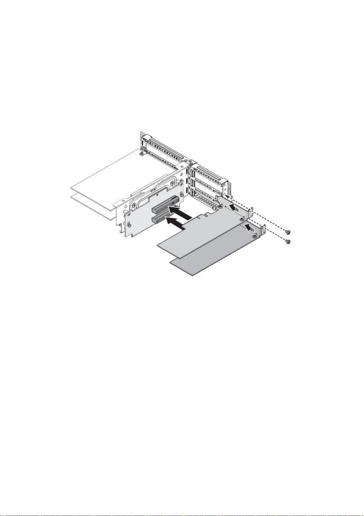
Installing a PCIe Card
To install the PCIe riser card:
1. If a dust cover is present remove the securing screw and slide the dust cover off.
2. Align the new PCIe card with the connector on the riser board and the chassis.
3. Insert the PCIe card and gently press it in place to seat properly.
4. Secure the PCIe card with the provided screw.
Figure 2-24. Remove the PCIe card from board
5. Install the top cover. See
Installing the Top Cover
6. Replace the system in the rack to connect to power.
2-19
on page 2-10.

INSTALLING HARDWARE
E
XPANSION ASSEMBLY
2.9 Expansion Assembly
CAUTION!
E
NSURE
!
ALL
The 2U expansion assembly is designed to support either of these configurations:
One PCIe riser card on slot 1 and two PCIe riser cards on slot 2
Slot 4 supports either PCIe or Mezzanine expansion card
Removing the Expansion Assembly
To remove the expansion assembly:
POWER IS DISCONNECTED FROM THE SYSTEM BEFORE PROCEEDING.
1. Remove the top cover. See
Removing the Top Cover
on page 2-9.
2. Remove the screws securing the expansion assembly to the node.
3. Locate the handle based on the illustration below.
4. Pull out the handle upwards.
Figure 2-25. Expansion the Assembly Handle
5. Unsecure the thumb screws.
2-20

INSTALLING THE
E
XPANSION ASSEMBLY INSTALLING HARDWARE
6. Lift the expansion assembly to remove it from the node.
Figure 2-26. Removing the Expansion Assembly
Installing the Expansion Assembly
To instsall the expansion assembly:
1. Grab the expansion assembly using the handle.
2. Align the expansion assembly to slot 1 and 2.
3. Push the assembly firmly into the expansion slot.
4. Ensure that the screw holes / insertion points are aligned.
2-21

INSTALLING HARDWARE INSTALLING THE
5. Secure the thumb screws.
Figure 2-27. Replacing the Expansion Assembly
E
XPANSION ASSEMBLY
6. Replace the screws that were removed.
7. Replace the handle by pushing it downwards.
Figure 2-28. Replacing the Assembly Handle
2-22

PCI
E
R
ISER BOARD INSTALLING HARDWARE
2.10 PCIe Riser Board
CAUTION!
E
NSURE
!
ALL
The system supports only either a PCIe riser board or a mezzanine board on slot 2. If a
mezzanine board is installed in slot 2, remove the mezzanine board first before installing
the PCIe riser board on slot 2. Refer to
on how to remove the mezzanine board.
Removing the PCIe Riser Board
To remove the PCIe riser board:
POWER IS DISCONNECTED FROM THE SYSTEM BEFORE PROCEEDING.
Removing a Mezzanine Board
on page 2-29 for steps
1. Remove the Expansion Riser Assembly. See
Removing the Expansion Assembly
page 2-20.
Figure 2-29. Remove the Expansion Riser Assembly from the Mainboard
on
2. Remove the screws that attach the PCIe riser board to the riser assembly.
2-23

INSTALLING HARDWARE INSTALLING THE PCI
3. Slide the PCIe board downward to detach it from the 2 securing buttons.
Figure 2-30. Remove the PCIe Riser Board from the Riser Assembly
E
R
ISER BOARD
Installing the PCIe Riser Board
To install the PCIe riser board:
1. Place the PCIe riser board onto the riser assembly, aligning the screws of the board
with the screw holes on the riser assembly.
2. Secure the lock buttons by moving the board upward.
Figure 2-31. Install the PCIe Riser Board to the Riser Assembly
2-24

INSTALLING THE PCI
E
R
ISER BOARD INSTALLING HARDWARE
3. Replace the PCIe board unto the main board.
Figure 2-32. Replace the Expansion Riser Assembly
2-25

INSTALLING HARDWARE MEZZANINE
2.11 Mezzanine
CAUTION!
E
NSURE
!
ALL
The system supports the following mezzanine solutions:
10G LAN mezzanine card
1G LAN mezzanine card
SAS2 6Gbps mezzanine card
Removing a Mezzanine Assembly
1. Remove the system from the rail to disconnect from the power.
POWER IS DISCONNECTED FROM THE SYSTEM BEFORE PROCEEDING.
2. Remove the top cover. See
Removing the Top Cover
on page 2-9.
3. Remove the screw securing the mezzanine assembly to the riser bracket.
4. Lift the cover to remove.
Figure 2-33. Removing the Mezzanine Assembly
5. Remove the securing screws to separate the mezzanine card from the bracket.
2-26

INSTALLING A MEZZANINE ASSEMBLY INSTALLING HARDWARE
6. Remove the bracket and place the mezzanine card in an anti-static bag.
Figure 2-34. Removing Mezzanine Card
Installing a Mezzanine Assembly
1. Remove the new mezzanine card from its packaging. Make sure to hold it by the
edges.
2. Align the mezzanine card with the holes on the bracket and join the two parts
together. Make sure the connector is facing down.
3. Secure with the provided screws.
Figure 2-35. Attaching a Mezzanine Card and Bracket
4. Align the mezzanine assembly with the connector on the riser board and the chassis.
5. Press the mezzanine assembly down to install.
2-27

INSTALLING HARDWARE INSTALLING A MEZZANINE ASSEMBLY
6. Secure the mezzanine assembly with the provided screw.
Figure 2-36. Replacing mezzanine assembly
7. Replace the screws that were removed.
8. Install the top cover. See
Installing the Top Cover
on page 2-10.
9. Replace the system in the rack to connect to power.
2-28

OCP MEZZANINE
B
OARD INSTALLING HARDWARE
2.12 OCP Mezzanine Board
CAUTION!
E
NSURE
!
ALL
Installing an OCP Mezzanine Board
1. Remove the top cover. See
2. Remove the screws securing the OCP bracket to the chassis.
3. Remove the OCP bracket.
POWER IS DISCONNECTED FROM THE SYSTEM BEFORE PROCEEDING.
Removing the Top Cover
on page 2-9.
Figure 2-37. Removing an OCP Bracket
4. Align the I/O ports to the chassis openings.
5. Align the OCP mezzanine board to the standoffs and secure with screws.
Figure 2-38. Installing an OCP Mezzanine Board
2-29

INSTALLING HARDWARE
R
6. Secure the OCP bracket to the chassis with screws.
Figure 2-39. Installing an OCP Bracket
Removing an OCP Mezzanine Board
1. Remove the system from the rail to disconnect from the power.
EMOVING AN OCP MEZZANINE BOARD
2. Remove the top cover. See
Removing the Top Cover
on page 2-9.
3. Remove the screws securing the OCP bracket to the chassis.
4. Remove the OCP bracket.
Figure 2-40. Removing an OCP Bracket
5. Remove the screws securing the OCP mezzanine board to the standoffs.
2-30

R
EMOVING AN OCP MEZZANINE BOARD INSTALLING HARDWARE
6. Lift it up gently then slide it out to clear the I/O ports.
Figure 2-41. Removing an OCP Mezzanine Board
7. Secure the OCP bracket to the chassis with screws.
Figure 2-42. Installing the OCP Bracket
2-31

INSTALLING HARDWARE AIR DUCT
2.13 Air Duct
CAUTION!
E
NSURE
!
ALL
CAUTION!
!
TO PREVENT SYSTEM OVERHEATING, ENSURE THAT THE AIR DUCT IS CLOSED AND PROPERLY SEATED WHEN THE
SYSTEM IS POWERED ON.
Removing the Air Duct
1. Locate the air duct on the chassis.
POWER IS DISCONNECTED FROM THE SYSTEM BEFORE PROCEEDING.
2. Remove the supercap. See
Replacing the SuperCap Power Module (RAID Backup Unit)
on page 2-16.
3. Slide the air duct in the direction of the arrow, and lift up to remove. Refer to the
illustration below.
Figure 2-43. Removing the Air Duct
2-32

INSTALLING THE AIR DUCT INSTALLING HARDWARE
Installing the Air Duct
1. Align the air duct with the notches located next to the fan modules.
2. Slide the air duct until it locks in place.
2-33
Figure 2-44. Installing the Air Duct

INSTALLING HARDWARE PROCESSOR HEAT SINK
2.14 Processor Heat Sink
CAUTION!
E
NSURE
!
ALL
WARNING!
!
The heat sink remains hot after the system has been powered down. Allow sufficient time to
cool before handling system components.
WARNING!
!
The system requires two heat sinks, one over each processor. There are design differences
between the heat sinks, however, the procedure for servicing each heat sink is the same.
For servicing purposes, a single design is used in the following procedures.
To prevent system overheating, ensure that the air duct is closed and properly seated when
the system is powered on.
POWER IS DISCONNECTED FROM THE SYSTEM BEFORE PROCEEDING.
Removing the Processor Heat Sink
To remove the processor heat sink:
1. Remove the system from the rail to disconnect from the power.
2. Remove the top cover. See
3. Loosen captive screws securing the heat sink to the mainboard.
3
Figure 2-45. Removing the heat sink
Removing the Top Cover
2
1
on page 2-9.
4
4. Remove the heat sink.
5. To remove the second processor heat sink, repeat the previous steps.
2-34

INSTALLING THE PROCESSOR HEAT SINK INSTALLING HARDWARE
Installing the Processor Heat Sink
To install the processor heat sink:
1. Align the heat sink over the processor plate.
2. Align the screws with the screw posts on the mainboard.
2
4
3
1
Figure 2-46. Installing the heat sink
3. Tighten the screws.
4. To install the second processor heat sink, repeat the previous steps.
5. Install the top cover. See
2-35
Installing the Top Cover
on page 2-10.

INSTALLING HARDWARE PROCESSOR
2.15 Processor
Note:
All the instructions and images in this section are for illustration purposes only and may not
reflect the actual product.
CAUTION!
E
!
NSURE
WARNING!
!
The processor remains hot after the system has been powered down. Allow sufficient time to
cool before handling system components.
ALL
POWER IS DISCONNECTED FROM THE SYSTEM BEFORE PROCEEDING.
Removing the Processor
To remove the processor:
1. Pull the system out of the rack to disconnect from power.
2. Remove the top cover. See
3. Remove the processor heat sink. See
Removing the Top Cover
Removing the Processor Heat Sink
on page 2-9.
on page 2-34.
4. Push the locking lever down and in to unlock the load plate.
Figure 2-47. Unlocking the locking lever
5. Push the release lever down and in to release the load plate.
Figure 2-48. Unlocking the locking lever
2-36

INSTALLING THE PROCESSOR INSTALLING HARDWARE
6. Lift the load plate upright.
Figure 2-49. Lifting Processor Load Plate
7. Remove the processor.
Figure 2-50. Removing the processor
8. To remove the second processor, repeat the previous steps.
CAUTION!
!
AVOID CONTACT WITH
ANY
THERMAL GREASE ON THE PROCESSOR.
Installing the Processor
1. Push the locking lever down and in to unlock the load plate.
2. Push the release lever down and out to release the load plate.
3. Lift the load plate upright.
4. If there is a processor dust cover, remove it at this time.
5. Remove the new processor from its packaging. Make sure to hold the processor by
the sides. Do NOT touch the underside of the processor.
2-37

INSTALLING HARDWARE INSTALLING THE PROCESSOR
6. Align the triangle identifying pin 1 of the processor with the triangular cutout on
the socket.
7. Locate the pin1 (A) on processor and the pin1 (B) corner of the socket.
8. Locate the indents (C) on processor and corresponding tab (D) on socket.
9. Install the processor.
Figure 2-51. Installing the processor
Note:
Use the socket cover to protect the socket when the socket is empty.
10. Lower the processor load plate over the processor, and secure the locking levers to
lock the processor in place.
Figure 2-52. Securing the processor
11. To install the second processor, repeat the previous steps.
12. Install the processor heat sink. See
13. Install the top cover. See
Installing the Top Cover
Installing the Processor Heat Sink
on page 2-10.
14. Replace the system in the rack.
on page 2-35.
2-38

Table 3: DDR4 Registered Maximum Frequency Support (per channel)
MEMORY MODULES INSTALLING HARDWARE
TYPE
R
ANK PER
DIMM
AND
DATA
WIDTH
DIMM CAPACITY
(GB)
SPEED (MT/S);
V
OLTAGE (V); SLOT P
ER
CHANNEL (SPC) AND
DIMM PER CHANNEL (DPC)
1 SLOT P
ER
CHANNEL
2 SLOT P
ER
CHANNEL
3 SLOT PER CHANNEL
1DPC
1DPC
2DPC
1DPC
2DPC
3DPC
4GB
8GB
1.2V
1.2V
1.2V
1.2V
1.2V
1.2V
RDIMM
SR x 4
8GB
16GB
2133
2133
1866
2133
1866
1600
RDIMM
SR x 4
4GB
8GB
2133
2133
1866
2133
1866
1600
RDIMM
DR x 8
8GB
16GB
2133
2133
1866
2133
1866
1600
RDIMM
DR x 8
16GB
32GB
2133
2133
1866
2133
1866
1600
LRDIMM
QR x 4
32GB
64GB
2133
2133
2133
2133
2133
1600
LRDIMM 3DS*
8R x 4
64GB
128GB
2133
2133
2133
2133
2133
1600
* Grantley intercept at platform refresh (Boardwell).
2.16 Memory Modules
WARNING!
!
Mainboard is supplied with all DIMM slots populated with dummy DIMMs for proper air flow.
When installing and replacing memory modules, only remove those dummy DIMMs that are
to be directly replaced. All DIMM slots must be occupied at all times by either a memory mod-
ule or dummy DIMM.
General Guidelines
All servers have specific rules for population of memory on the mainboard. Refer to the
following individual server rules for information on how to populate the particular server
required.
Memory Population Support
2-39

INSTALLING HARDWARE
R
EMOVING A MEMORY MODULE
Removing a Memory Module
CAUTION!
!
HANDLE THE MEMORY MODULE
WARNING!
!
1. Remove the top cover. See
2. Press down on the two ejector levers (A) at both ends of the DIMM slot. The memory
3. Hold the DIMM module by the ends and remove it from the system. Place the DIMM
Memory modules remain hot after the system is powered down. Allow sufficient time for the
memory modules to cool before handling system components.
module partially ejects.
module in an atistatic packaging.
BY
THE EDGES AT
Removing the Top Cover
ALL
TIMES.
on page 2-9.
A
A
Figure 2-53. Removing a Memory Module
2-40

INSTALLING A MEMORY MODULE INSTALLING HARDWARE
Installing a Memory Module
CAUTION!
!
1. Locate the DIMM slot to populate and open the ejector levers (A) at both ends of the
2. Align the notch on the DIMM module with the protrusion on the slot.
3. Press down on both corners of the DIMM module until the ejector levers lock in
HANDLE THE MEMORY MODULE
DIMM slot.
place.
A
BY
THE EDGES AT
ALL
TIMES.
Figure 2-54. Installing Memory Module
4. Install the top cover. See
notch
protrusion
A
Installing the Top Cover
on page 2-10.
2-41

INSTALLING HARDWARE MAINBOARD
2.17 Mainboard
CAUTION!
E
NSURE
!
ALL
Removing the Mainboard
1. Remove the rear top cover. See
POWER IS DISCONNECTED FROM THE SYSTEM BEFORE PROCEEDING.
Removing the Top Cover
on page 2-9.
2. Remove the air duct. See
Removing the Air Duct
3. Disconnect all cabling from the mainboard.
4. Remove the memory modules. See
5. Remove the processor heat sinks. See
Removing a Memory Module
Removing the Processor Heat Sink
34.
6. Remove the processors. See
7. Remove the PCI riser assembly. See
Removing the Processor
Removing the Expansion Assembly
8. Loosen the thumbscrews.
Figure 2-55. Remove screws from mainboard
on page 2-32.
on page 2-40.
on page 2-
on page 2-36.
on page 2-20.
9. Remove the mainboard from the chassis.
10. Place the mainboard in an anti-static bag.
2-42

INSTALLING THE MAINBOARD INSTALLING HARDWARE
Installing the Mainboard
1. Remove the mainboard from its anti-static protective package.
2. Align the thumbscrews of the mainboard to the screw holes on the node.
3. Secure the mainboard to the chassis with the provided screws.
Figure 2-56. Install screws on mainboard
4. Install the PCI riser assembly. See
5. Install the processors. See
6. Install the heat sinks. See
Installing the Processor
Installing the Processor Heat Sink
7. Install the memory modules. See
Installing the Expansion Assembly
on page 2-37.
on page 2-35.
Installing a Memory Module
on page 2-41.
8. Connect all cabling previously disconnected from the mainboard.
9. Install the air duct. See
10. Install the rear top cover. See
Installing the Air Duct
Installing the Top Cover
on page 2-33.
on page 2-10.
on page 2-21.
2-43

INSTALLING HARDWARE HARD DISK D
RIVE
B
ACKPLANE
2.18 Hard Disk Drive Backplane
CAUTION!
E
NSURE
!
ALL
Locating the HDD Backplane
The system has one (1) HDD backplane (A) located in between the back of the hard disk
drives and fan module. Refer to the following illustration for the location of the backplane.
POWER IS DISCONNECTED FROM THE SYSTEM BEFORE PROCEEDING.
A
Figure 2-57. HDD Backplane Location (2.5” System)
A
Figure 2-58. HDD Backplane Location (3.5” System)
2-44

R
EMOVING THE BACKPLANE (2.5”) INSTALLING HARDWARE
Removing the Backplane (2.5”)
This procedure only applies to the backplane in the 2.5” system.
1. Remove the top cover. See
2. Remove the middle top cover. See
3. Remove the expander board. See
Removing the Top Cover
Removing the Middle Top Cover
Removing an Expander Board
on page 2-9.
on page 2-58.
4. Remove the securing screw(s) from the HDD backplane assembly.
5. Remove the assembly from the chassis.
on page 2-11.
Figure 2-59. Removing the HDD Backplane Assembly Screws
6. Remove the securing screw(s) from the HDD backplane.
7. Remove the HDD backplane.
Figure 2-60. Removing the HDD Backplane Screws
2-45

INSTALLING HARDWARE INSTALLING THE
Installing the Backplane (2.5”)
This procedure only applies to the backplane in the 2.5” system.
B
ACKPLANE (2.5”)
1. Remove the top cover. See
2. Remove the middle top cover. See
Removing the Top Cover
Removing the Middle Top Cover
on page 2-9.
on page 2-11.
3. Align the HDD backplane screw hole(s) with the screw well(s) on the HDD back-
plane bracket.
4. Secure the HDD backplane to the bracket with screw(s).
Figure 2-61. Aligning the HDD Backplane
5. Align the HDD backplane assembly screw hole(s) with the screw well(s) on the chas-
sis.
6. Secure the assembly to the chassis with screw(s).
Figure 2-62. Aligning the HDD Backplane Assembly
2-46

R
EMOVING THE HDD BACKPLANE (3.5”) INSTALLING HARDWARE
Removing the HDD Backplane (3.5”)
This procedure only applies to the backplane in the 3.5” system.
To remove the HDD backplane:
1. Remove the top cover. See
2. Remove the fan modules. See
Removing the Top Cover
Removing the Fan Module
3. Disconnect all cables from the HDD backplane.
4. Loosen the thumbscrews.
Figure 2-63. Removing the HDD Backplane Screws
on page 2-9.
on page 2-13.
5. Remove the backplane from the chassis.
2-47

INSTALLING HARDWARE INSTALLING THE HDD
Installing the HDD Backplane (3.5”)
This procedure only applies to the backplane in the 3.5” system.
Note:
HDD backplanes must be installed before installing any HDDs.
To install the HDD backplane:
1. Align the HDD backplane screw holes with the screw well on the chassis.
Figure 2-64. Aligning the HDD Backplane
B
ACKPLANE (3.5”)
2. Secure the HDD backplane to the chassis with the provided screws.
3. Connect all cables that were disconnected from the HDD backplane.
4. Install the fan modules. See
5. Install the top cover. See
Installing the Fan Module
Installing the Top Cover
on page 2-14.
on page 2-10.
2-48

SSD AIR DUCT INSTALLING HARDWARE
2.19 SSD Air Duct
The solid state disk assembly type depending on your systems.
CAUTION!
E
NSURE
!
ALL
Removing the SSD Air Duct
1. Remove the top cover. See
2. Remove the SSD air duct by lifting it up.
2-49
POWER IS DISCONNECTED FROM THE SYSTEM BEFORE PROCEEDING.
Removing the Top Cover
on page 2-9.
Figure 2-65. Removing the SSD Air Duct

INSTALLING HARDWARE INSTALLING THE SSD AIR DUCT
Installing the SSD Air Duct
1. Align and install the SSD air duct.
Figure 2-66. Installing the SSD Air Duct
2. Install the top cover. See
Installing the Top Cover
on page 2-10.
2-50

SSD FAN MODULE INSTALLING HARDWARE
2.20 SSD Fan Module
The solid state disk assembly type depending on your systems.
CAUTION!
E
NSURE
!
ALL
Removing a SSD Fan Module
1. Remove the top cover. See
POWER IS DISCONNECTED FROM THE SYSTEM BEFORE PROCEEDING.
Removing the Top Cover
on page 2-9.
2. Remove the SSD air duct. See
Removing the SSD Air Duct
on page 2-49.
3. Disconnect the fan cabling from the SSD backplane assembly.
Figure 2-67. Disconnect the Cabling
4. Pull the fan module up to remove from the SSD fan cage.
2-51
Figure 2-68. Removing the Fan Assembly

INSTALLING HARDWARE INSTALLING A SSD FAN MODULE
Installing a SSD Fan Module
1. Connect the fan cabling to the SSD backplane assembly.
Figure 2-69. Connect the Cabling
2. Align the fan modules with the bracket. Make sure the positioning arrows are facing
the rear of the chassis.
3. Install the fan module in the cage.
Figure 2-70. Installing the Fan Assembly
4. Install the SSD air duct. See
5. Install the top cover. See
Installing the Top Cover
Installing the SSD Air Duct
on page 2-10.
on page 2-50.
2-52

SSD
B
ACKPLANE INSTALLING HARDWARE
2.21 SSD Backplane
The solid state disk assembly type depending on your systems.
CAUTION!
E
NSURE
!
ALL
Removing a SSD Backplane
1. Remove the top cover. See
POWER IS DISCONNECTED FROM THE SYSTEM BEFORE PROCEEDING.
Removing the Top Cover
on page 2-9.
2. Remove the SSD air duct. See
3. Remove the SSD modules. See
4. Remove the SSD fan modules. See
Removing the SSD Air Duct
Removing the SSD Module
Removing a SSD Fan Module
5. Remove the fan cage from the chassis.
on page 2-49.
on page 2-4.
on page 2-51.
2-53
Figure 2-71. Removing the SSD Fan Cage

INSTALLING HARDWARE
6. Disconnect the cabling from the SSD backplane assembly.
Figure 2-72. Disconnect the Cabling
R
EMOVING A SSD BACKPLANE
7. Remove the securing screw(s) from the SSD backplane assembly.
8. Remove the assembly from the chassis.
Figure 2-73. Removing the SSD Backplane Assembly
9. Remove the securing screw(s) from the SSD backplane.
2-54

INSTALLING A SSD
B
ACKPLANE INSTALLING HARDWARE
10. Remove the SSD backplane.
Figure 2-74. Removing the SSD Backplane
Installing a SSD Backplane
1. Position the backplane so that the PCIe connectors face the inside of the bracket.
The rear of the backplane includes the cabling connectors, and it faces the fan modules.
2. Align the SSD backplane in the bracket. Make sure the holes on the backplane are
aligned with the holes on the bracket.
3. Secure the SSD backplane to the bracket with screw(s).
Figure 2-75. Aligning the SSD Backplane
4. Secure the SSD backplane to the bracket with the screws.
2-55

INSTALLING HARDWARE INSTALLING A SSD
5. Secure the SSD backplane assembly to the chassis with screw(s).
Figure 2-76. Installing the SSD Backplane Assembly
B
ACKPLANE
6. Connect the cabling to the backplane.
Figure 2-77. Connect the Cabling
2-56

INSTALLING A SSD
B
ACKPLANE INSTALLING HARDWARE
7. Align the holes on the fan cage align th e pins on the chassis.
8. Install the fan cage.
Figure 2-78. Removing the SSD Fan Cage
9. Install the SSD fan modules. See
10. Install the SSD modules. See
11. Install the SSD air duct. See
12. Install the top cover. See
Installing the SSD Module
Installing the SSD Air Duct
Installing the Top Cover
Installing a SSD Fan Module
on page 2-5.
on page 2-50.
on page 2-10.
on page 2-52.
2-57

INSTALLING HARDWARE
2.22 Expander Board
Removing an Expander Board
The expander board is only available on the 2.5” model.
CAUTION!
E
NSURE
!
1. Remove the top cover. See
ALL
POWER IS DISCONNECTED FROM THE SYSTEM BEFORE PROCEEDING.
Removing the Top Cover
on page 2-9.
E
XPANDER BOARD
2. Remove the middle top cover. See
Removing the Middle Top Cover
on page 2-11.
3. Remove the securing screw(s) from the expander board.
4. Slide the board towards the rear of the system to release it from the retention pins.
5. Remove the HDD backplane from the chassis.
Figure 2-79. Removing the Expander Board Screws
2-58

INSTALLING AN
E
XPANDER BOARD INSTALLING HARDWARE
Installing an Expander Board
The expander board is only available on the 2.5” model.
CAUTION!
E
NSURE
!
1. Remove the top cover. See
ALL
POWER IS DISCONNECTED FROM THE SYSTEM BEFORE PROCEEDING.
Removing the Top Cover
on page 2-9.
2. Remove the middle top cover. See
Removing the Middle Top Cover
on page 2-11.
3. Align the expander board with the retention pins on the chassis.
4. Install the expander board and make sure the retention pins are seated correctly in
place.
5. Slide the expander board towards the front of the system.
6. Secure the HDD backplane to the chassis with screw(s).
Figure 2-80. Aligning the Expander Board
7. Connect the cabling on the expander board.
2-59

INSTALLING HARDWARE FRONT PANEL
2.23 Front Panel Board
CAUTION!
E
NSURE
!
ALL
The front panel board located at the left side of the rack can be removed and installed.
Removing the Front Panel Board
To remove the front panel board:
1. Push down the securing clips from the back of the right handle of the rack. A flat
screw driver can be used to do this.
2. Ensure that this is done for both top and bottom part of the cover.
Figure 2-81. Location of Clips, Front Control Board (Left Side)
POWER IS DISCONNECTED FROM THE SYSTEM BEFORE PROCEEDING.
B
OARD
2-60

INSTALLING THE FRONT PANEL
B
OARD INSTALLING HARDWARE
3. Remove the outermost cover.
Figure 2-82. Removing the Cover
4. Remove the screws and connecting cable on the front panel board.
5. Detach the front panel board.
Figure 2-83. Removing the Front Control Board
Installing the Front Panel Board
To install the front panel board:
1. Place the front panel board at the right side handle of the rack.
2-61

INSTALLING HARDWARE INSTALLING THE FRONT PANEL
2. Replace the screws and connect the cable.
Figure 2-84. Replacing FCP
B
OARD
3. Replace the outermost cover.
Figure 2-85. Replace the FCP Cover
4. Ensure that the cover fits snugly on the handle.
2-62

USB
B
OARD INSTALLING HARDWARE
2.24 USB Board
CAUTION!
E
NSURE
!
ALL
The USB modules located at the right side of the rack can be removed and installed.
Removing the USB Board
To remove the USB board:
1. Push down the securing clips from the back of the right handle of the rack. A flat
screw driver can be used to do this.
2. Ensure that this is done for both top and bottom part of the cover.
Figure 2-86. Location of Clips, Front USB Board (Right Side)
2-63
POWER IS DISCONNECTED FROM THE SYSTEM BEFORE PROCEEDING.

INSTALLING HARDWARE
3. Remove the outermost cover.
Figure 2-87. Removing the cover
R
EMOVING THE USB BOARD
4. Remove the screws and connecting cable on the USB board.
5. Detach the USB board.
Figure 2-88. Removing the USB board
2-64

INSTALLING THE USB
B
OARD INSTALLING HARDWARE
Installing the USB Board
To install the USB board:
1. Place the USB board at the right side handle of the rack.
2. Replace the screws and connect the cable.
Figure 2-89. Securing the USB Board
3. Align the outer cover with the USB board
Figure 2-90. Aligning the Outer Cover with the USB Board
2-65
 Loading...