

Page 1
User Manual / 用户手册
Page 2

English .............................................................................................................................................................
中文 ..................................................................................................................................................................
Languages 语言
1-25
26-49
Page 3
Specifications & Configuration & Box Contents ...........................................................................
Aircraft Parts .................................................................................................................................
Before Assemble the Aircraft ........................................................................................................
Flight Control .................................................................................................................................
Flight Mode ...................................................................................................................................
Flight Control Configuration ...........................................................................................................
Transmitter Calibration ................................................................................................................
Flight Control Calibration..................................................................................................................
Difference between Beginner Mode and Experienced Mode .......................................................
Control Direction Test & Flight Control Correction Test ..............................................................
Parameter Setup Button ............................................................................................................
External Parameter Setup Unit ..................................................................................................
Control Direction / Mode Switch / Throttle Cut Switch Test .........................................................
Troubleshooting Guide ...............................................................................................................
Assemble the Aircraft ...................................................................................................................
Install the Horizontal Tail ............................................................................................................
Install the Flight Battery & Center of Gravity (CG) ....................................................................
Pre-Flight Checklist & Flying Checklist ....................................................................................
Transmitter Control Direction .....................................................................................................
Parts Listing ..............................................................................................................................
EN
Safety Precautions and Warnings
RC aircraft is controlled by radio signals. It may be interfered by other radio signals during operation. These
interference may cause the aircraft lose control.
1. Improper operation to ESKY EYAS may lead to damage or loss. lt is prohibited for children
under 14 years to operate this product.
2. Keep it away from high temperature environment for storage and flight.
3. Suggested operation temperature: 5-35°C , Humidity: 20-80%.
4. Keep away from fan, air conditioner, table light while flying.
5. Do not contact the motor in case of damage or injury.
1. Keep away from crowds in case of accidents.
2. Do not operate ESKY EYAS in shower room or under rain. Moisture may go inside the
aircraft which may cause electronic parts malfunction and unexpected incident.
3. Do not re-equip or repair your aircraft with unauthorized parts.
4. Keep people and objects away from the spinning unit and parts in case of damage or
injury.
Table of Contents
11-13
19-20
23-24
3
4
5-7
8
9
9-10
13
14
14
15
16
17
18
20
21
22
25
2
Page 4
Specifications
Flying Time ............................................
Main Material ..................................................
Battery Connector ...........................................
Flight Control .......................
Battery Charger .................
Transmitter / Receiver .........
EN
Wing Span .................................................
Length .........................................................
Flying Weight .................................................
Configuration
Motor ..............
ESC ...................................................
Servo .......................................
Battery ................................
2306-2250Kv Brushless Outrunner
30A BEC 3A
8g Digital Servo x 4
Required to Complete
(3S 2200mAh 20C)
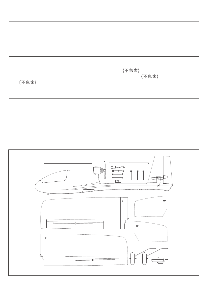
Box Contents
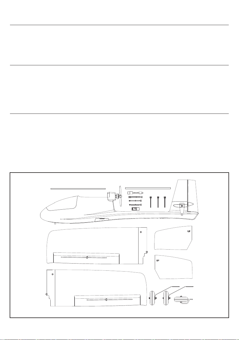
1 x Fuselage Set
1 x Left Wing
1 x Right Wing
1 x Left Horizontal Tail
1 x Right Horizontal Tail
3 x Receiver Wires
1 x Multi-Function Control Unit
1100mm
871mm
755g
15 Minutes
EPO
XT60
ESKY 3/6 Axis Gyro
Required to Complete
(2S/3S Balance Charger)
Required to Complete
(6CH or above)
1 x Wing Carbon Fiber Tube
1 x Horizontal Tail Carbon Fiber Tube
1 x Nose Gear
2 x Main Landing Gear
3 x Wing Fixing Bolt
1 x USB Data Cable
3
Page 5
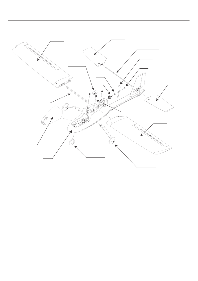
Aircraft Parts
EN
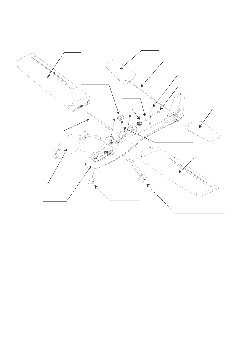
Wing
Carbon Fiber Tube
Cabin Cover
Fuselage
Right Wing
Flight Control
Right Horizontal Tail
Washer
Motor
Nose Gear
Horizontal Tail
Carbon Fiber Tube
Props
Nut
Left Horizontal Tail
Wing Fixing Bolt
Left Wing
Main Landing Gear
4
Page 6
EN
Before Assemble the Aircraft
The Esky EYAS FC INSIDE does not come with a transmitter, receiver, charger and flight battery. Customers
need to prepare them on their own. The recommended transmitter should have six channels or more, with two
or more two-position or three-position switches. Before connecting the receiver to the flight control, please
ensure the power supply voltage and connection wire sequence of the receiver to avoid damage to the
receiver or flight controller due to improper operation. Before assembling the aircraft, the transmitter should be
bound to a receiver, and the receiver should be connected to the corresponding plug on the flight control using
the receiver connection wire.
If using a smart remote controller (with a screen and settings function), a new mode is required to be created,
and it is recommended to select the aircraft model (fixed-wing model with a normal tail).
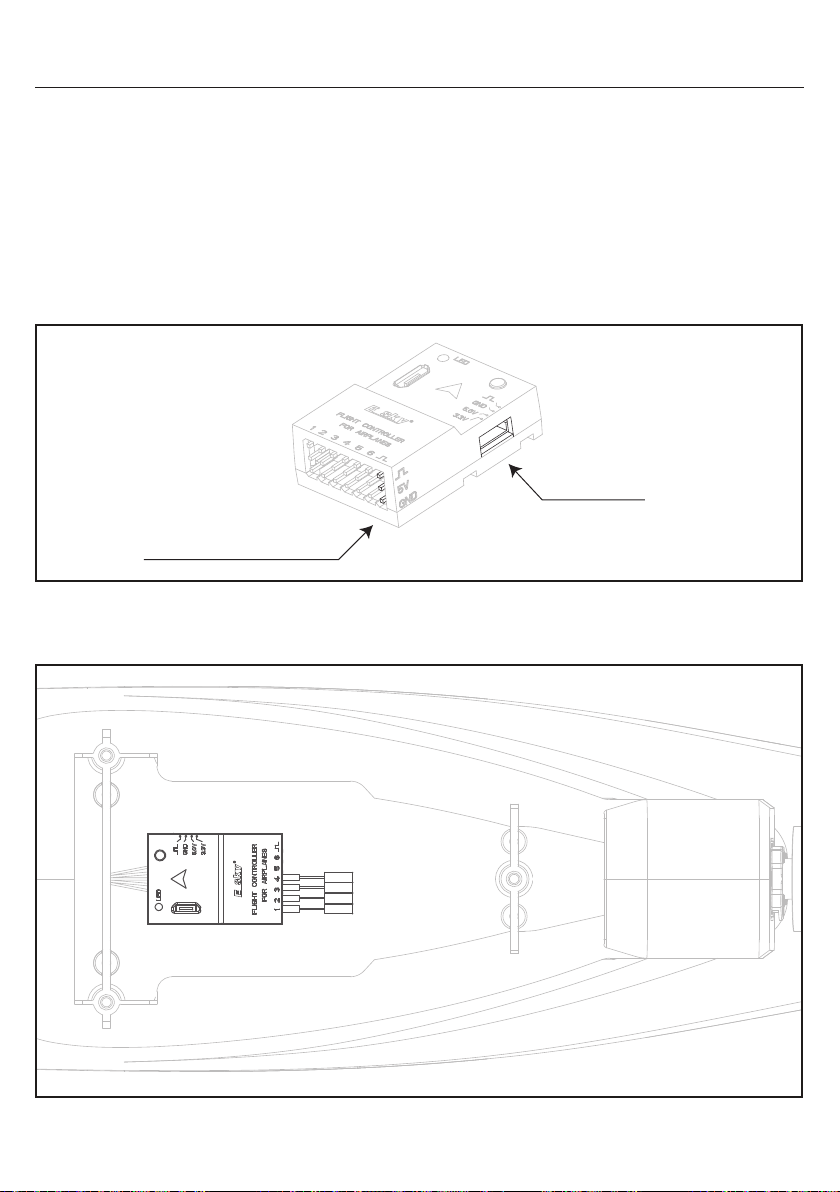
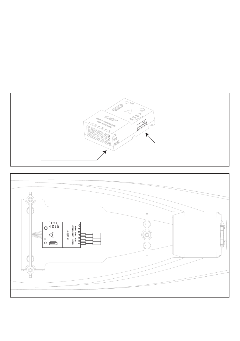
Receiver Port
5V Receiver Port (JR Plug)
The compatible input signals for the Esky flight control are: PPM, SBUS, DSM, DSM\SRXL2, IBUS, CRSF.
The installation position of the flight controller is shown in the diagram below.
Rudder
Throttle
Elevator
Aileron
5
Page 7
Before Assemble the Aircraft
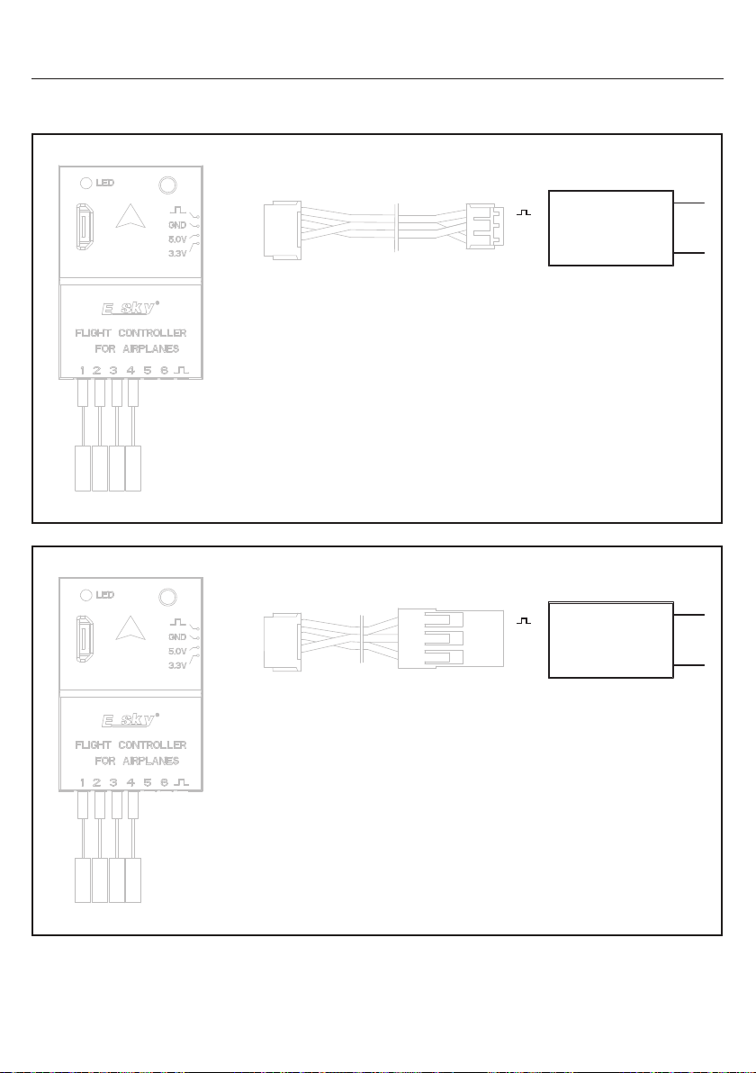
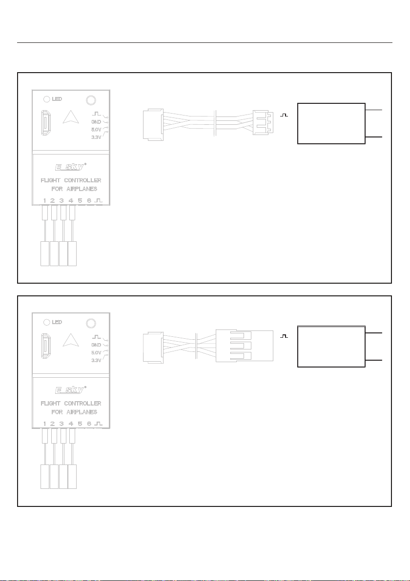
The connections between various receivers and flight control are as follows:
Orange
Black
Red
ZH4Y to ZH3Y
5V Receiver Connection Wire
Elevator
Throttle
Rudder
Aileron
GND
5V
EN
5V Receiver
Elevator
Aileron
Throttle
Rudder
Orange
Black
Red
5V Receiver Connection Wire
ZH4Y to JR
6
5V
GND
5V Receiver
Page 8
Before Assemble the Aircraft
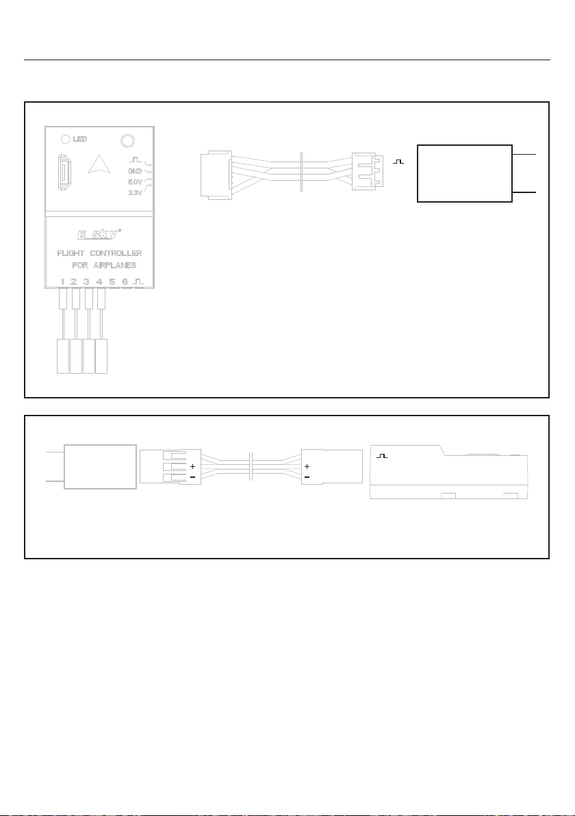
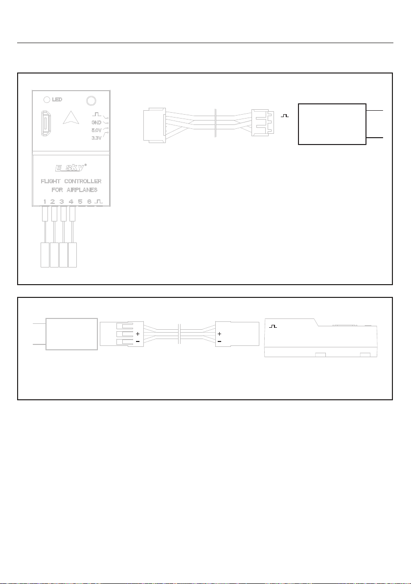
The connections between various receivers and flight control are as follows:
White
Black
Red
GND
3.3V Receiver
3.3V
EN
Elevator
Throttle
Rudder
Aileron
5V Receiver
3.3V Receiver Connection Wire
ZH4Y to ZH3Y
SS
JR to JR
5V Connection Wire
(Not Included)
5V
GND
7
Page 9
Flight Control
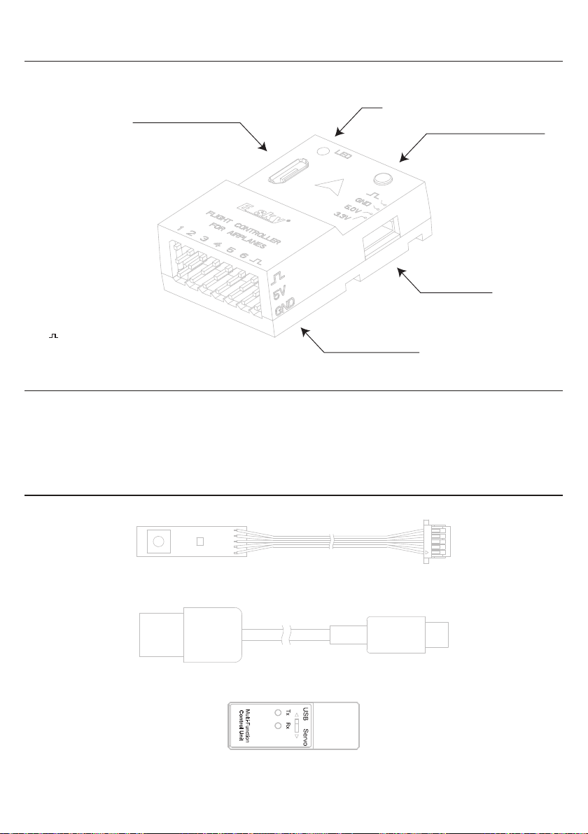
Weight .............................................................
Input Voltage ...............................................
Output PWM ........................................
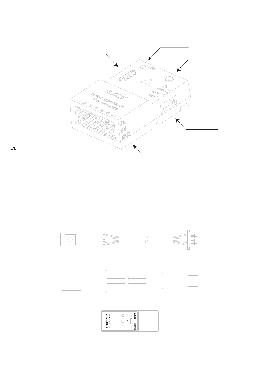
Parameter Setup Port
1 - Aileron
2 - Elevator
3 - Throttle
4 - Rudder
5 - Aux 1
6 - Aux 2
- 5V Receiver Port (JR Plug)
Specifications
EN
LED
Parameter Setup Button
Receiver Port
Channel Pin Order
Length .......................................................
Width .........................................................
Height ..........................................................
Flight Control Parts
External Parameter Setup Wire (Installed in the Aircraft)
36.2mm
24.4mm
12mm
USB Cable
Multi-Function Control Unit
8
7.8g
5V±0.5
6 Channels
Page 10
EN
Flight Mode
There are two modes available for the flight control:
Beginner Mode (6-axis mode) and experienced mode (3-axis mode)
Beginner Mode (6-axis mode): To prevent over-control and mitigate the risk of orientation loss and crashes,
pitch and bank angle limits are in place. Additionally, when the control sticks are released, the airplane
automatically returns to level flight, ensuring a safe and stable flying experience.
Experienced mode (3-axis mode): There are no restrictions on pitch or bank angles, providing you with full
control over the aircraft! 3 Axis Mode operates in the background to enhance stability by minimizing the impact
of wind and turbulence. This results in a controlled and immersive flying experience, giving you the sensation
of piloting a larger aircraft.
Caution: Flight mode switching is assigned to channel 5 of the transmitter using 2 or 3 position switches.
Channel 6 of the transmitter is used for throttle cut using 2 or 3 position switches and these setting CANNOT
be changed. The "Aux1" and "Aux2" channels on the flight control can be assigned to channels other than 1-6
for controlling flaps or retracting landing gear.
Flight Control Configuration
Caution: Before performing the following steps, please ensure that the transmitter is turned on.
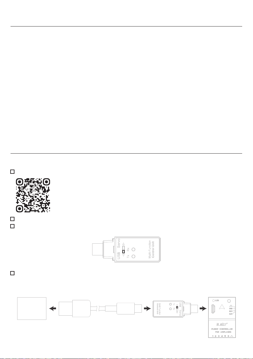
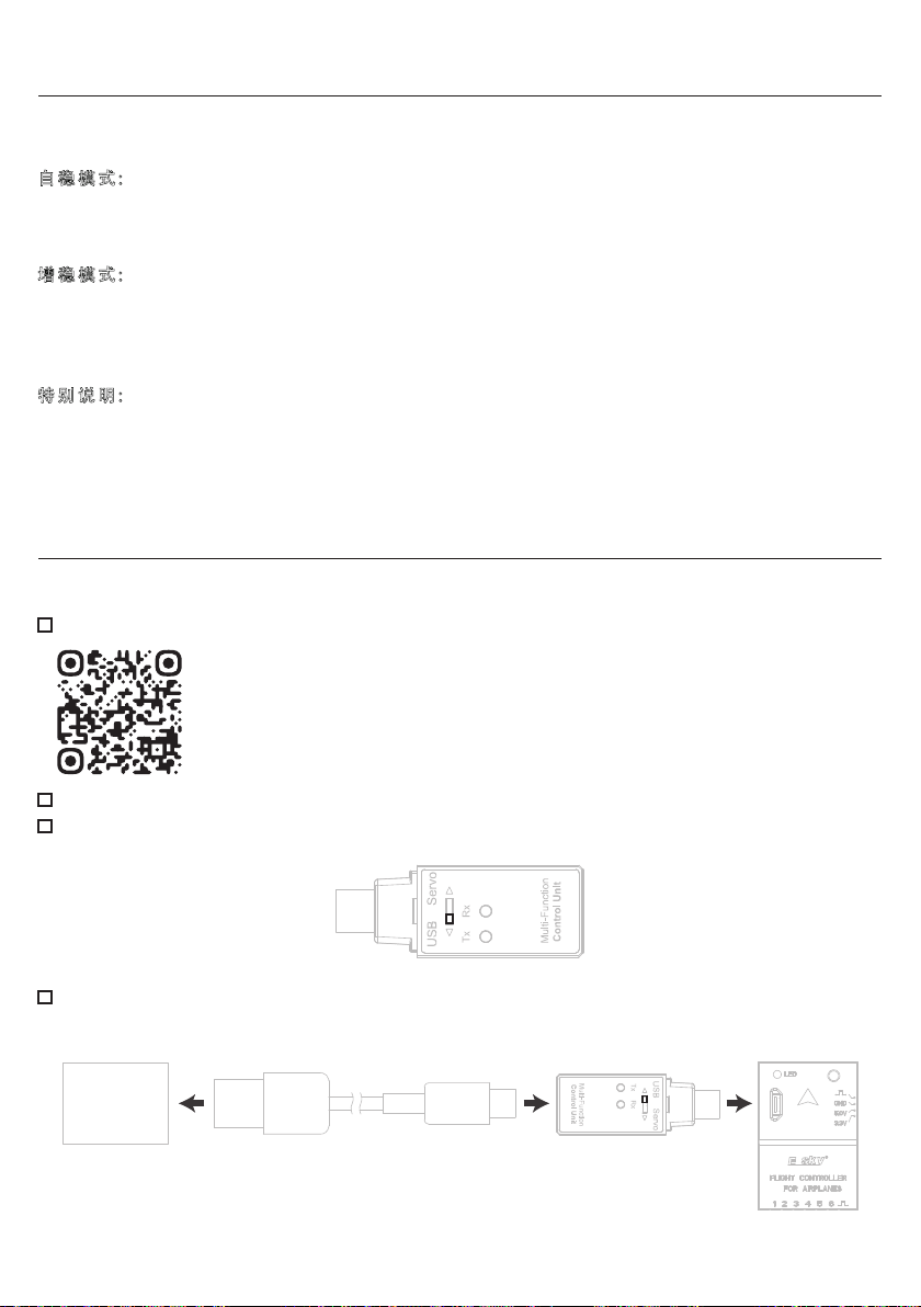
Download the FXZ Configurator through the following QR code.
https://esky-rc.com/manual/detail/2
Double-click the FXZ Configurator logo to open the flight control configuration software.
Adjust the toggle switch on the multi-function control unit to the USB end. Refer to the diagram below.
Connect the flight control and multi-function control unit to the computer as shown in the diagram below.
The configuration software will automatically detect and connect to the flight control. If it doesn't
automatically connect, select the correct serial port and click on the "Connect" button.
Micro USB Plug
Computer
9
Page 11
EN
Flight Control Configuration
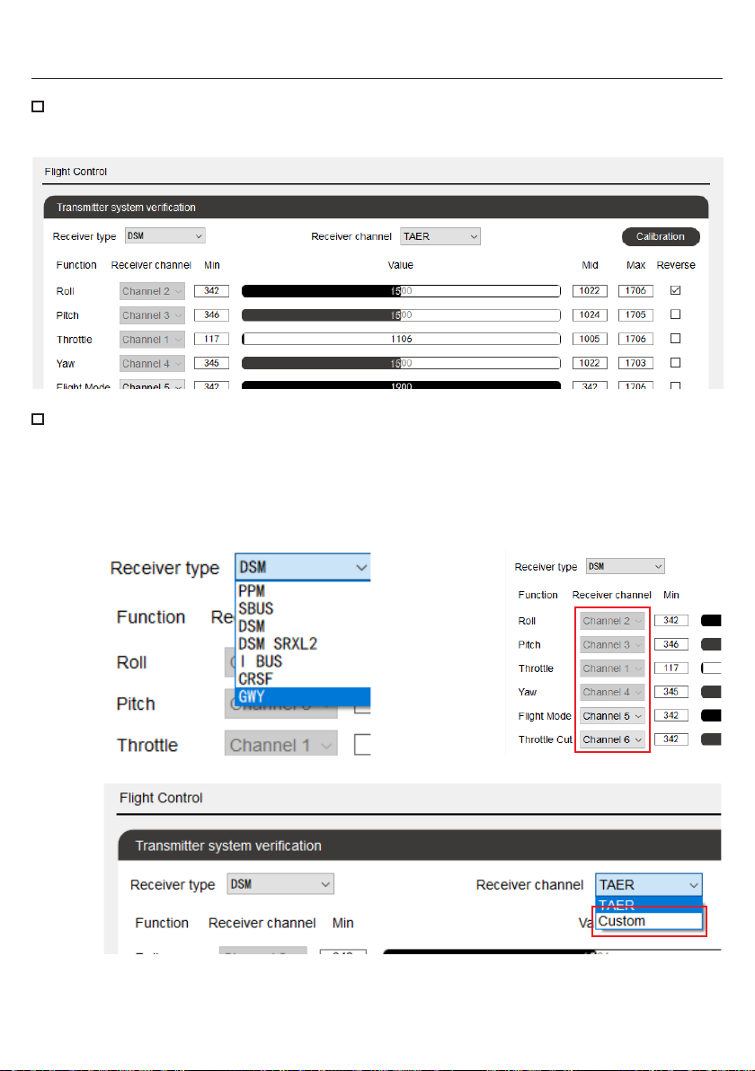
Once the configuration software interface displays "Flight Control" and "Attitude" in the bottom left corner,
click on "Flight Control" to enter the "Flight Control System" interface.
Please refer to figure 1 to select the correct receiver protocol based on the type of receiver being used. The
system will automatically match the channel order according to the selected receiver protocol, with the first
four channels displayed in gray and cannot be modified, as shown in figure 2. To change the default channel
order, select "Custom" on the right side of the "Receiver Channels" column, as shown in figure 3. All
channels can be matched according to your needs, as shown in figure 3. Click the "Save" button to save
the settings, it will displays "Save successful" and reverts back to "Save" to finish the setting.
Figure 1
Figure 3
Figure 2
10
Page 12
EN
Transmitter Calibration
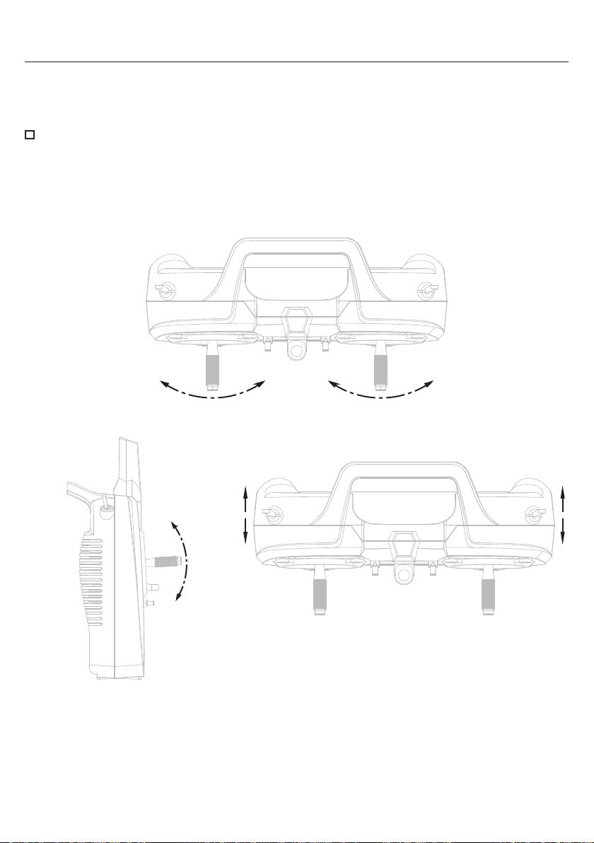
The calibration procedure for the transmitter is as follows:
Before starting the calibration of the transmitter, please adjust the trims of each channel to the neutral position.
The following instructions are provided with the left hand throttle (Mode 2) as an example.
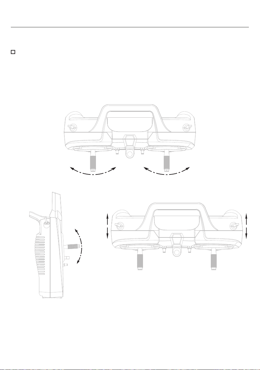
Calibration: Click the "Start Calibration" button in the top right corner of the software. Move the sticks in a +
shape moving from left to right, (as shown in figure 1) then up and down.(as shown in figure 2) Press gently
on the sticks at the stops to achieve an accurate calibration. Return both sticks to the center position. Set
the 2-position switches corresponding to channels 5 and 6 to the maximum and minimum positions (as
shown in figure 3).Then click the "Complete Calibration" button and wait for the system update to finish the
transmitter calibration.
Figure 1
Figure 2 Figure 3
11
Page 13
EN
Transmitter Calibration
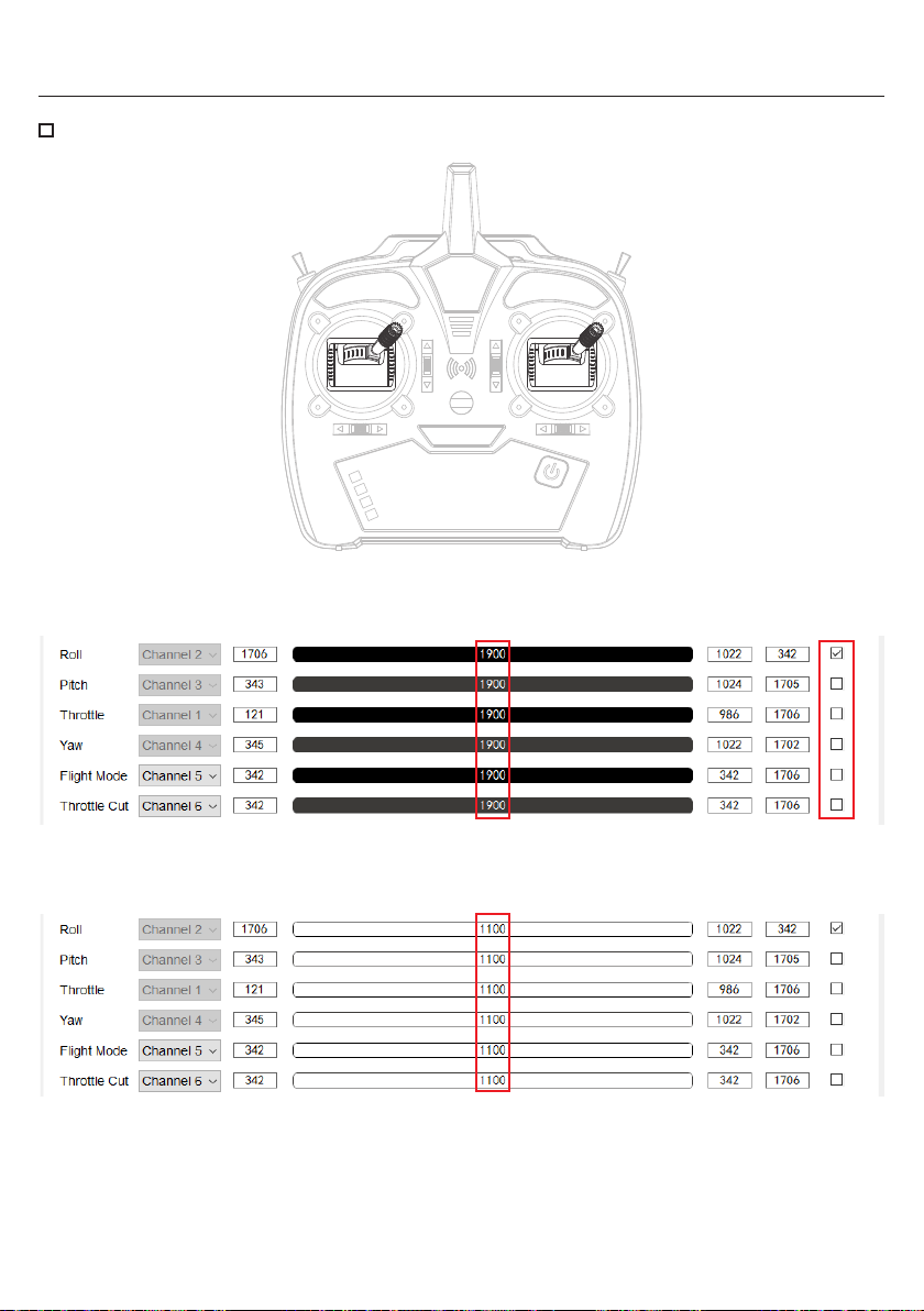
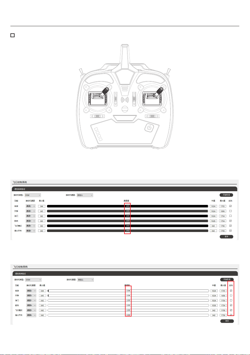
Channel Direction: Move both sticks to the top right corner and press gently on the sticks at the stops.
The values for channels 1, 2, 3, and 4 should be around 1900. If the values are around 1100, click the
"Reverse" checkbox on the right to reverse the direction and click "Save" to finish the direction setting.
When moving both sticks to the bottom left corner, the values for channels 1, 2, 3, and 4 should be around
1100.
12
Page 14
EN
Transmitter Calibration
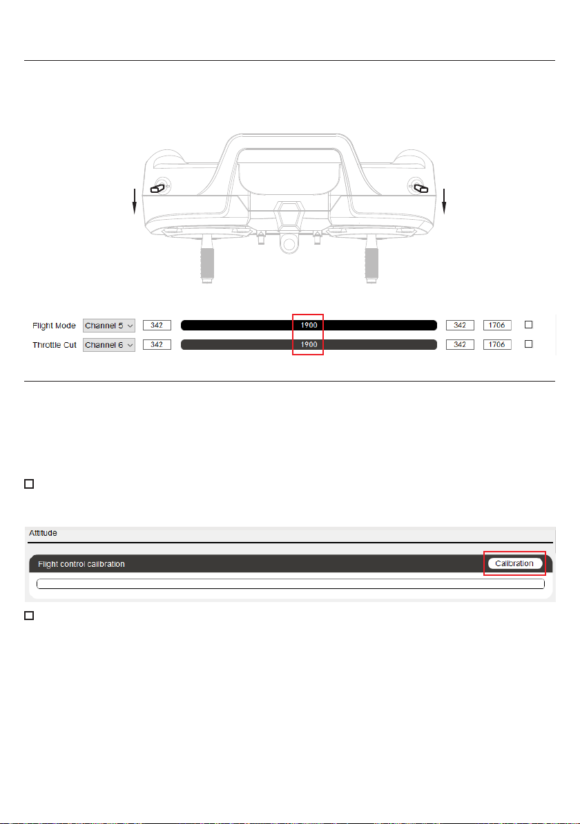
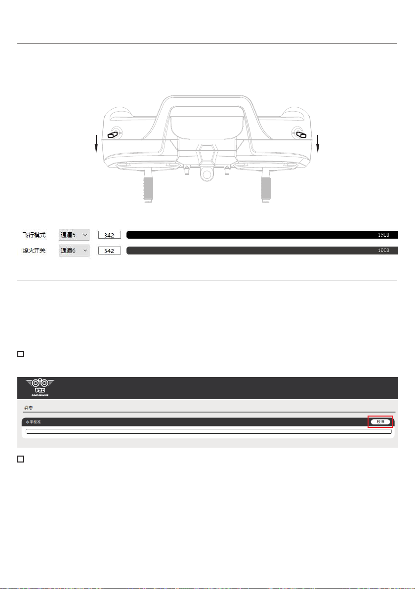
Move both selected 2-position switches to the forward position (as shown in figure 4). The values for channels
5 and 6 should be 1900 (as shown in figure 5).Click the "Reverse" checkbox on the right to reverse the
direction if the values are 1100 and click "Save" to finish the direction setting.
Figure 4
Figure 5
Flight Control Calibration
The flight control has been calibrated before leaving the factory, calibration is not necessary during the initial
installation. Ensure that the installation position is level and positioned as close to the center of gravity of the
aircraft as possible.
During calibration, remove the flight control from the aircraft and place it on a level and stable surface.
Failing to do so may result in significant deviations in flight attitude.
To connect the flight control to the computer using a USB data cable and multi-function control unit, without
turning on the transmitter or connecting the receiver. Open the FXZ software and click the "Altitude" button
in the bottom left corner of the calibration page to enter the "Flight Control Calibration" page.
Click the "Calibrate" button on the right side and wait for the calibration to complete. The "Calibrate" text will
appear in gray, and it will return to black once the calibration is finished.
13
Page 15
EN
Difference between Beginner Mode and Experienced Mode
In Experienced mode (3-axis mode), when the aircraft tilts to the left or right, the aileron control surface will not
automatically return to its neutral position.
In Beginner Mode (6-axis mode), when the aircraft tilts to the left or right, the aileron control surface will slowly
return to its neutral position on its own.
Control Direction Test
Power on the transmitter and turn on throttle cut, place the aircraft on level ground away from obstacles and
power on the aircraft to let it fully initialize. Move the sticks on the transmitter as below and observe the control
surfaces on the aircraft. Ensure the aircraft control surfaces respond as below and return to neutral when the
control input is released.
Aileron: Move the aileron stick to the left, the left aileron should move up. Move the aileron stick to the right,
the left aileron should move down.
Elevator: Pull the elevator stick backward, the leading edge of elevator should move up. Push the elevator
stick forward, the leading edge of elevator should move down.
Rudder: Move the rudder stick to the left, the rudder should move to the left. Move the rudder stick to the right,
the rudder should move to the right.
Flight Control Correction Test
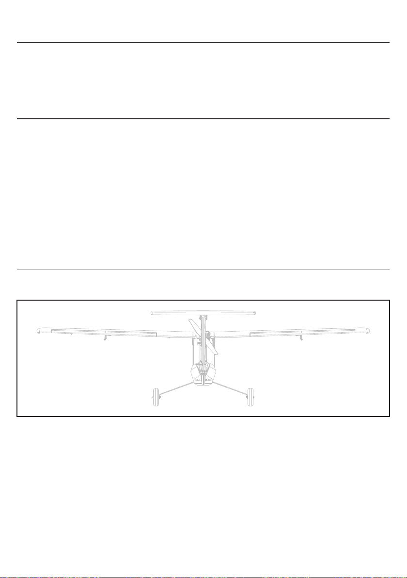
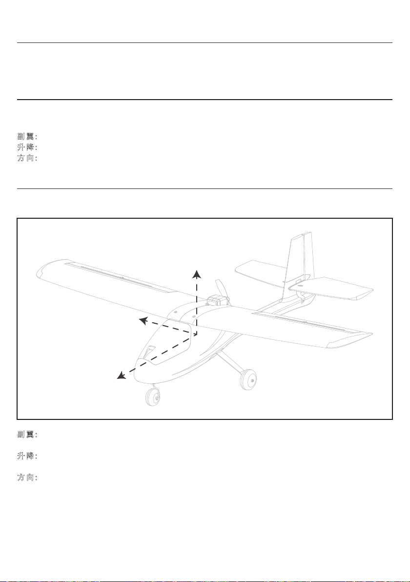
Point the nose of the aircraft away from yourself as shown in the diagram below.
Observe the control surfaces on the aircraft as below.
Aileron: Bank left the aircraft quickly, the left aileron should move down and the right aileron should move up.
Bank right the aircraft quickly, the right aileron should move down and the left aileron should move up.
Elevator: Make the nose of the aircraft go down quickly, the trailing edge of elevator should move up. Make
the nose of the aircraft go up quickly, the trailing edge of elevator should move down.
Rudder: Yaw the aircraft nose to the right quickly, the rudder should move to the left. Yaw the aircraft nose to
the left quickly, the rudder should move to the right.
14
Page 16
EN
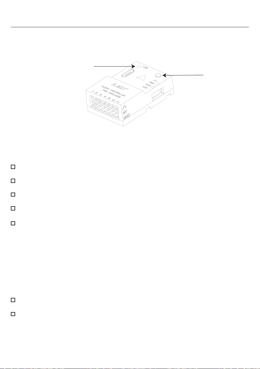
Parameter Setup Button
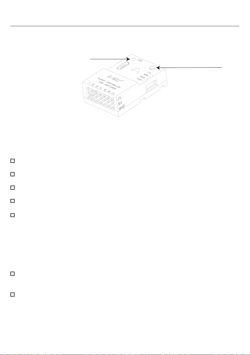
The flight control has a parameter setup button can be used to make precise adjustments to the neutral
position of each control surface. Before using the button, ensure to push all the trims on the transmitter to their
neutral positions.
LED Indicator
Parameter Setup Button
The parameter setup button is designed for short presses only. To enter the setup mode, power on both the
transmitter and the flight control. The LED indicator should glow solid blue to indicate normal operation.
Ensure that there is an appropriate interval between two button presses, without it being too short. When
entering the setup mode, the LED will blink red or purple if the servo is not in the neutral position. The LED will
glow solid purple if the servo is in the neutral position.
Press the button for the first time (the blue LED will blink once) to enter the neutral position adjustment mode
for the aileron servo. Adjustment can be made using the aileron stick.
Press the button for the second time (the blue LED will blink twice) to enter the neutral position adjustment
mode for the elevator servo. Adjustment can be made using the elevator stick.
Press the button for the third time (the blue LED will blink three times) to enter the neutral position
adjustment mode for the rudder servo. Adjustment can be made using the rudder stick.
Press the button for the fourth time (the blue LED will blink four times) to enter the neutral position
adjustment mode for the flap channel. Adjustment can be made using the rudder stick.
Press the button for the fifth time, and the LED will glow solid blue to indicate that the setup is completed.
(If no settings or actions are performed within one minute prior to this step, the system will automatically exit.
In such a case, the blue LED will revert to solid blue, and any adjusted parameters will not be saved.)
Each step mentioned above is adjusted by moving the corresponding stick on the transmitter up, down, left, or
right. If the red or purple LED blinks at an increasing frequency, it indicates that the control surface is moving
further away from the neutral point. if the blinking slows down, it means the control surface is approaching the
neutral point. When the LED turns solid purple, it indicates that the servo is in the neutral position.
Remarks:
To reset all servos, press and hold the "Parameter Setup Button" on the flight control for more than 6
seconds until the LED indicator turns from solid blue to blinking purple and returns to solid blue, then release
the button. All servos will automatically return to the neutral position.
To adjust the mechanical position of the servo arms or push-pull rods, press and hold the "Parameter Setup
Button" on the flight control for 3 seconds until the LED indicator light turns from solid blue to blinking purple,
then releasing the button and pressing it again, the LED indicator light will turn blinking red to indicate all
servos return to the neutral position and all the control surfaces have stopped moving, allowing you to make
the necessary adjustments. Press the button once again to finish the adjustments, the LED indicator light
will return to solid blue. This operation can be performed in both beginner flight mode (6-axis mode) and
experienced flight mode (3-axis mode).
15
Page 17
EN
External Parameter Setup Unit
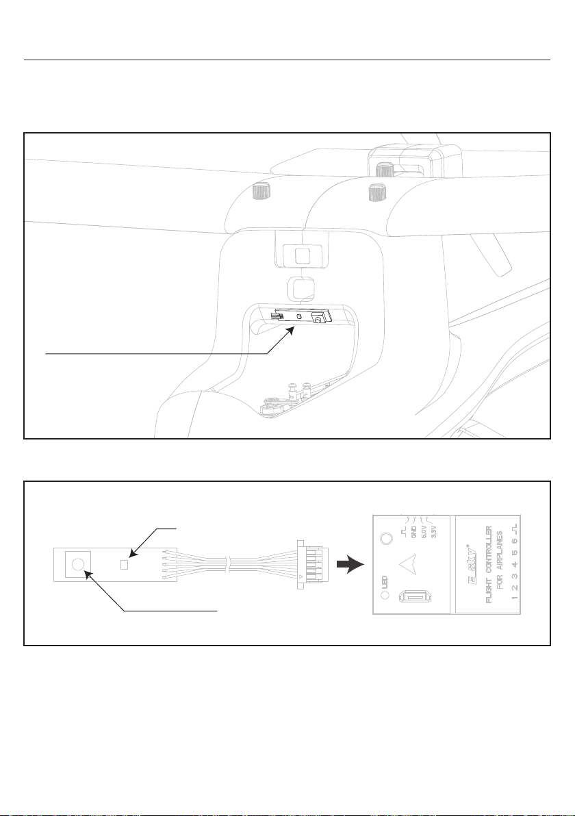
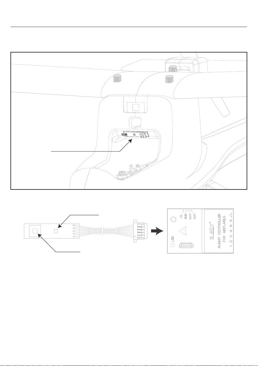
The external parameter setup unit is installed inside the aircraft, making it convenient to directly access and
adjust parameters. The usage method and steps are the same as the setup buttons on the flight control. The
diagram below shows the installation location for the external parameter setup unit.
External Parameter Setup Unit
The diagram below shows the connection between the external parameter setup unit and the flight control.
LED
Channel Pin Order
16
Page 18
EN
Control Direction / Mode Switch / Throttle Cut Switch Test
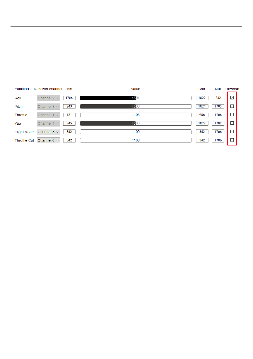
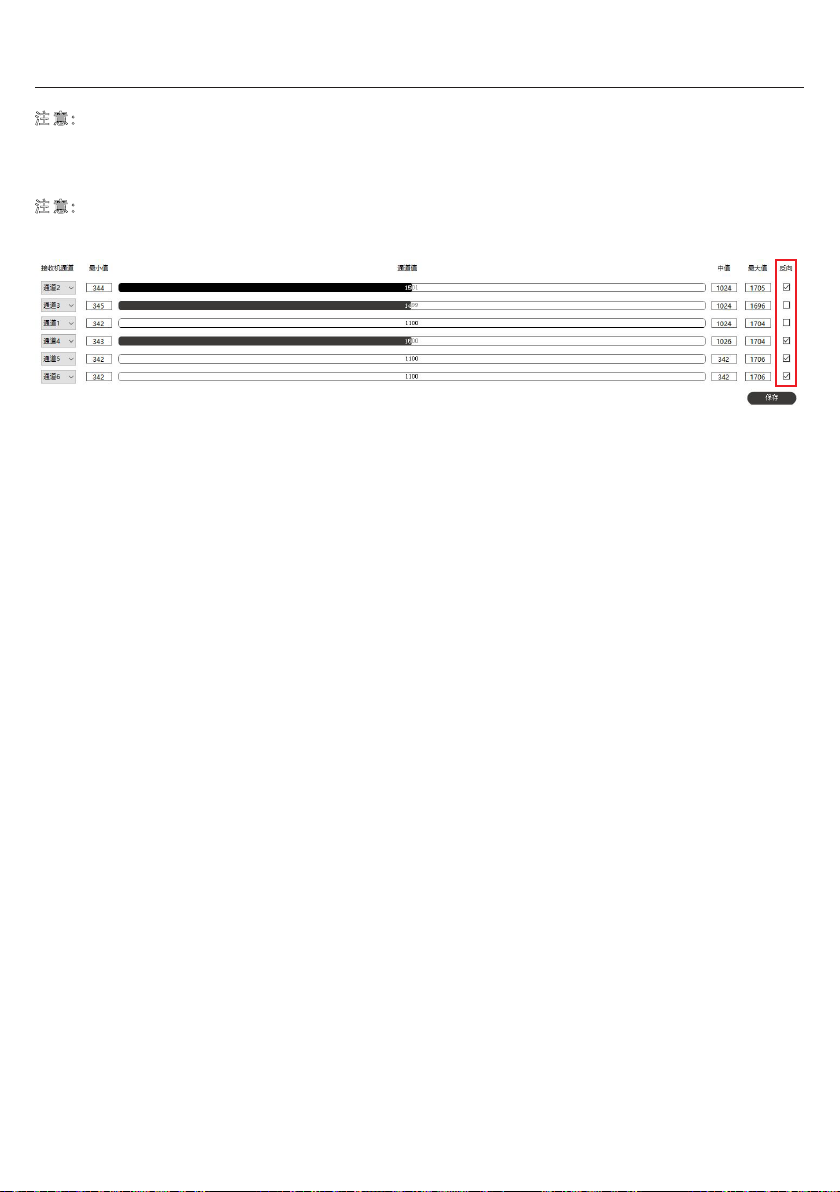
The receiver channels will automatically change based on the type of receiver being used. In case the
automatic recognition fails, you can manually select the appropriate receiver channel. When selecting
"Custom", choose the corresponding receiver channel for each function in the "Receiver Channel".
If the aircraft actions are reversed, you can adjust the corresponding channel's direction settings on your
transmitter. If your transmitter does not have this adjustment feature, you can switch on the "Reverse" option
located on the far right, as shown in the diagram below. Click the "Save" button to finish the settings.
17
Page 19

EN
Troubleshooting Guide
Situation: Unable to connect the parameter multi-function control unit to the computer
Reason/Solution: Please check the following
- Check if the USB cable is damaged or has any other issues
- Download the driver installation folder named "Driver1" for the computer from the official website and
proceed with the installation
- Download the driver installation folder named "Driver2" for the flight control from the official website and
proceed with the installation. If your computer is running a 32-bit system, select and install the
CP210xVCPInstaller_x86.exe file. If your computer is running a 64-bit system, select and install the
CP210xVCPInstaller_x64.exe file
Situation: After connecting the receiver to the flight control, there is no output from the flight control
Reason/Solution: Please check the following
- Check if the receiver and the transmitter have been properly bound
- Check the working status and output of the receiver to ensure they are functioning properly
- Check if the connection between the receiver and the flight control is correct
- Check if the receiver type is correctly selected in the configuration software
- Connect the flight control to the configuration software and perform a calibration of the input channels in the
configuration pageCP210xVCPInstaller_x64.exe file
Situation: Flight control outputs do not match the movements of the transmitter's sticks.
Reason/Solution: Please check the following
- Check if the output channel settings for the sticks and switches on the transmitter are correct
- After connecting the flight control to the FXZ software, check if the receiver channel settings are correct.
- After connecting the flight controller to the FXZ software, select "Custom" in the receiver channel page. Adjust
the receiver channel order as needed until the output channels match the transmitter
(Caution: Transmitter Calibration should be performed again after the adjustments)
Situation: Servo movements are reversed to the stick movements
- Find the output channel reverse setting on the transmitter and adjust the corresponding channel's setting
- If you are unable to adjust the output channel reverse on the transmitter , you can connect the flight control
to the FXZ software. Go to the flight control configuration page and check the "Reverse" checkbox next to the
corresponding channel, Press “Save” to finish the settings
18
Page 20
EN
Assemble the Aircraft
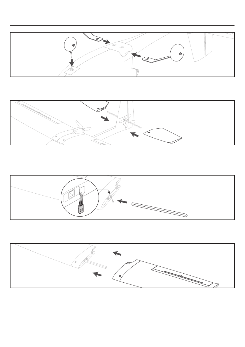
Slide the main gear into the slots in the fuselage until they lock into place and Insert the nose gear into the
wheel collar as shown and tighten the set screw against the flat in the gear wire using a screwdriver
Insert the tube through the hole in the vertical tail of the fuselage as shown, until the previously attached
horizontal stabilizer is against the fuselage. Slide the left and right horizontal stabilizer into the tube
(one side with “UP” inscribed on the horizontal tail should face up)
Slide the carbon fiber wing spar fully into a wing panel as shown
Ensure the aileron servo lead exits through the slot in the bottom of the wing
Slide the opposite wing panel over the wing spar until the root of the wing panels are tight and the rear
mounting hole is correctly aligned. Ensure both aileron servo leads exit through the bottom of the wing and are
not pinched between the wing panels
19
Page 21
EN
Assemble the Aircraft
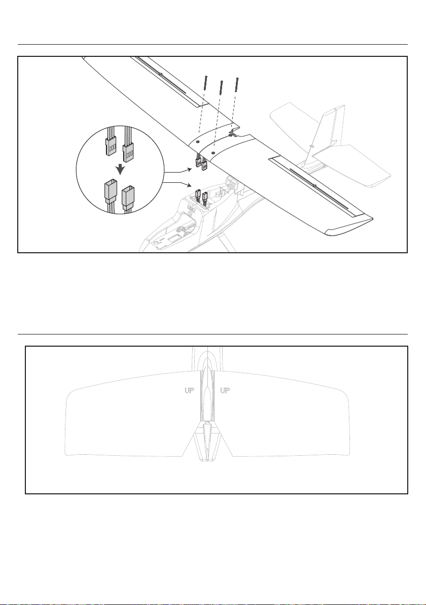
1. Connect the aileron servo leads to the y-harness installed in channel 1 of the receiver
2. Center the wing on the fuselage. Ensure the aileron leads are not pinched between the wing and fuselage
3. Attach the wing with the included 50mm screws. Do not overtighten the wing screws, as it may damage the
wing or the attachment points in the fuselage
Install the Horizontal Tail
As shown, the side marked “UP” of the horizontal tail should face up
20
Page 22
Install the Flight Battery
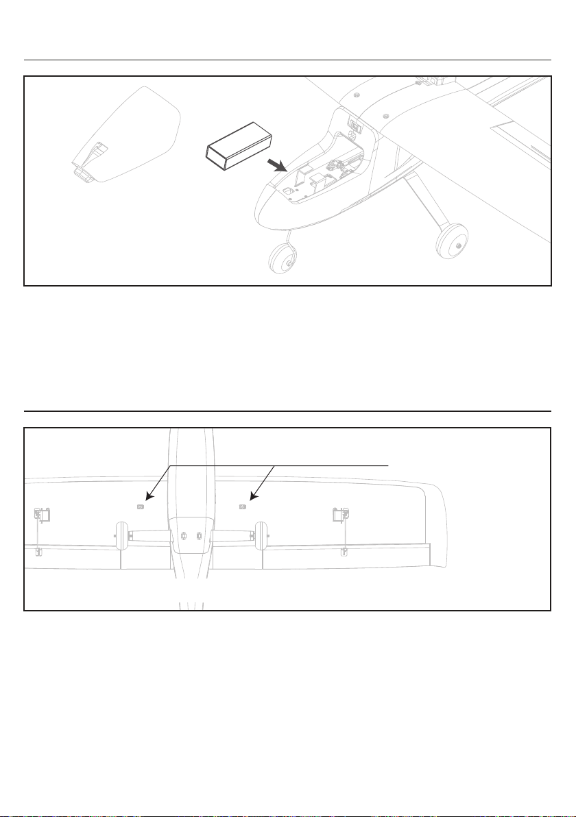
1. Lift at the rear of the battery hatch to remove it from the fuselage
2. Attach a piece of adhesive-back loop material to the bottom of the battery
3. Place the battery, loop material down, on the battery tray
The placement of the battery can be adjusted forward or backward to help balance the aircraft
4. When the battery is properly placed, secure it with the hook and loop strap
Center of Gravity (CG)
EN
CG (Center of Gravity)
As shown, the location marked “CG” at the bottom of the wing is the center of gravity position
An aircraft with the correct CG has its weight balanced on the center of the aircraft for safe and stable flight.
The aircraft CG and weight are based on having the recommended battery installed.
(11.1V 3S 2200mAh 20C Li-Po Battery, ~175g)
The CG location is marked on the bottom of the wing with a raised “CG”. Balance the aircraft on your fingertips
at the raised marks and adjust the battery position as needed get the aircraft to balance correctly.
- If the nose goes down, move the flight battery back until the aircraft balances.
- If the nose goes up, move the flight battery forward until the aircraft balances
21
Page 23
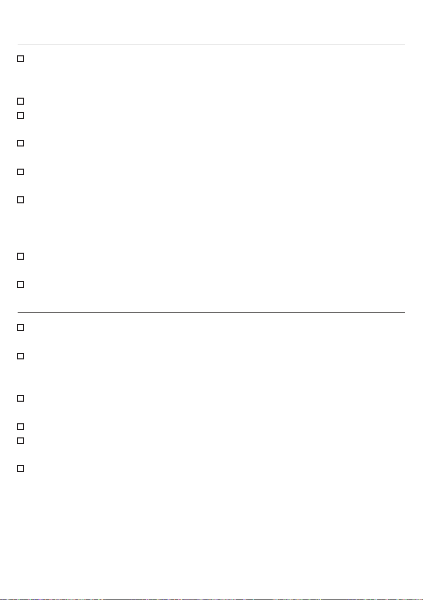
Pre-Flight Checklist
Stand behind the aircraft and always turn the transmitter on first
Ensure the transmitter controls are in the neutral position, the throttle is at its lowest position, and switch on
the THROTTLE CUT switch to ensure the motor cannot rotate
Plug the flight battery into the aircraft and position it on a level, unobstructed open field
Check the aileron movement
Move the aileron stick left, the left wing will tilt up and right wing will tilt down
Check the rudder movement
Move the rudder stick left, the rudder will turn left
Check the elevator movement
Push the elevator stick up, the front edge of left and right horiontal tail will tilt up
Check the alignment
Keep the throttle at zero and set the aileron, rudder, and elevator to neutral. Check the control surfaces of
the aileron and rudder to ensure they are centered and
by 1mm.
If the aircraft do not respond as described above, DO NOT FLY!
Refer to the “Troubleshooting Guide” for more information
If the aircraft responds as described above, proceed to the "Flying Checklist" section
If any of them are not in the right position, adjust the pushrod of the servo
the leading edge of elevator should move downward
Flying Checklist
EN
Always turn the transmitter on first
Set the THROTTLE CUT switch on the transmitter to the position marked by the red dot
Plug the flight battery into the aircraft, place it on a level surface and allow it to initialize
After plugging the flight battery, do not touch the aircraft and allow it to initialize. Secure the flight battery
with the hook and loop strap, replace the battery hatch after the aircraft has successfully initialized.
Place the aircraft in an unobstructed open field and takeoff with upwind (If there is wind)
Pilots stand on a safe, unobstructed and well-viewed area
Switch off the THROTTLE CUT switch on the transmitter to ensure normal power output
Push the throttle stick up and pull down the elevator stick, fly the aircraft
Once at the appropriate altitude, use the transmitter sticks to steer the aircraft along the desired path.
Land the aircraft
This aircraft has an assisted landing feature in the beginner mode (6-axis gyro). When the aircraft's altitude
is below 8 meters, lowering the throttle stick to the lowest position will trigger an automatic and smooth
landing. Adjust the landing altitude based on the runway conditions
Skill 1: Ensure the throttle stick maintain in the center when taking off, It help the aircraft keep steady during the take-off period
Skill 2: During the take-off period, push the throttle higher and pull the elevator lower will shorten the take-off time
Skill 3: Find an unobstructed open field to land the aircraft. Begin the landing by lower the throttle and decending towards the runway.
Once the aircraft about to touchdown, gently pull back the elevator to raise the nose and flair for a gentle landing
22
Page 24
EN
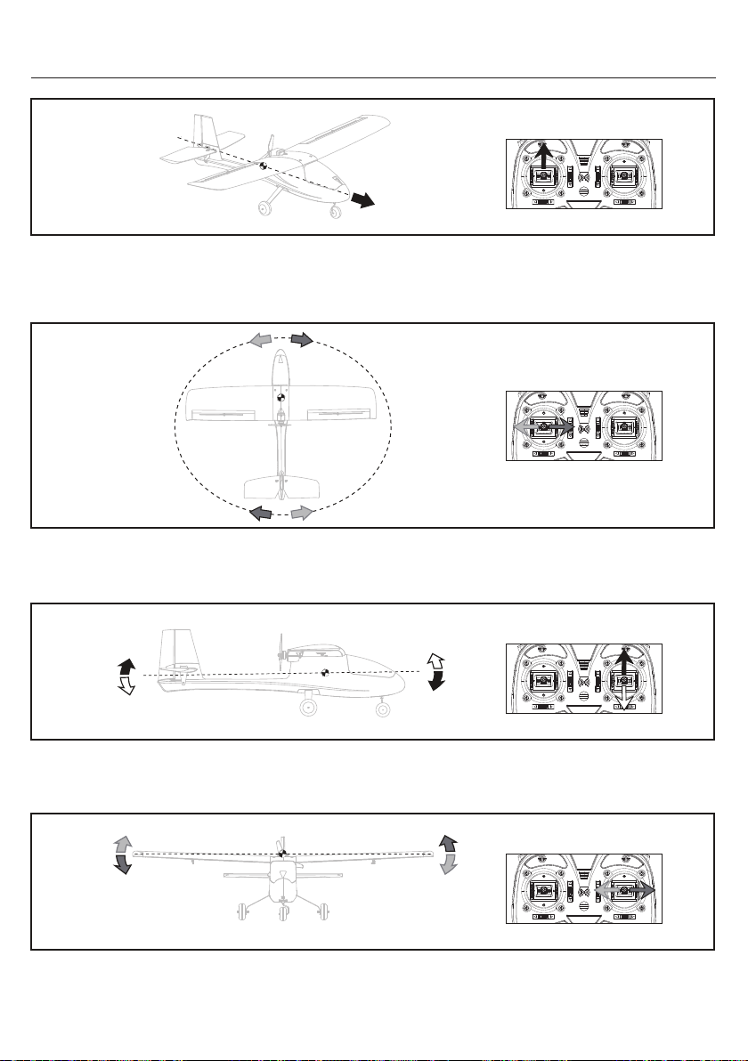
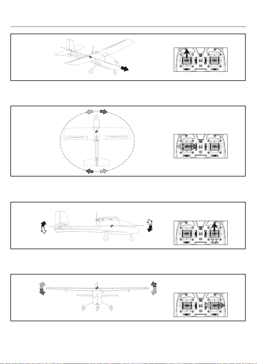
Transmitter Control Direction - Left hand throttle Mode 2
Mode 2
Push the “Left Stick” up, the aircraft motor speeds up to make the aircraft go faster.
When pulling the “Left Stick” down, the aircraft motor speeds down and slow down the aircraft.
This procedure is throttle control.
Mode 2
Move the “Left Stick” left or right to point the nose of the aircraft left or right.
The rudder stick is also used to steer the aircraft left and right while taxiing on the ground. This procedure is rudder control.
Mode 2
Push the “Right Stick” up to make the aircraft go down.
Pull the “Right Stick” down to make the aircraft go up. This procedure is elevator control.
Mode 2
Move the “Right Stick” left to make the aircraft roll or bank left.
Move the “Right Stick” right to make the aircraft roll or bank right. This procedure is aileron control.
23
Page 25
EN
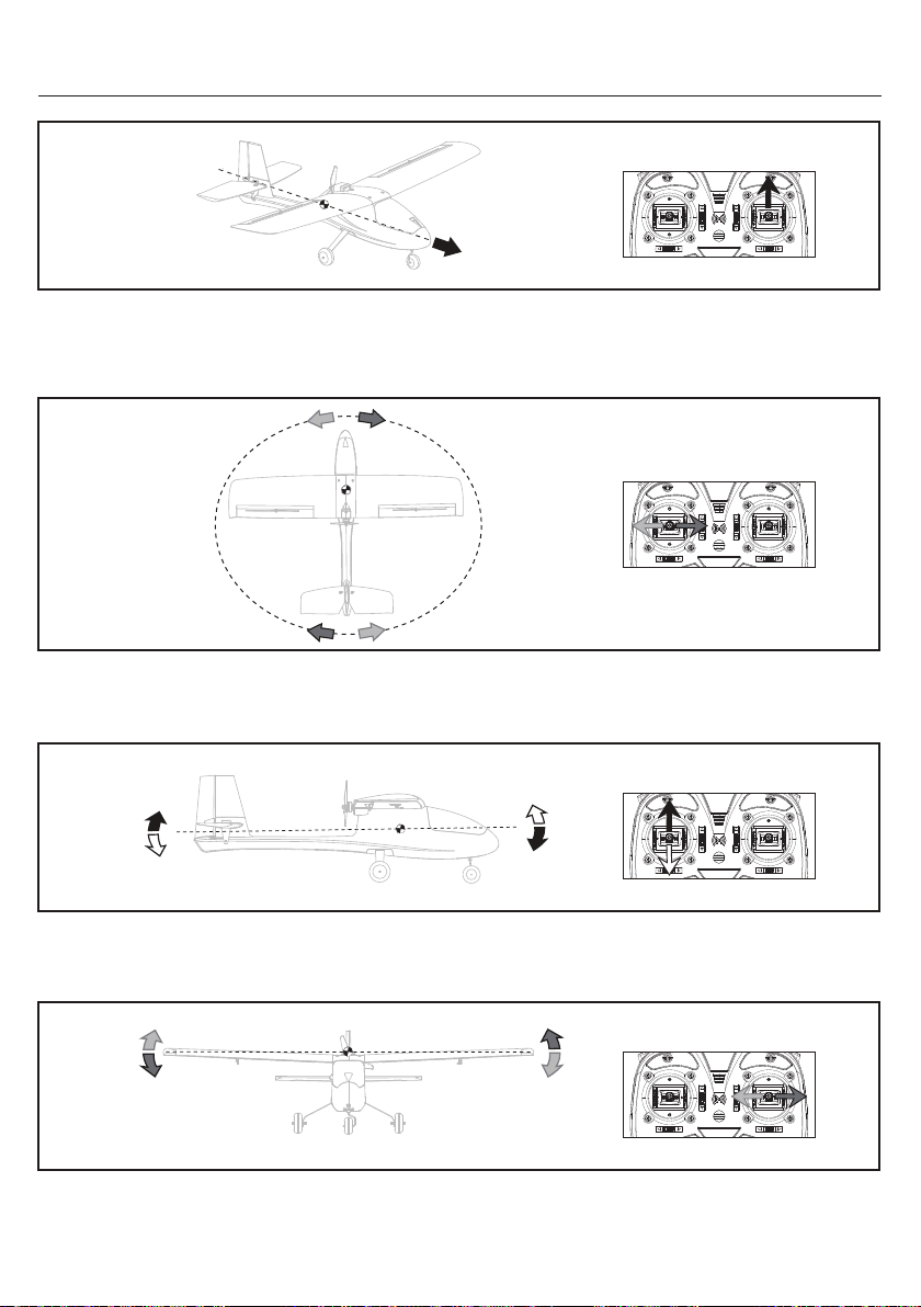
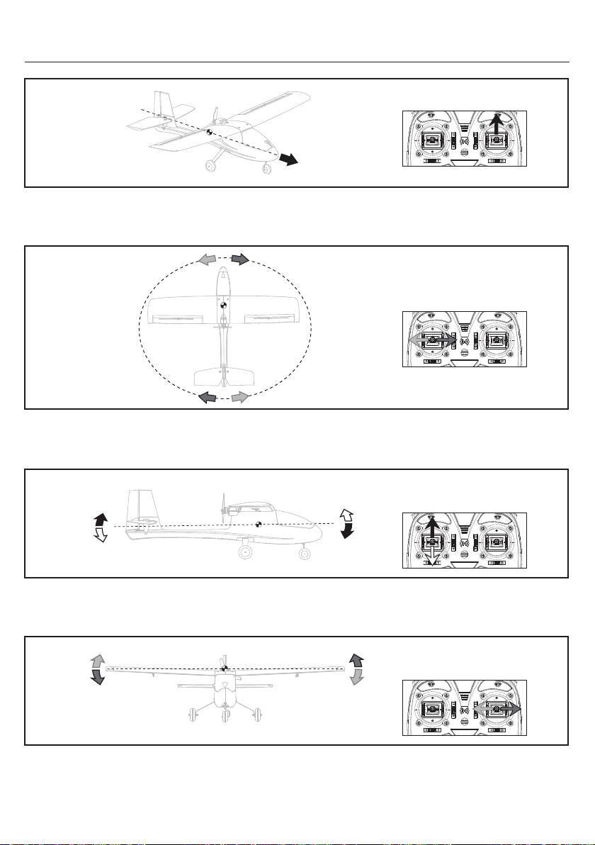
Transmitter Control Direction - Right hand throttle Mode 1
Mode 1
Push the “Right Stick” up, the aircraft motor speeds up to make the aircraft go faster.
When pulling the “Right Stick” down, the aircraft motor speeds down and slow down the aircraft.
This procedure is throttle control.
Mode 1
Move the “Left Stick” left or right to point the nose of the aircraft left or right.
The rudder stick is also used to steer the aircraft left and right while taxiing on the ground. This procedure is rudder control.
Mode 2
Push the “Left Stick” up to make the aircraft go down.
Pull the “Left Stick” down to make the aircraft go up. This procedure is elevator control.
Mode 2
Move the “Right Stick” left to make the aircraft roll or bank left,
Move the “Right Stick” right to make the aircraft roll or bank right. This procedure is aileron control.
24
Page 26
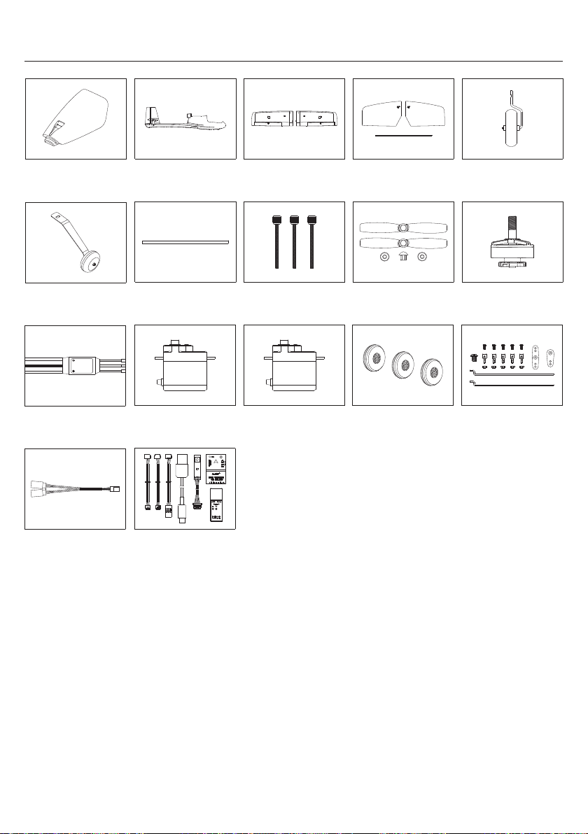
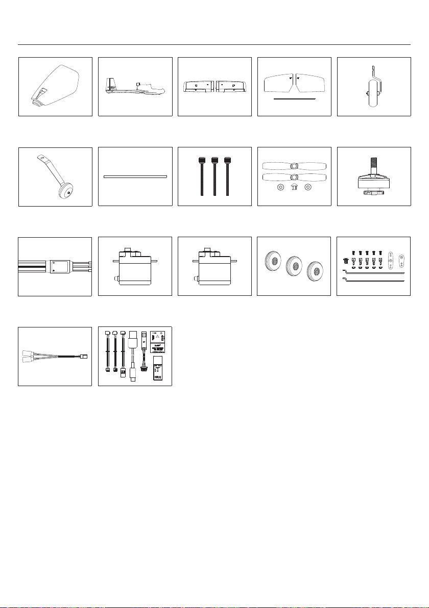
Parts Listing
EN
ESKY007789
Canopy Cover KIT Wing Set
ESKY007795 ESKY009152
Main Landing Gear Set
ESKY007804 ESKY007837
ESC 30A (PNP)
ESKY008147 ESKY008964
100mm Y-Harness Set
ESKY009297 ESKY007794
Fuselage Set
ESKY007796
Carbon Tube Set
ESKY007805
Servo with Lead 200mm
Flight Control Set
Wing Bolts Set
Servo with Lead 300mm
ESKY009299ESKY009298
Horizontal Tail Set
ESKY009151ESKY007797
Propeller Set
ESKY007836ESKY007806
Airplane Wheel
Nose Landing Gear Set
Brushless Motor
Accessory Bag
25
Page 27
产品参数 & 配置 & 包装内容 .........................................................................
飞机零件介绍 .........................................................................................
组装飞机前注意事项 ...............................................................................
飞控简介 ..................................................................................................
飞行模式 ...................................................................................................
飞控配置 ...........................................................................................
遥控器校准 .........................................................................................
飞控水平校准方法 ..................................................................................
自稳模式和增稳模式简单判断方法 .................................................................
舵面偏转与遥控器摇杆控制是否正确的判断方法 ..........................................
飞控按键功能简介和使用 ..............................................................................
外接调参板简介和使用 ..............................................................................
检查飞机动作、模式开关及熄火开关功能是否正确 ...........................................
异常及排除 ........................................................................................
组装飞机 .................................................................................................
平尾组装须知 ........................................................................................
飞行电池安装方法 & 重心调整方法 ....................................................................
起飞检查 & 飞行操作步骤 ........................................................................
发射机控制说明 ....................................................................................
配件表 .................................................................................................
CN
安全注意事项和警告
本产品是通过无线电信号控制的,在操作时可能会受到其他无线电信号干扰,此干扰可能会影
响本产品性能甚至会导致本产品失控。
1. 本产品具有一定的危险性,禁止14岁以下人士进行操作!
2. 不要将产品直接暴露在火或者对温度有影响的热源下。
警 告
禁 止
目录
3. 建议在5-35度,相对湿度20%-80%的环境中使用此产品。
4. 建议在没有风扇,冷气机,台灯或其他危险物件的地方操作此产品。
5. 电机为发热部件,请勿触摸,以免烫伤。
1. 飞行时要远离人群,避免旁人围观!以免误伤他人!
2. 本产品内部是由许多精密的电子零件组成,因此必须保证防潮防水,避免在浴
室或雨雾天气时使用,以免水气进入机体内部导致机器零件或电子零件故障而引
发不可预测的意外。
3. 请勿对本产品进行任何改装或拆解。
4. 本产品在飞行运转时禁止用手或其他物品触及本产品的任何部位!避免造成不
必要损失及人身伤害!
29-31
33-35
35-37
43-44
47-48
27
28
32
33
37
38
38
39
40
41
42
44
45
46
49
26
Page 28
最大飞行时间 ............................
主体材质 ....................................
电池接头 ...................................
飞控 ....................
充电器
发射机 / 接收机
产品参数
CN
翼展 ....................................
全长 .....................................
起飞重量 ...................................
配置
电机 .......................
电调 ..............................
舵机 .............................
电池 (不包含)
.....
无刷2306-2250Kv
30A BEC 3A
8克数字舵机
建议 3S 2200mAh 20C
包装内容
1 x 机身
1 x 左机翼
1 x 右机翼
1 x 左平尾
1 x 右平尾
3 x 接收机连接线
1 x 调参模块
1100mm
871mm
755g
(不包含) ............
1 x 机翼连接管
1 x 平尾连接管
1 x 前起落架
2 x 主起落架
3 x 机翼固定螺栓
1 x USB线
Esky 增稳/自稳陀螺仪
2S/3S平衡充电器
(不包含) ........
15分钟
EPO
XT60
六通及以上
27
Page 29
飞机零件介绍
CN
机翼连接管
机舱罩
机身
右机翼
飞控系统
垫圈
电机
前起落架
右平尾
平尾连接管
螺旋桨
螺母
左平尾
机翼固定螺栓
左机翼
主起落架
28
Page 30
CN
组装飞机前注意事项
注意:此款 Esky 雏鹰练习机不含发射机、接收机、充电器和动力电池,玩家需自备。
发射机需六通及以上,并带有两个及以上两段或三段开关;并先确认接收机供电电压及连接线序
后再将接收机接入飞控,避免因操作不当造成接收机或飞控损坏。在组装飞机之前需将选用的
接收机完成对频,并使用匹配的接收机连接线将接收机连接到飞控对应的插孔位上,然后进行
飞机的组装。
如果是复杂遥控器(有屏幕及设置功能的遥控器),需新建一个模式,模型选择飞机(固定翼模型
,正常尾翼)
Esky增稳/自稳飞控兼容接收机输入信号为:PPM、SBUS、DSM、DSM\SRXL2、IBUS、CRSF
飞控及其安装位如下图所示:
接收机端口
5V接收机端口(JR插头)
Rudder
Throttle
Elevator
Aileron
29
Page 31
组装飞机前注意事项
各种接收机与飞控的连接如下图所示:
橙色线
黑色线
红色线
方向
油门
升降
副翼
ZH4Y转ZH3Y插头
5V接收机连接线
GND
5V
CN
5V 接收机
副翼
升降
油门
方向
橙色线
黑色线
红色线
ZH4Y转JR插头
5V接收机连接线
30
5V
GND
5V 接收机
Page 32
组装飞机前注意事项
各种接收机与飞控的连接如下图所示:
白色线
黑色线
红色线
方向
油门
升降
副翼
ZH4Y转ZH3Y插头
3V接收机连接线
GND
3.3V 接收机
3.3V
CN
5V 接收机
5V双JR插头连接线
(不包含)
31
SS
5V
GND
Page 33
重量 ............................................
输入电压 ..................................
输出PWM数量 ..............................
飞控简介
1 -副翼
2 -升降
3 -油门
4 -方向
5 -辅助1
6 -辅助2
-5V接收机端口(JR插头)
产品参数
调参端口
CN
LED指示灯
调参按键
接收机端口
各通道排针顺序
长度 .......................................
宽度 .......................................
高度 ..........................................
附带调参配件
36.2mm
24.4mm
12mm
外接调参板(已装机)
USB线
调参模块
32
7.8g
5V±0.5
6通道
Page 34
飞行模式
此飞行控制模块有两种飞行模式,自稳模式(6轴模式)和增稳模式(3轴模式)。
CN
自稳模式:
机不能实现横滚、倒飞、拉筋斗、垂直爬升或俯冲等特技动作。除了在操控瞬间飞机能够有限
改变姿态外,其它时候飞机将一直保持当前的水平直线飞行状态。此模式适合新手练习。
增稳模式:
置偏差或飞机设计引起的飞行不稳定性问题,纠正和稳定飞机瞬时飞行姿态,使飞行更加平稳
,同时不会干扰飞行员的操纵意图;飞机可以实现横滚、倒飞、拉筋斗、垂直爬升或俯冲等特技
动作。此模式适合高手及进阶练习。
特别说明:
器的 6 通道为熄火开关控制通道,2档或3档开关均可,此默认设置不可更改。其中,飞控通道
插槽上的“辅助 1”和“辅助 2”通道,在遥控器通道数和功能允许的情况下,可根据需要进行
分配使用,比如用于收放襟翼或是收放起落架等(仅可设置 1~6 通道以外的通道数)。
此模式下系统能确保飞机保持水平直线飞行,飞机能够进行基本的飞行操作。但是飞
在这种模式下,系统可以辅助对抗和修正由外部力量如风、湍流、机翼失速、重心位
飞控系统默认状态下,模式切换控制为遥控器的 5 通道,2 档或 3 档开关均可;遥控
飞控配置
备注:在进行如下操作之前请先打开发射机。
通过以下二维码下载 FXZ 上位机。
https://www.esky-rc.com.cn/manual/detail/9
双击【FXZ 程序】打开飞控配置软件。
将连接飞控端的调参工具模块上的拨动开关调至USB端。如下图
将飞控、调参工具与电脑连接(如下图),配置软件将自动识别并连接飞控,如未自动连接请
选择正确串口后点击连接。
Micro USB接头
电脑
33
Page 35

EN
飞控配置
待配置软件界面左下角显示【飞行控制】和【姿态】后
点击【飞行控制】进入【飞行控制系统】界面。
如下图1所示根据所使用的接收机类型选择正确的接收机协议。选择完接收机协议后,系统会
根据所选接收机协议自动匹配通道顺序且前四个通道是灰色字体不能修改,如下图2;如果想
改动默认通道顺序,可选择【接收机通道】栏右边的【自定义】,如图3;此时所有的通道可
根据需要自行匹配;然后点击【保存】。设置完成此步后,需点击【保存】按钮进行保存,待
短暂显示【保存成功】并恢复到【保存】字样后,再进行下一步设置。
圖1 圖2
圖3
34
Page 36
CN
遥控器校准
遥控器校准操作如下:
在进行遥控器校准之前,请将各通道微调调整至中立位置。下面的操作是以左手油门为例:
行程校准:点击右上角【开始校准】按钮:左、右手分别按住或捏住左、右摇杆,两摇杆左边和
右边均运行到左右两端极限位置(如图1所示);两摇杆上边和下边均运行到上下两端极限位置,
然后松开手并让油门摇杆立于中间位置(如图2所示)。5、6通道对应的2段开关拨向前后两端
最大最小位置(如图3所示),然后点击【完成校准】。
等待系统更新结束,遥控器校准完成。
图 1
图 2 图 3
35
Page 37
CN
遥控器校准
检查通道正反向:左、右摇杆一起拨至摇杆总成座右上角极限位置,如图4所示。
图 4
此时 1、2、3、4 通道需要显示1900或是接近1900的数值。如果有显示 1100 或是接近 1100
的数值,请点击勾选此栏对应最右侧的反向方框中进行方向调整切换,并点击【保存】。如下
图
如果左、右摇杆一起靠在左下角,则 1、2、3、4 通道需要显示1100或是接近 1100 的数值。
如下图:
36
Page 38
CN
遥控器校准
如图5所示,关于 5、6 通道,请把2个选定的2段开关全部拨向前端,此时5、6通道数据需要显
示1900,如果有显示1100的,请点击勾选此栏对应最右侧的【反向】方框中进行方向调整切换
,并点击【保存】。
图 5
图 5
飞控水平校准方法
此飞控出厂前已经做了水平校准。购买ESKY飞机带此飞控,则无需校准;如果飞机出现炸机或是
多次大强度的撞击后出现了飞行姿态的明显偏差而且与飞机结构和气动损伤没有关系的,可以
考虑重新校准飞控。校准时需将飞控取下放置在水平的平面操作台上并固定牢靠,再进行校准
。校准过程中飞控不能被移动。如果飞机上安装飞控的位置不平整或是有损伤,也有可能导致
飞行姿态的较大偏差。
使用USB数据线和调参模块连接飞控和电脑,无需打开发射机,也可不连接接收机。打开
FXZ 调参界面,点击界面左下角【姿态】模块,进入飞控水平校准界面。如下图所示:
点击右侧的【校准】等待校准完成
(此过程中【校准】字体为灰色,校准完成后重新变回黑色)。
37
Page 39
自稳模式和增稳模式简单判断方法
自稳模式下,当飞机左右倾斜时,副翼舵面翘起来后不会自己回正。
增稳模式下,当飞机左右倾斜时,副翼舵面翘起来后会自己缓慢回正。
判断舵面偏转是否正确
飞机平放,将机头朝前,人站在飞机的后面,确保打开熄火开关,无动力输出。
副翼:
往左偏转副翼摇杆,左边副翼往上偏转,右边副翼往下偏转;
升降:
往下拉杆,升降舵往上偏转(如果是全动平尾,则整个平尾往上偏转)
方向:
往左偏转方向舵摇杆,方向舵往左边偏转。
判断飞控系统对舵面修正方向是否正确(两种飞行模式通用)
将机头朝前,人站在飞机的后面,飞机平放在手上。
Z轴
CN
Y轴
X轴
副翼:
绕着机身轴线(上图中的X轴)快速的往左偏转飞机。
左边副翼需往下偏转,右边副翼需往上偏转。
升降:
绕着上图中的 Y 轴快速的将机头朝下,升降舵往上偏转。
(如果是全动平尾,则整个平尾往上偏转),如果是机尾朝下,则修正方向相反。
绕着上图中的 Z 轴快速往左摆动机身尾部,则方向舵往左边偏转,反之亦然。
方向:
38
Page 40
CN
飞控按键功能简介和使用
此飞控有一个调参按键,用于对各舵面中立位较为精确的调整,
有需要的可以使用此功能。使用按键调参之前,请将遥控器各通道微 调调整至中立位置。
LED指示灯
调参按键
调参按键只有短按方式,打开发射机,给飞控通电,正常状况下LED指示灯蓝色常亮。两次按键
的间隔时间不能过短,需等每一步的流程走完后在进行下一步按键操作,并且每进入一个调参
状态时,LED指示灯的颜色可能是红色闪烁(表示舵机不在中立位),紫色闪烁(表示舵机不在中
立位)或是紫色长亮(舵机处于中立位置):
短按第一次按键并松开: 蓝灯闪烁一次,然后进入副翼舵机中立位调整状态
(配合副翼摇杆增减操作);
短按第二次按键并松开: 蓝灯闪烁二次,然后进入升降舵机中立位调整状态
(配合升降舵摇杆增减操作);
短按第三次按键并松开: 蓝灯闪烁三次,然后进入方向舵机中立位调整状态
(配合方向舵摇杆增减操作);
短按第四次按键并松开: 蓝灯闪烁四次,然后进入襟翼通道中立位调整状态
(配合方向舵摇杆增减操作);
短按第五次按键并松开: LED指示灯变为蓝色常亮,保存参数调整结束。
(此步骤之前任一步操作,如果一分钟内不进行任何设置和动作,系统将自动退出,蓝灯常亮
并且已调整的参数不会保存)
调参过程是滚动式操作,一步都不能少,需等待以上五个步骤进行完后所修改的参数才会得以
保存。由于此固定翼飞机(不带襟翼和收放起落架),襟翼通道中立位无需进行调整。
以上每步操作均通过遥控器上对应通道摇杆上下或左右摇动进行调整;如果红灯或是紫色灯闪烁
的频率越来越快,说明舵面离中立点越来越远,反之则越来越近,直至灯的颜色变为紫色常亮
,表示此时舵机处于中立位置。
备注:
以上步骤如果操作过程中出现差错混淆或是其它因素需要所有舵机重新复位的。
可以长按“调参按键”6秒以上松开,灯的颜色变化:蓝灯常亮-紫色闪烁-蓝灯常亮。
如果需要对舵机摇臂或是推拉杆机械位置进行调整,可以长按“调参按键”3秒,待指示灯变
为紫色闪烁后松开再按一次,指示灯的颜色变为红色闪烁,此时所有舵机回到中立位,舵面
停止动作。待调整完成后再短按一下按键,指示灯恢复蓝灯常亮,所有舵面恢复正常工作状
态。此操作在增稳模式和自稳模式下均可进行。
39
Page 41
CN
外接调参板简介和使用
外接调参板安装于飞机机舱内部,方便直接操作调参,使用方法和步骤与飞控上的调参按键相
同。如下图所示:
外接调参板
调参板功能按键及指示灯、与飞控模块连接示意图如下:
LED指示灯
调参按键
40
Page 42
CN
检查飞机动作、模式开关及熄火开关功能是否正确
注意: 接收机通道会根据接收类型自动更改,如自动识别失败可手动选择正确的接收机通道,当
选择自定义时请在【接收机通道】栏内手动选择各功能对应的接收机通道,修改完成后点击保
存。
注意:
飞控输出动作反向时可在遥控器内调整对应通道的正反向设置,如遥控器不具有调整功能
,可在下图所示最右侧的 【反向】栏进行切换,完成后点击【保存】按钮。
41
Page 43
CN
异常及排除(如果以下方法未能解决问题,请与售后支持联系)
情况:USB 线与电脑不能正常连接
解决方法:
-检查 USB 线是否有破损或是其它问题。
-在官网上下载driver1电脑驱动安装文件夹进行安装。
-在官网上下载driver2飞控驱动安装文件夹进行安装。
如果电脑是32位系统,选择安装CP210xVCPInstaller_x86.exe 。
如果是64位系统,选择安装CP210xVCPInstaller_x64.exe 。
情况:接收机与飞控连接后飞控无输出
解决方法:
-检查接收机与遥控器是否已经对频完成。
-检查接收机工作状态和输出是否正常。
-检查接收机与飞控连线是否正确无误。
-将飞控与配置软件连接检查配置界面接收机机类型是否选择正确。
-将飞控与配置软件连接,在配置界面重新进行输入通道校准操作。
情况:飞控与配置软件无法连接
解决方法:
-检查调参工具与飞控及电脑之间是否已正常连接。
-配置软件端口选择位置是否选择了正确的串口。
-调参工具上的切换开关是否选择在 USB 位置。
-关闭并重新打开配置软件选择正确串口后再将调参工具与飞控连接。
情况:飞控输出通道与遥控器摇杆不匹配
解决方法:
-检查遥控器内摇杆及开关与输出通道之间的设置是否正确
-将飞控与配置软件连接后检查接收机通道的设置是否正确
-将飞控与配置软件连接后在接收机通道设置内选择自定义后可根据需要调整接收机通道顺序直
至输出通道与遥控器匹配。(调整后需再次进行校准操作)
情况:拨动遥控器摇杆舵机输出动作与摇杆动作相反
解决方法:
-在遥控器内找到输出通道正反向设置,调整对应通道的正反向设置。
-如遥控器无法调整输出通道正反向可将飞控与配置软件连接,在飞控配置软件内勾选对应通道
后面的反向勾选框并保存。
42
Page 44
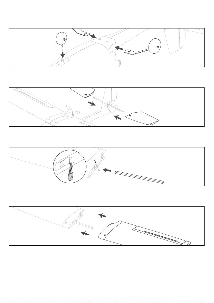
组装飞机
将主起落架插入机身上的插槽,向里滑动直至其卡扣锁定。
将前起落架上平台朝向安装座螺丝孔插入,用螺丝刀把螺丝拧紧。
将平尾连接管插入机身安装孔,再将左右平尾翼插入。注意平尾翼上"UP"字样朝上。
CN
将机翼连接管完全滑入右机翼。确保副翼舵机导线从右机翼底部的槽中引出。
将左机翼插到机翼连接管上, 直至左右机翼面板贴紧, 并且安装后左右机翼正确对齐。确保两条
副翼舵机导线均从机翼底部引出, 不能夹在左右机翼之间。
43
Page 45
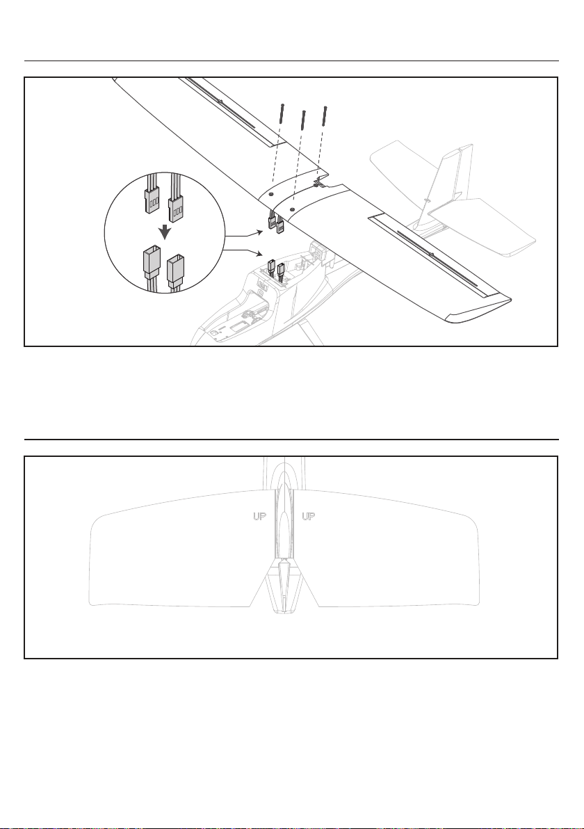
CN
组装飞机
将副翼舵机导线连接至安装在通道1的Y线束中。
将机翼在机身上居中。确保机翼和机身连接处未夹住任何电线。
用随附的50mm螺丝固定机翼。请勿过度拧紧螺丝,否则可能会损坏机翼或机身上的连接点。
平尾组装须知
如图中所示, 平尾上刻有"UP" 字样的一面需朝上
44
Page 46
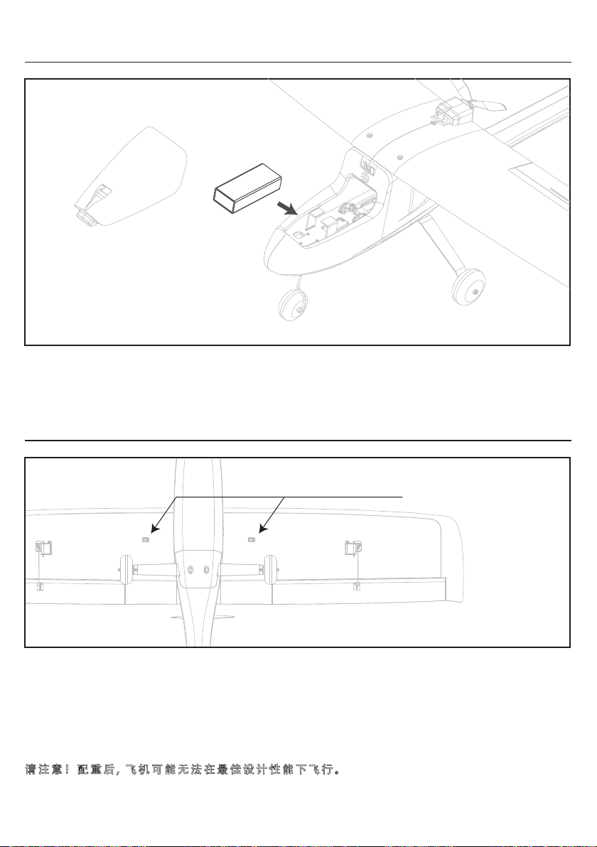
飞行电池安装方法
提起电池舱盖,以将其从机身上卸下。
将电池放在电池托盘上,电池位置可以向前或向后调节,以帮助平衡飞机。
正确放置电池后,用魔术带固定。
重心调整方法
CN
CG(重心位置)
如图中所示, 机翼底部标有"CG" 字样的部位为飞行重心位置
飞机安装完好后(含电池), 用双手的食指顶住飞机副翼底部2个CG小凸台, 若此时飞机姿态能
够水平或接近水平, 则重心正确。若此时飞机低头或抬头, 请后移或前移电池的安装位置。若
始终无法平衡重心, 则电池的重量太轻(飞机始终偏向抬头)或者太重(飞机始终偏向低头), 请
更换重量合适电池或自己进行配重。
请注意!配重后, 飞机可能无法在最佳设计性能下飞行。
45
Page 47
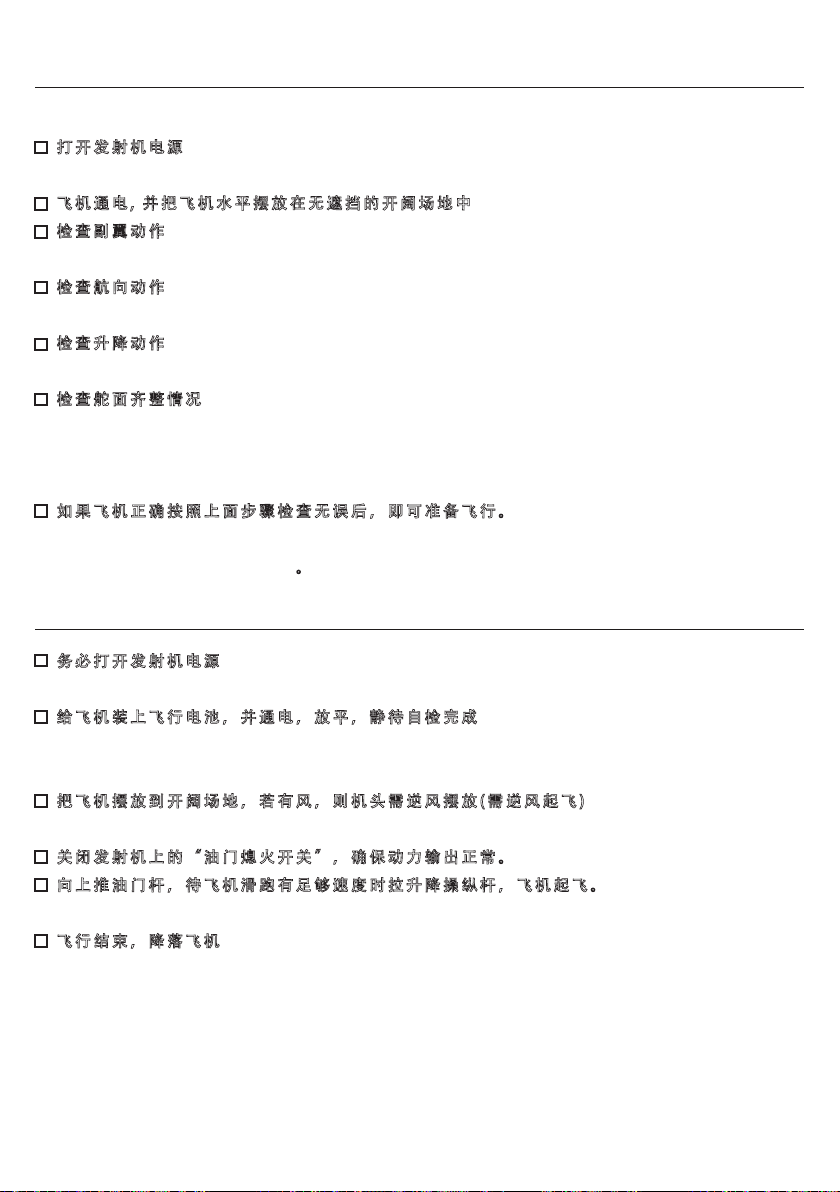
CN
起飞检查
站在飞机后面
打开发射机电源
注意把油门杆放在最低位置。打开油门熄火开关确保电机不能转动。
飞机通电, 并把飞机水平摆放在无遮挡的开阔场地中
检查副翼动作
副翼杆左打, 飞机副翼左侧后边沿上升, 右侧后边沿下降即为正确。
检查航向动作
航向杆向左打, 方向舵向左偏转即为正确。
检查升降动作
升降杆向上推, 尾水平翼前沿(朝机头方向)上升, 即为正确。
检查舵面齐整情况
将油门杆拉到最低, 方向杆, 副翼杆, 俯仰杆居中情况下, 副翼两端要对齐所在机翼 基准面, 方
向舵要居于垂尾的中线上,左右平尾要对齐端面形状且前端可以往下偏转 1mm左右。若出现
较大偏差, 可通过相应舵机拉杆锁紧螺丝进行调整。
如果飞机正确按照上面步骤检查无误后,即可准备飞行。
如果在检查中发现问题, 请务必不要飞行, 直至问题排除并解决;若有必要, 可联系忠
达模型售后服务中心进行咨询。
飞行操作步骤
务必打开发射机电源
打开发射机上的“ 油门熄火开关“ ,确保动力不能输出。。
给飞机装上飞行电池,并通电,放平,静待自检完成
飞机通电之后,马上放在水平面上不要动飞机,静待飞机自检完成。
飞机自检完成后,绑好电池并盖上电池仓盖。
把飞机摆放到开阔场地,若有风,则机头需逆风摆放(需逆风起飞)
飞行员找一个安全无遮挡且视线良好的场地站好。
关闭发射机上的“油门熄火开关”,确保动力输出正常。
向上推油门杆,待飞机滑跑有足够速度时拉升降操纵杆,飞机起飞。
起飞到合适高度,开始控制两个摇杆让飞机按照自己希望的轨迹飞行。
飞行结束,降落飞机
此飞控在自稳模式下有辅助降落功能,当飞机高度低于8米时,将油门杆拉到最低,飞机会自
动平稳降落。 降落前的高度请根据降落跑道条件进行调整。
小技巧1:起飞时推油门杆务必不要左右晃动,确保飞机加速阶段不会左右跑偏。
小技巧2:起飞阶段,推油门越高,向下拉俯仰杆越大的话,起飞距离越短,飞机越快离地。
小技巧3:降落时请找开阔场地, 修正飞机姿态, 收油门, 同时根据飞机降落情况向下拉俯仰杆, 尽量让飞机的
后轮先着地, 前轮最后着地。
46
Page 48
左手油门发射机控制说明 - Mode2
Mode 2
当"左摇杆"向上推动时, 飞机马达转速加快并使飞机向前加速飞行。
当"左摇杆"向下拉动时, 飞机马达转速降低并使飞机向前减速飞行。此过程是油门控制。
Mode 2
当"左摇杆"向左推动时, 飞机向左拐弯。
当"左摇杆"向右推动时, 飞机向右拐弯。此过程是航向控制。
CN
Mode 2
当"右摇杆"向上推动时, 飞机低头向下飞行。
当"右摇杆"向下拉动时, 飞机抬头向上飞行。此过程是俯仰控制。
Mode 2
当"右摇杆"向左推动时, 飞机向左侧倾斜飞行并有左拐弯现象。
当"右摇杆"向右推动时, 飞机向右侧倾斜飞行并有右拐弯现象。此过程是侧滚控制。
47
Page 49
右手油门发射机控制说明 - Mode1
Mode 1
当"右摇杆"向上推动时, 飞机马达转速加快并使飞机向前加速飞行。
当"右摇杆"向下拉动时, 飞机马达转速降低并使飞机向前减速飞行。此过程是油门控制。
Mode 1
当"左摇杆"向左推动时, 飞机向左拐弯。
当"左摇杆"向右推动时, 飞机向右拐弯。此过程是航向控制。
CN
Mode 2
当"左摇杆"向上推动时, 飞机低头向下飞行。
当"左摇杆"向下拉动时, 飞机抬头向上飞行。此过程是俯仰控制。
Mode 2
当"右摇杆"向左推动时, 飞机向左侧倾斜飞行并有左拐弯现象。
当"右摇杆"向右推动时, 飞机向右侧倾斜飞行并有右拐弯现象。此过程是侧滚控制。
48
Page 50
配件表
CN
ESKY007789
座舱罩 KIT机翼
ESKY007795 ESKY009152
主起落架
ESKY007804 ESKY007837
30A电调(PNP用)
ESKY008147 ESKY008964
100mm线長
Y型连接线
ESKY009297 ESKY007794
机身
ESKY007796
连接碳管
ESKY007805
200mm线長舵机
飞控模块
机翼固定螺栓
360mm线長舵机 机轮
ESKY009299ESKY009298
平尾
ESKY009151ESKY007797
两叶螺旋桨
ESKY007836ESKY007806
前起落架
无刷电机
附件包
49
Page 51
Page 52
Created 07/24
All instructions are subject to change at the sole discretion of Zonda Hobby. For up-to-date product literature, Visit
esky-rc.com and click on the support tab for this product.
忠达模型保留更改所有说明的权利,说明及其它附属资料的变更将不另行通知,如需更新或获
取更多资讯,请访问esky-rc.com.cn
 Loading...