

Page 1
150 Series
User Manual / 用户手册
/ 系列
Page 2

English .............................................................................................................................................................
中文 ..................................................................................................................................................................
Languages 语言
1-14
15-28
Page 3

Specifications & Helicopter Parts ..........................................................................................................
Box Contents .......................................................................................................................................
Battery Charging ..................................................................................................................................
Flying Checklist ..................................................................................................................................
Install and Remove the Flight Battery ......................................................................................................
Transmitter Control (RTF Version) - Left hand throttle Mode 2 .............................................................
Transmitter Control (RTF Version) - Right hand throttle Mode 1 .........................................................
Mode Switch and Altitude Hold with Barometer ....................................................................................
Throttle Cut ............................................................................................................................................
Transmitter and Receiver Binding ..........................................................................................................
Transmitter Low Voltage Warning ........................................................................................................
Maintenance Tool ...................................................................................................................................
Common Parts Listing ..............................................................................................................................
Dedicated Parts Listing ............................................................................................................................
Troubleshooting Guide ...........................................................................................................................
Safety Precautions and Warnings
This RC aircraft is controlled by radio signals. Other radio signals can potentially interfere with it’s operation.
This interference can cause the helicopter to lose control.
1. Improper operation of ESKY 150 V3 series may lead to damage or loss. lt is prohibited for
children under 14 years to operate this product.
2. Keep it away from high temperature environment for storage and flight.
3. Suggested operation temperature: 5-35°C , Humidity: 20-80%.
4. Keep away from fans, air conditioners and table lights while flying.
5. Do not touch the motor in case of damage or crash.
1. Keep away from crowds to prevent accidents.
2. Do not operate ESKY 150 V3 series in the shower room or in rain. Moisture can get inside the
aircraft which may cause electronic parts to malfunction.
3. Do not re-equip, upgrade or repair your helicopter with unauthorized parts.
4. Keep people and objects away from the spinning unit and parts to prevent damage or injury.
EN
Table of Contents
2
3
4
4
5
7
8
9
10
11
11
11
11
12
14
1
Page 4
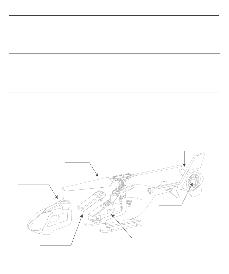
Specifications (ESKY150EC)
EN
Length ..............................................................
Height ................................................................
Main Rotor Diameter ........................................
Specifications (ESKY150V3)
Length ..............................................................
Height ................................................................
Main Rotor Diameter ........................................
Specifications (ESKY150BL)
Length ..............................................................
Height ................................................................
Main Rotor Diameter ........................................
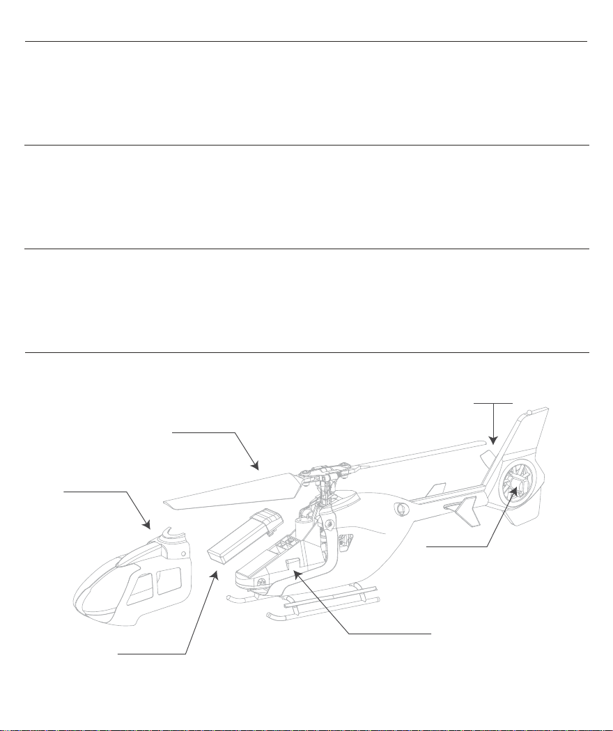
Helicopter Parts
Main Blade
179mm
68mm
168mm
179mm
62mm
168mm
186mm
59mm
168mm
Tail Rotor Diameter ...............................................
Flying Weight ...........................................................
Approx. Flight Time .........................................
Tail Rotor Diameter ...............................................
Flying Weight ...........................................................
Approx. Flight Time .........................................
Tail Rotor Diameter ...............................................
Flying Weight ...........................................................
Approx. Flight Time .........................................
5 Minutes
6 Minutes
6 Minutes
Tail Blade
38mm
37g
44mm
36g
42mm
36g
Canopy Cover
Flight Battery
Tail Motor
Multi Control Unit
2
Page 5
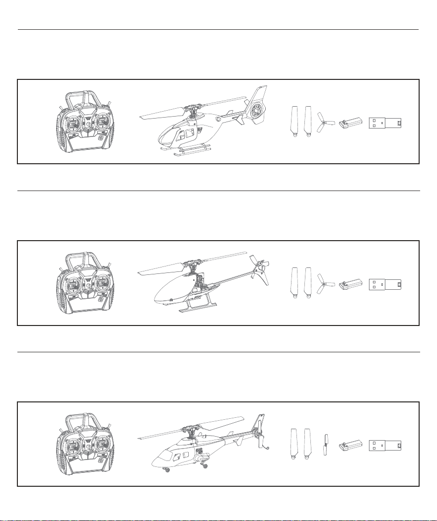
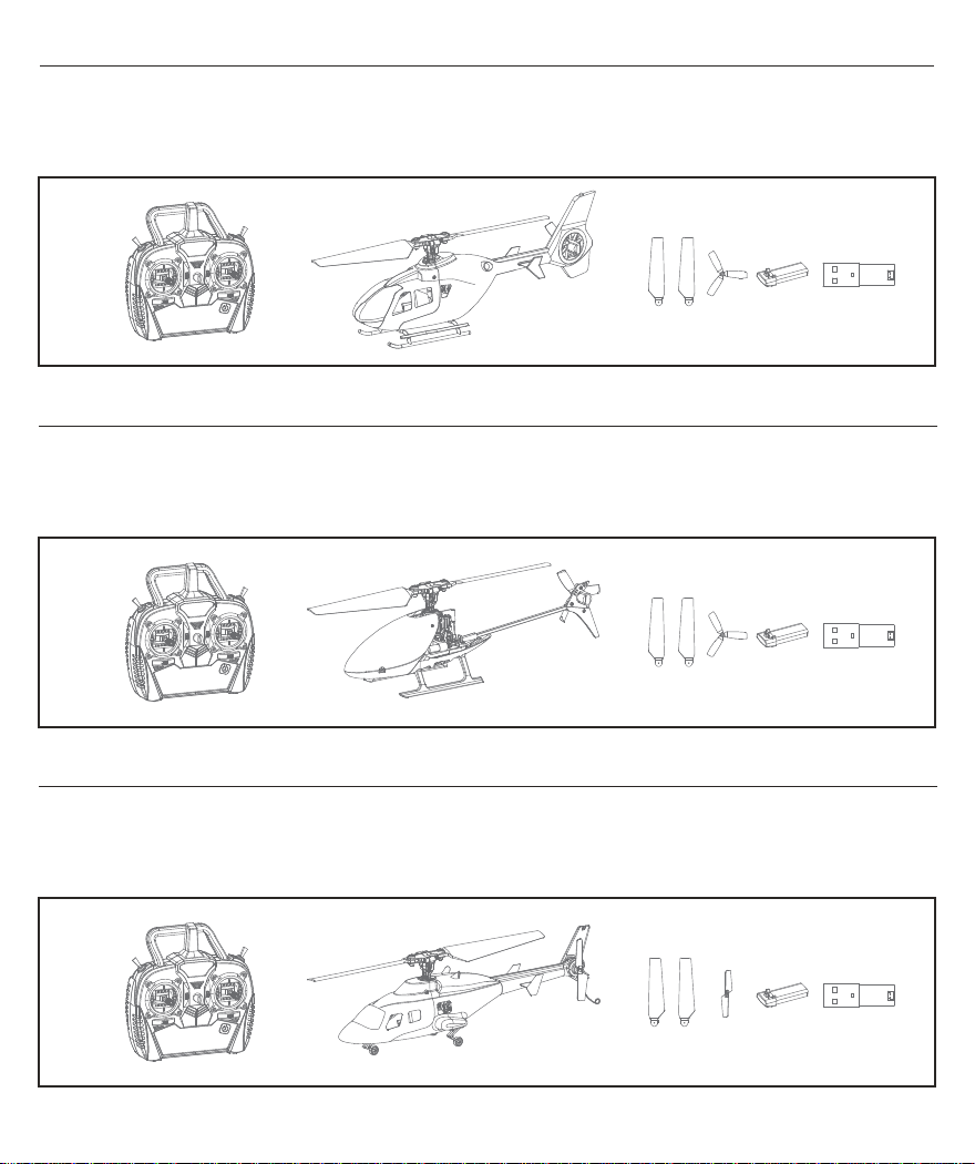
Box Contents (ESKY150EC)
EN
1 x ESKY 150 EC Helicopter
1 x 150mAh 1S 3.7V Li-Po Battery
1 x USB 1S Li-Po Charger
Box Contents (ESKY150V3)
1 x ESKY 150 V3 Helicopter
1 x 150mAh 1S 3.7V Li-Po Battery
1 x USB 1S Li-Po Battery
1 x MINI 6X 2.4Ghz Transmitter
2 x Main Blade
1 x Tail Blade
1 x MINI 6X 2.4Ghz Transmitter
2 x Main Blade
1 x Tail Blade
Box Contents (ESKY150BL)
1 x ESKY 150 BL Helicopter
1 x 150mAh 1S 3.7V Li-Po Battery
1 x USB 1S Li-Po Battery
1 x MINI 6X 2.4Ghz Transmitter
2 x Main Blade
1 x Tail Blade
3
Page 6
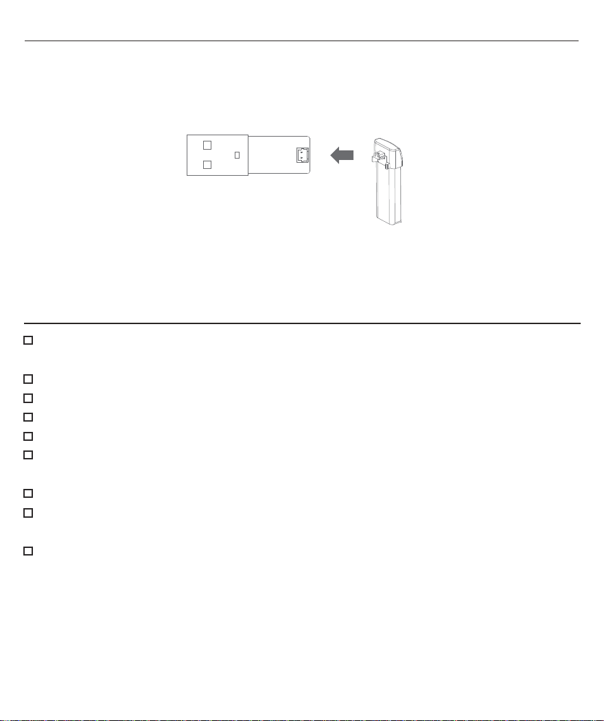
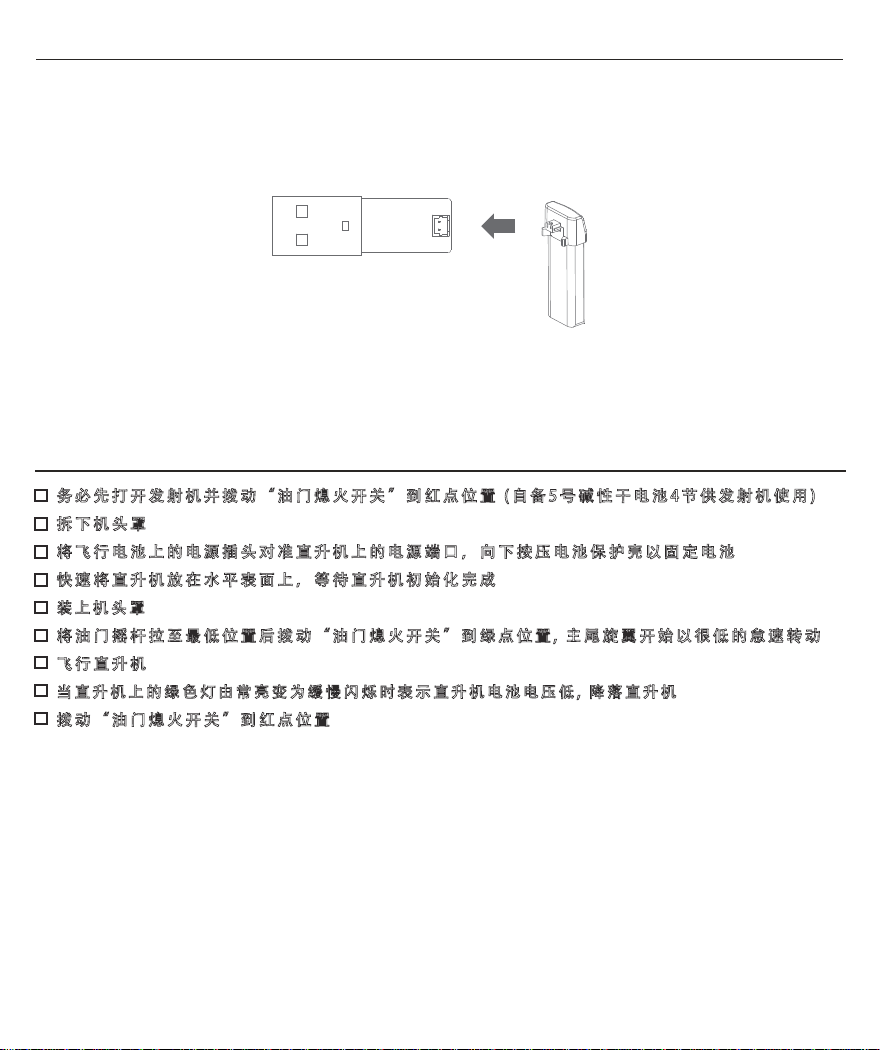
Battery Charging
1) Connect the 7.4 2S LiPo battery to the charger and connect the charger to the USB port.
2) The LED on the charger will glow solid red, indicating charging has begun.
3) The LED turns solid green when the LiPo battery is fully charged.
Soild Red: Charging
Soild Green: Charging completed / Power connected (Stand by)
EN
Flying Checklist
Always turn the transmitter on first and set the THROTTLE CUT switch to the RED dot position
(4 x AA size alkaline batteries are required for the transmitter)
Remove the canopy cover
Connect the flight battery in the helicopter and secure the battery by pressing down the battery case
Place the helicopter on a level surface and let it to initialize
Install the canopy cover
Lower the throttle stick to the lowest position and set the THROTTLE CUT switch in the transmitter to the
GREEN dot position (The motor will control by throttle and spin at low idle speed)
Fly the helicopter
The LED (Green) in the helicopter goes from solid to flashes slowly, indicating the flight battery voltage
is low, Land the helicopter
Set the THROTTLE CUT switch to the RED dot position
NOTICE: Be sure to set the THROTTLE CUT switch to the RED dot position after every flight.
Allow the helicopter to initialize and place the helicopter on a level surface. Initialization time is about 10 seconds,
initialize successfully until the LED Indicator in the helicopter from blue flashes rapidly to solid blue.
4
Page 7
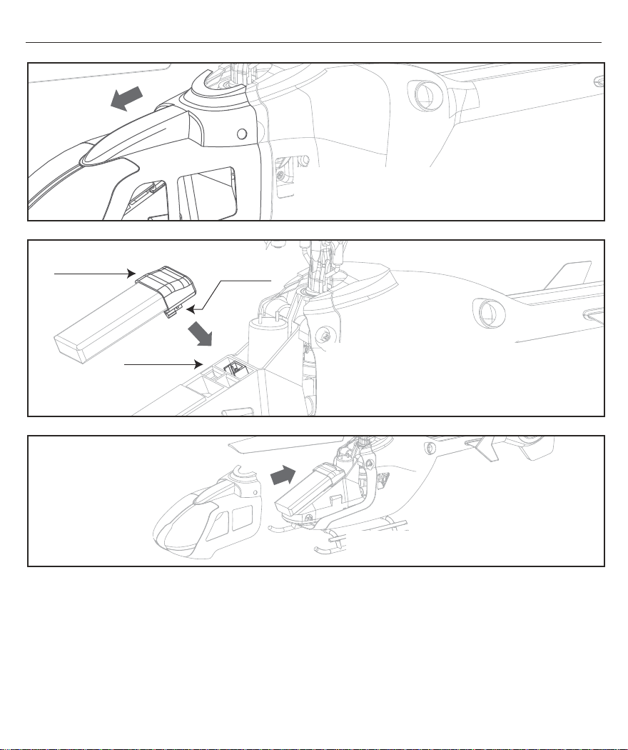
Install and Remove the Flight Battery
EN
The canopy cover is mounted on the canopy support rod
Gently pull the canopy cover forwards to remove
Battery Cover
Power Port
Battery plug
Align the battery plug on the flight battery
with the power port on the helicopter and
press down the battery cover to secure the battery
Install the canopy cover back on the helicopter
5
Page 8
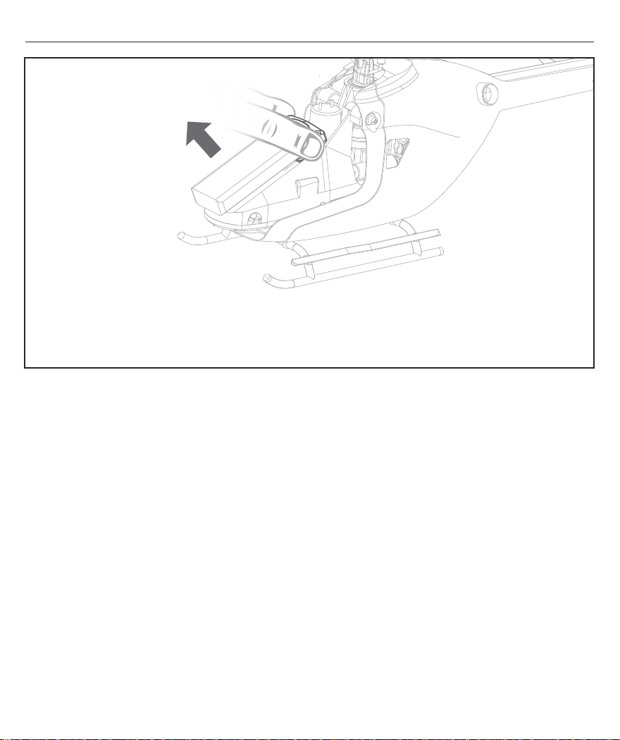
Install and Remove the Flight Battery
When removing the battery, please hold the left and right ends of the battery cover and pull out the battery
vertically upward. Do not shake the battery or pull it out in any other direction to avoid damaging the battery
power plug or the power port on the helicopter.
EN
6
Page 9
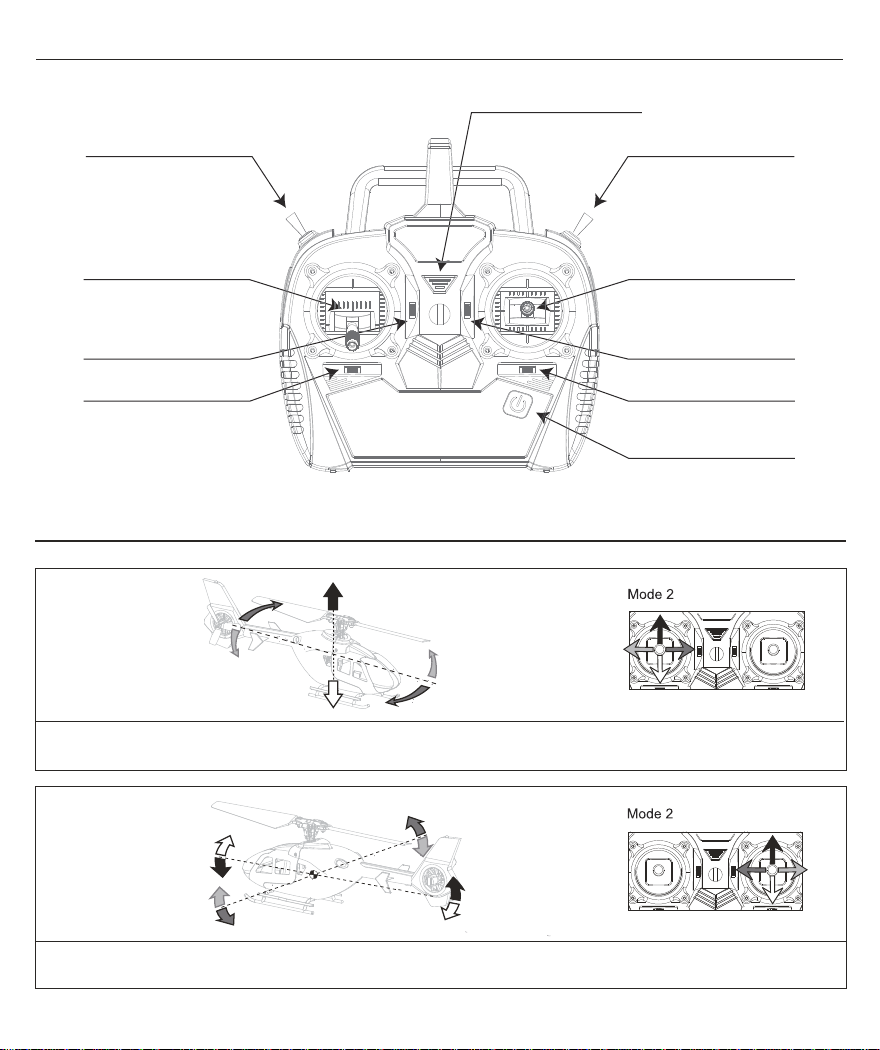
Transmitter Control (RTF Version) - Left hand throttle Mode 2
Power LED indicator
Mode Switch Throttle Cut Switch
EN
Rudder (Left/Right)
Throttle (Up/Down)
Throttle Trim
Rudder Trim
Aileron (Left/Right)
Elevator (Up/Down)
Elevator Trim
Aileron Trim
Power Switch
(Holding down for ON/OFF)
Understanding the Primary Flight Controls Mode 2
When pushing the “Left Stick” up or down, the helicopter lift or descend accordingly. This procedure is throttle control.
When pushing the “Left Stick” left or right, the head of the helicopter turns left or right accordingly. This procedure is rudder control.
When pushing the “Right Stick” up or down, the helicopter moves forward or backward accordingly. This procedure is elevator control.
When pushing the “Right Stick” left or right, the helicopter tilts left or right accordingly. This procedure is aileron control.
7
Page 10
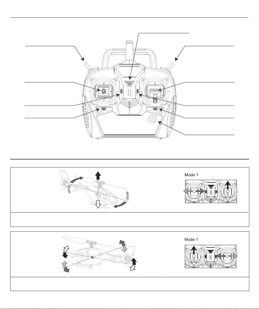
Transmitter Control (RTF Version) - Right hand throttle Mode 1
Power LED indicator
Throttle Cut Switch Mode Switch
EN
Rudder (Left/Right)
Elevator (Up/Down)
Elevator Trim
Rudder Trim
Aileron (Left/Right)
Throttle (Up/Down)
Throttle Trim
Aileron Trim
Power Switch
(Holding down for ON/OFF)
Understanding the Primary Flight Controls Mode 1
When pushing the “Right Stick” up or down, the helicopter lift or descend accordingly. This procedure is Throttle control.
When pushing the “Left Stick” left or right, the head of the helicopter turns left or right accordingly. This procedure is Rudder control.
When pushing the “Left Stick” up or down, the helicopter moves forward or backward accordingly. This procedure is Elevator control.
When pushing the “Right Stick” left or right, the helicopter tilts left ot right accordingly. This procedure is Aileron control.
8
Page 11
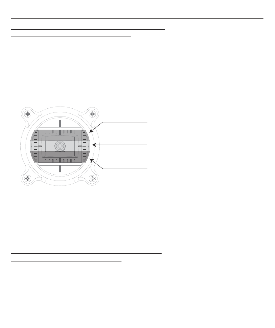
Mode Switch and Altitude Hold with Barometer
Switch to the LO mode that enables with the altitude hold feature
This mode is recommended for beginners (indoor)
1. Set the THROTTLE CUT switch to the GREEN dot position and push the throttle stick, helicopter will lift and
maintain a consistent altitude.
2. Pushing the throttle stick to the climb zone, the helicopter will lift at a constant speed and the LED (blue) in the
helicopter will go off.
3. Holding the throttle stick in the altitude hold zone, the helicopter will maintain at the current altitude and the LED
(blue) in the helicopter will glow solid.
4. Pulling down the throttle stick to the descent zone, the helicopter will descend at a constant speed and the LED
(blue) in the helicopter will turn off.
Climb Zone
Altitude Hold Zone
Descent Zone
EN
5. Lowering and holding the throttle stick to the lowest position, the helicopter will descend at a constant speed and
land on the ground.
6. Set the THROTTLE CUT switch to the RED dot position anytime to stop the main and tail blade from spinning.
Caution: The THROTTLE CUT switch must be set from RED to GREEN dot position before pushing the throttle stick
to lift the helicopter automatically.
Switch to the HI mode which is without the altitude hold feature
This mode is recommended for advance users
1. Set the THROTTLE CUT switch to the GREEN dot position and push the throttle stick, the helicopter will lift
accordingly.
2. Roll, pitch and rudder controls will be more sensitive and to fly faster.
3. Transmitter beep one time which shows is in HI mode.
9
Page 12
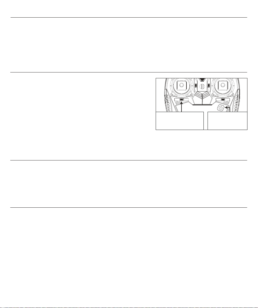
Throttle Cut
Throttle cut is used to turn off the motor quickly if the helicopter is out of control. The motor will stop spinning and
disable of throttle control when throttle cut is switched to RED dot position, the motor will continue to spin at low idle
speed and control by throttle when throttle cut is switched to GREEN dot position and the throttle at the lowest
position. If throttle cut is switched to GREEN dot position and the throttle position is NOT at lowest throttle, the motor
will still spin at low idle speed but out of throttle control until the throttle moves to the lowest throttle.
EN
Transmitter and Receiver Binding
1) Power off the transmitter and power on the helicopter, the LED
(Green) in the helicopter flashes rapidly which shows the helicopter
is in bind mode.
2) Push and hold the rudder trim to right, then press and hold the
power switch of the transmitter.
3) The LED (Green) in the helicopter will glow solid when binding is
complete. Then release the rudder trim button and power switch.
(Helicopter was completely bound in the factory setting.)
Push and hold the
Rudder Trim to the Right
Press and hold the
power switch
Transmitter Low Voltage Warning
The LED (Blue) flashes slowly when the transmitter battery voltage is low. Replace the transmitter battery as soon
as possible to prevent affecting normal operation.
When the LED (Blue) flashes slowly with beeps during flight, land the model and replace the transmitter battery
immediately. Failure to do so will probably result in destruction of the model and possibly bodily injury!
Maintenance Tool
Please use the provided screwdriver to install all the screws. Other tools can damage the screw and the helicopter.
10
Page 13
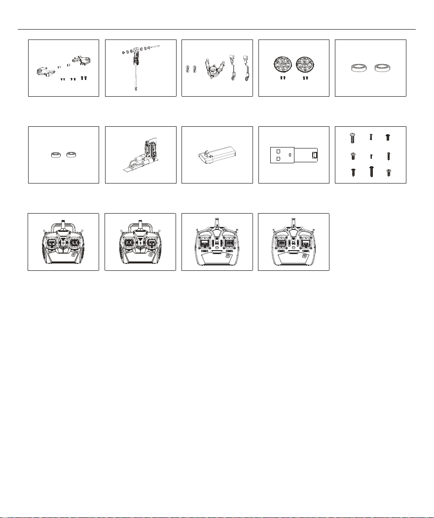
Common Parts Listing
EN
Main Rotor Blade Grip Set
Bearing Set (3*6*2)
MINI 6X Transmiter
(Mode 2)
ESKY008665ESKY008664 ESKY005805
Main Rotor Housing
ESKY008667ESKY005439 ESKY008668
Linear Servo Set USB Charger
MINI 6X Transmiter
(Mode 1)
Swashplate & Pushrod Set
Li-Po Battery
ESKY008725
ECH6 Transmiter
(Mode 2)
ESKY006311ESKY008666
Main Gear
ESKY006007ESKY005435c
ESKY008725aESKY008083 ESKY008083a
ECH6 Transmiter
(Mode 1)
Bearing Set (5*8*2)
Screws Set
11
Page 14
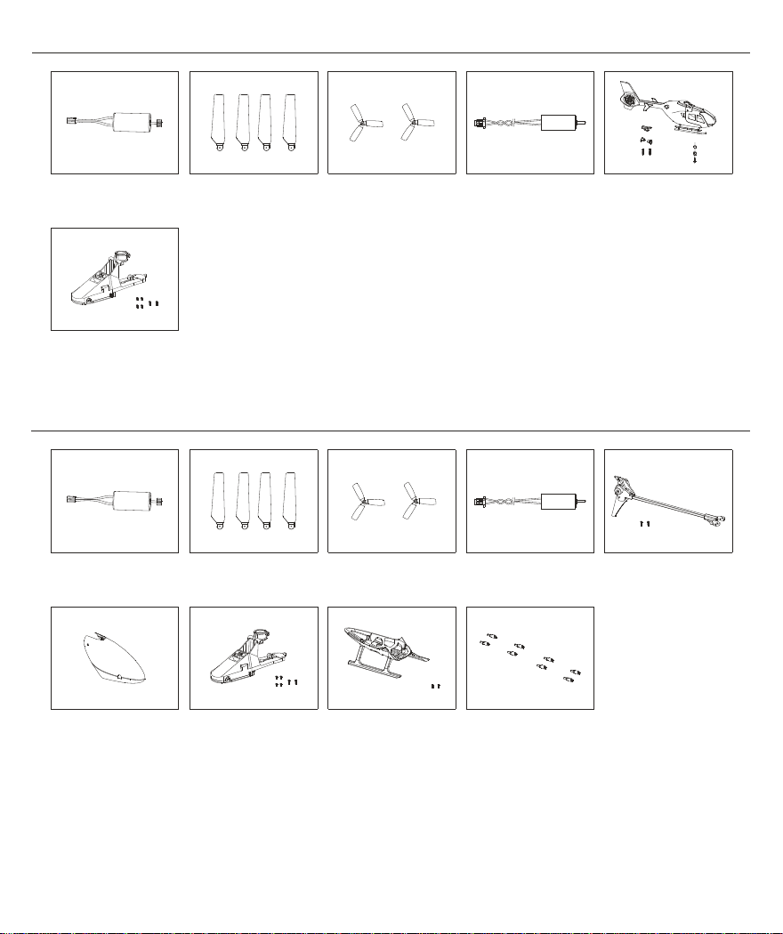
Dedicated Parts Listing (150EC)
EN
ESKY008717ESKY008880 ESKY008674
Main Motor
ESKY008662
Multi Control Unit
(150EC)
Main Blade Set Tail Motor
Dedicated Parts Listing (150V3)
ESKY008880
Main Motor Tail Blade
ESKY008717
Main Blade Set Tail Motor
Tail Blade
ESKY008885ESKY008900
Fuselage Set
(with Tail Motor & LED)
ESKY008882ESKY008669
ESKY008672
Tail Boom Set
(with Tail Motor & LED)
ESKY008671
Canopy Landing Skid
ESKY008661
Multi Control Unit
(150V3)
12
ESKY008673ESKY008676
Canopy Support Rod
Page 15
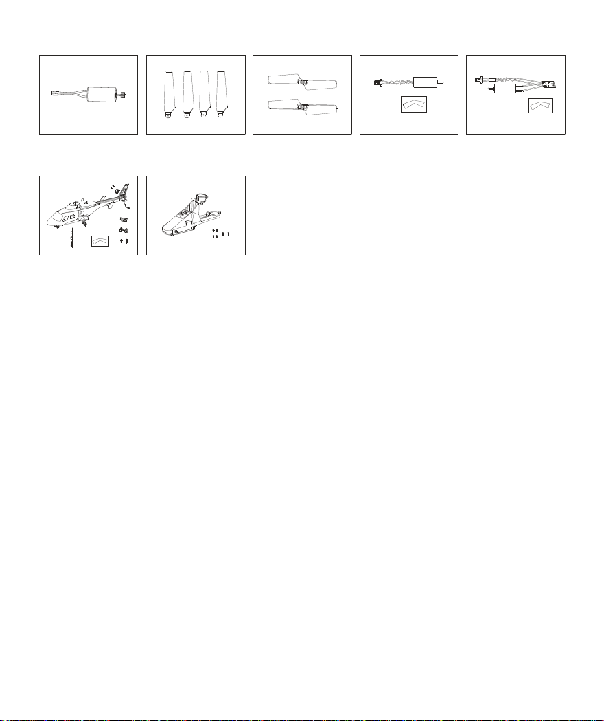
Dedicated Parts Listing (150BL)
EN
Main Motor
ESKY008675
Fuselage Set
(without Tail Motor & LED)
ESKY008718ESKY008881 ESKY008883
Main Blade Set Tail Motor
ESKY008663
Multi Control Unit
(150BL)
Tail Blade Set
ESKY008884ESKY006851
Tail Motor (with LED)
13
Page 16

*If you could not solve the problems by using the below methods*
Troubleshooting Guide
Problem: Battery bulges after several flight
Possible Cause: Keep the helicopter spinning when it can no longer be raised or over discharge the battery or long time not in use
(Solution: Replace with a new battery)
Problem: Green LED in the helicopter flashes slowly in flight
Possible Cause: LiPo battery low voltage (Solution: Recharge the LiPo battery)
Problem: Green LED in the helicopter flashes rapidly
Possible Cause: Helicopter in binding mode (Solution: Power off transmitter and repeat bind process)
Problem: Green LED in the helicopter goes off and blue LED in the helicopter glows solid
Possible Cause: Helicopter does not receive any signal from transmitter (Solution: Rebind or reboot the transmitter)
Problem: Green LED and blue LED in the helicopter are off
Possible Cause: Battery connection error or battery damaged (Solution: Reconnect the battery or change the new battery)
Problem: Motor does not spin after Initialize successfully but servo works normally
Possible Cause: Throttle cut function is activated (Solution: Set the throttle cut switch to GREEN in the transmitter)
Problem: Helicopter skewed slightly in flight
Possible Cause: Incorrect trim value (Solution: Maintain the helicopter level flight by adjusting the trim button)
Problem: Helicopter vibrates or shakes in flight
Possible Cause: Main rotor blade grip or main blade bent (Solution: Check them for damage and replace if necessary)
Problem: Helicopter spins rapidly in flight
Possible Cause: Tail blade installation direction was wrong (Solution: reinstall the tail blade with correct installation direction)
Problem: Helicopter skewed heavily in flight
Possible Cause
Possible Cause: Incorrect trim value in some direction (Solution: Set all the transmitter trim in the middle or neutral position)
Problem: How to judge whether the transmitter trim is in the moddle or neutral position?
Possible Cause: / (Solution: The middle or neutral trim position is heard as a longer tone)
: Servo or linking parts error (Solution: Check each linking parts)
*Please contact our service support team*
EN
14
Page 17

安全注意事项和警告
产品参数 & 直升机零件介绍 ...........................................................................
包装内容 ....................................................................................................
飞行电池充电方法 .........................................................................................
飞行操作步骤 ..............................................................................................
飞行电池安装与取下 .....................................................................................
左手发射机介绍 (RTF版本) - Mode 2 ...............................................................
右手发射机介绍 (RTF版本) - Mode 1 ................................................................
模式开关与油门辅助控制 ..............................................................................
油门熄火开关 ................................................................................................
对码方法 .....................................................................................................
发射机低电压报警 ........................................................................................
维修工具 .....................................................................................................
通用配件表 .................................................................................................
专用配件表 .................................................................................................
飞行中的异常排除 ........................................................................................
直升机模型是通过无线电信号控制的,在操作时可能会受到其他无线电信号干扰,此干扰可能会影响
直升机性能甚至会导致直升机失控。
1. 此遥控模型具有一定的危险性,禁止14岁以下人士进行操作!
2. 不要将产品直接暴露在火或者对温度有影响的热源下。
警 告
禁 止
3. 建议在5-35度,相对湿度20%-80%的环境中使用此产品。
4. 建议在没有风扇,冷气机,台灯或其他危险物件的地方操作此产品。
5. 电机为发热部件,请勿触摸,以免烫伤。
1. 飞行时要远离人群,避免旁人围观!以免误伤他人!
2. 直升机内部是由许多精密的电子零件组成,因此必须保证防潮防水,避免在浴室或
雨雾天气时使用,以免水气进入机体内部导致机器零件或电子零件故障而引发不可预
测的意外。
3. 请勿对直升机进行任何改装。
4. 直升机在飞行运转时禁止用手或其他物品触及直升机的任何部位!避免造成不必要
损失及人身伤害!
CN
目录
16
17
18
18
19
21
22
23
24
24
24
24
25
26
28
15
Page 18
产品参数 (ESKY 150EC - 蜂鸟)
宽度 ...................................
飞行重量 ...........................................
飞行时间 .......................................
宽度 ..............................................
飞行重量 ...........................................
飞行时间 .......................................
宽度 ..............................................
飞行重量 ...........................................
飞行时间 .......................................
CN
长度 ...........................................
高度 .............................................
主旋翼直径 ..................................
产品参数 (ESKY 150V3 - 教一)
长度 ...........................................
高度 .............................................
主旋翼直径 ..................................
产品参数 (ESKY 150BL - 小飞狼)
长度 ...........................................
高度 .............................................
主旋翼直径 ..................................
直升机零件介绍
主旋翼
179mm
68mm
168mm
179mm
62mm
168mm
186mm
59mm
168mm
..........
尾 旋翼
38mm
37g
约5分钟
44mm
36g
约6分钟
42mm
36g
约6分钟
机头罩
飞行电池
尾 马达
复合控制器
16
Page 19
包装内容 (ESKY 150EC - 蜂鸟)
CN
1 x 蜂鸟直升机
1 x 150mAh 1S 3.7V 锂电池
1 x USB 1S 锂电池充电器
包装内容 (ESKY 150V3 - 教一)
1 x 教一直升机
1 x 150mAh 1S 3.7V 锂电池
1 x USB 1S 锂电池充电器
1 x MINI 6X 2.4Ghz 发射机
2 x 主旋翼
1 x 尾旋翼
1 x MINI 6X 2.4Ghz 发射机
2 x 主旋翼
1 x 尾旋翼
包装内容 (ESKY 150BL - 小飞狼)
1 x 小飞狼直升机
1 x 150mAh 1S 3.7V 锂电池
1 x USB 1S 锂电池充电器
1 x MINI 6X 2.4Ghz 发射机
2 x 主旋翼
1 x 尾旋翼
17
Page 20
飞行电池充电方法
1) 将3.7V 1S 锂电池插入充电器,然后将充电器插入USB端口或USB电源。
2) 充电器上的红色灯常亮,表明充电已开始 。
3) 电池充满时,指示灯由红色常亮变为绿色常亮。
红色灯常亮:正在充电
绿色灯常亮:充电完成/电源已连接(待机)
飞行操作步骤
CN
务必先打开发射机并
拆下机头罩
将飞行电池上的电源插头对准直升机上的电源端口,向下按压电池保护壳以固定电池
快速将直升机放在水平表面上,等待直升机初始化完成
装上机头罩
将油门摇杆拉至最低位置后拨动“油门熄火开关”到绿点位置, 主尾旋翼开始以很低的怠速转动
飞行直升机
当直升机上的绿色灯由常亮变为缓慢闪烁时表示直升机电池电压低, 降落直升机
拨动“油门熄火开关”到 红点位置
注意事项:
每次飞行后请务必将发射机上的” 油门熄火开关” 拨动至红点位置。
在等待直升机初始化时请务必保持直升机静止状态。初始化时间约10秒,初始化时直升机蓝色灯
快速闪烁, 初始化完成后蓝色灯由快速闪烁变为常亮。
拨动“油门熄火开关”到 红点位置 (自备5号碱性干电池4节供发射机使用)
18
Page 21
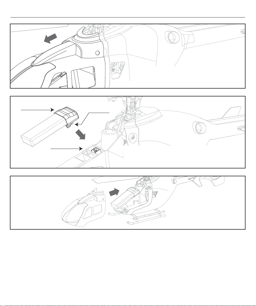
飞行电池安装与取下
CN
注意!机头罩是安装在机壳支撑杆上
向外轻抠机头罩即可取出,无需拆卸固定螺丝
电池保护壳
电池插头
电源端口
确保电池上的电源插头对准直升机上的电源端口
再按压电池保护壳, 以免损坏电池或复合控制器
将机头罩装回到机身中
19
Page 22
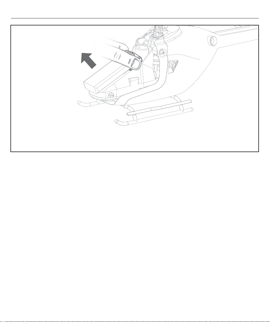
飞行电池安装与取下
请勿摇晃电池或从其他方向施力拔出电池,以免损坏电池电源插头或直升机上的电源端口
CN
注意!取下电池时请握住电池保护壳左右两端并垂直向上拔出电池
20
Page 23
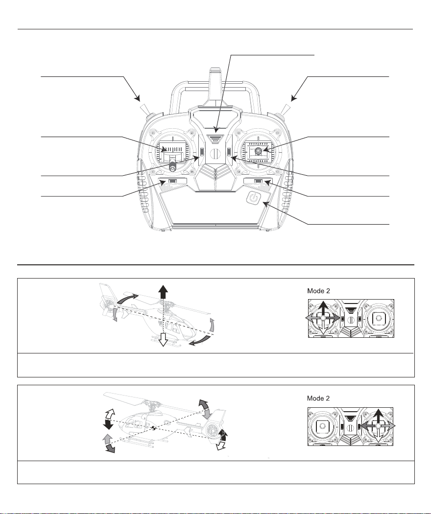
左手发射机介绍 - Mode 2
CN
电源指示灯
模式开关
航向 (左/右)
油门 (上/下)
油门微调
航向微调
左手发射机控制说明 Mode 2
油门熄火开关
侧滚 (左/右)
俯仰 (上/下)
俯仰微调
侧滚微调
电源开关(长按开关机)
当"左摇杆"向上推动时,直升机转速加快并上升;当"左摇杆"向下推动时,直升机转速减慢并下降;此过程是油门控制。
当"左摇杆"向左推动时,直升机机头向左转;当"左摇 杆"向右推动时,直升机机头向右转;此过程是航向控制。
当"右摇杆"向上推动时,直升机低头并向前飞行;当"右摇杆"向下推动时,直升机抬头并向后飞行;此过程是俯仰控制。
当"右摇 杆"向左推动时,直升机向左倾斜飞行;当"右摇杆"向右推动时,直升机向右倾斜飞行;此过程是侧滚控制。
21
Page 24
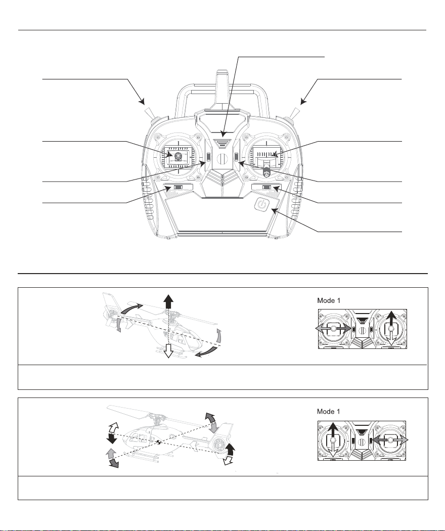
右手发射机介绍 - Mode 1
电源指示灯
油门熄火开关模式开关
CN
航向 (左/右)
俯仰 (上/下)
俯仰微调
航向微调
侧滚 (左/右)
油门 (上/下)
电源开关
油门微调
侧滚微调
(长按开关机)
右手发射机控制说明 Mode 1
当"右摇杆"向上推动时,直升机转速加快并上升;当"右摇杆"向下推动时,直升机转速减慢并下降;此过程是油门控制。
当"左摇 杆"向左推动时,直升机机头向左转;当"左摇杆"向右推动时,直升机机头向右转;此过程是航向控制。
当"左摇杆"向上推动时,直升机低头并向前飞行;当"左摇杆"向下推动时,直升机抬头并向后飞行;此过程是俯仰控制。
当"右摇杆"向左推动时,直升机向左倾斜飞行;当"右摇杆"向右推动时,直升机向右倾斜飞行;此过程是侧滚控制。
22
Page 25
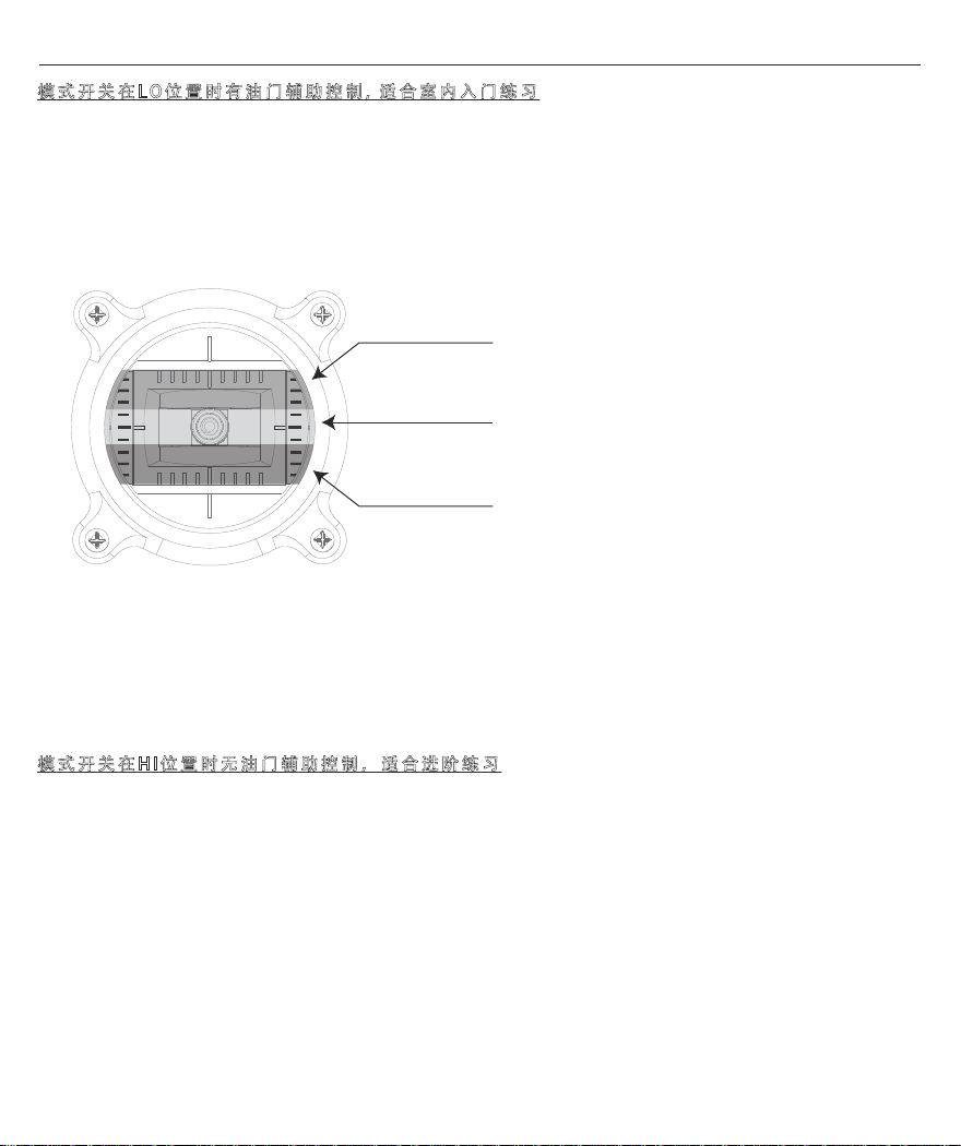
模式开关与油门辅助控制
模式开关在LO位置时有油门辅助控制, 适合室内入门练习
1)模式开关在LO位置时, 拨动” 油门熄火开关” 到 绿点位置后推动油门摇杆, 直升机将自动上升至固定
高度并悬停。
2)推动油门摇杆至上升区时直升机将以固定速度匀速上升, 直升机上的蓝色灯熄灭。
3)油门摇杆在定高区时直升机将保持当前高度并稳定悬停,直升机上的蓝色灯常亮。
4)拉动油门摇杆至下降区时直升机将以固定速度匀速下降, 直升机上的蓝色灯熄灭。
上升区
定高区
下降区
5)将油门摇杆拉至最低位置并保持, 直升机将匀速下降至地面。
6)任何时候拨动” 油门熄火开关” 到红点位置, 主尾旋翼停止转动。
CN
注意: 每次推动油门摇杆让直升机自动上升前, ” 油门熄火开关” 需由红点位置拨至绿点位置。
模式开关在HI位置时无油门辅助控制,适合进阶练习
1)模式开关在HI位置时, 拨动” 油门熄火开关” 到 绿点位置后推动油门摇杆, 直升机将跟随油门摇杆变
化加速或减速上升。
2)侧滚、俯仰以及航向的控制更加灵敏, 飞行速度也更快。
3)模式开关拨至HI位置,发射机会发出” 嘟 ”一声,表示当前模式为进阶练习。
23
Page 26
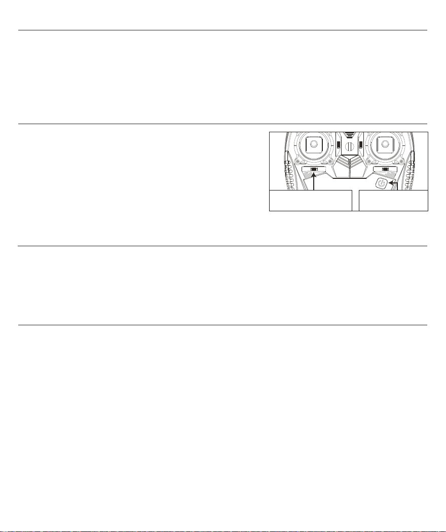
油门熄火开关
当直升机失去控制时油门熄火开关可用于快速关闭电机。油门熄火开关拨至红点位置时电机将停止转
动并不受油门摇杆控制, 油门熄火开关拨至绿点位置并且油门摇杆处在最低位置时, 电机将怠速转动
并可被油门摇杆控制。当熄火开关拨至绿点位置并且油门摇杆处在高位时, 电机将怠速转动但不受油
门摇杆控制, 直至油门摇杆被拉至最低位置。
CN
对码方法
1)关闭发射机电源并打开直升机电源,直升机中的绿色
灯会在短时间内快速闪烁。
2)向右推航向微调键并保持, 同时打开发射机电源。
3)当直升机的绿色灯常亮时,表示对码完成,松开航向
微调键。
(直升机在出厂时已对好码)
将此微调往右推
按住电源开关
发射机低电压报警
当发射机电池电压变低时,蓝色电源指示灯缓慢闪烁。请尽快更换发射机电池,以免影响正常操作。
飞行期间,如果发射机蓝色电源指示灯缓慢闪烁并发出哔哔声,请降落直升机并立即更换发射机电池
。否则可能会损坏直升机甚至造成人身伤害!
维修工具
为保证直升机中所有螺丝既可以被正确锁紧又不会因过度用力而导致螺丝滑牙,请务必使用随产品提
供的维修工具进行维修保养操作。
24
Page 27
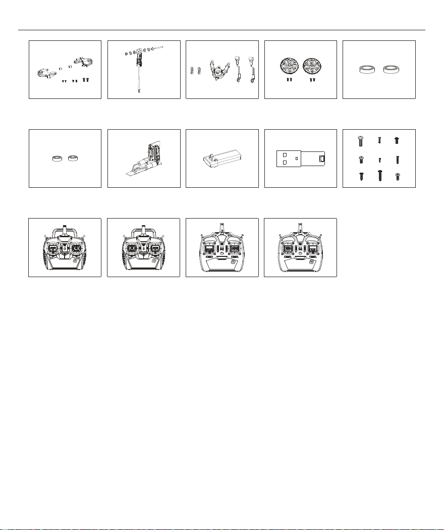
通用配件表 (150EC - 蜂鸟 / 150V3 - 教一 / 150BL - 小飞狼)
主翼夹头组
轴承组3*6*2
MINI 6X发射机
(左手油门)
ESKY008665ESKY008664ESKY005805
主旋转头组主齿轮
ESKY008667ESKY005439ESKY008668
直线舵机组USB充电器
MINI 6X发射机
(右手油门)
倾斜盘&拉杆组
锂电池
ESKY008725
ECH6发射机
(左手油门)
ESKY006311ESKY008666
轴承组5*8*2
ESKY006007ESKY005435c
螺丝组
ESKY008725aESKY008083ESKY008083a
ECH6发射机
(右手油门)
25
Page 28
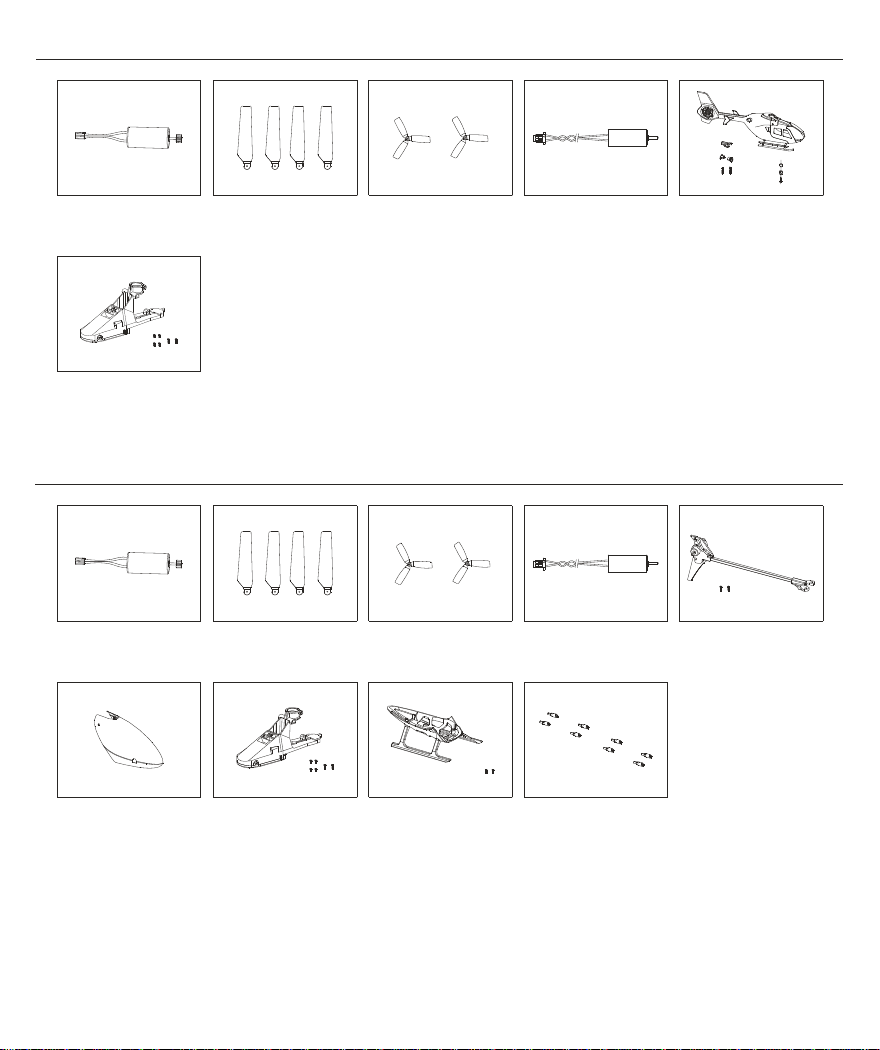
专用配件表 (150EC - 蜂鸟)
ESKY008717ESKY008880ESKY008674
主马达
ESKY008662
复合控制器(蜂鸟)
主翼组尾马达
专用配件表 (150V3 - 教一)
ESKY008880
主马达尾旋翼
ESKY008717
主翼组尾马达
尾旋翼
ESKY008885ESKY008900
机身组
(含尾马达及尾灯)
ESKY008882ESKY008669
ESKY008672
尾架组
(含尾马达及尾灯)
ESKY008671
机头罩滑橇
ESKY008661
复合控制器(教一)机壳支撑杆
ESKY008673ESKY008676
26
Page 29
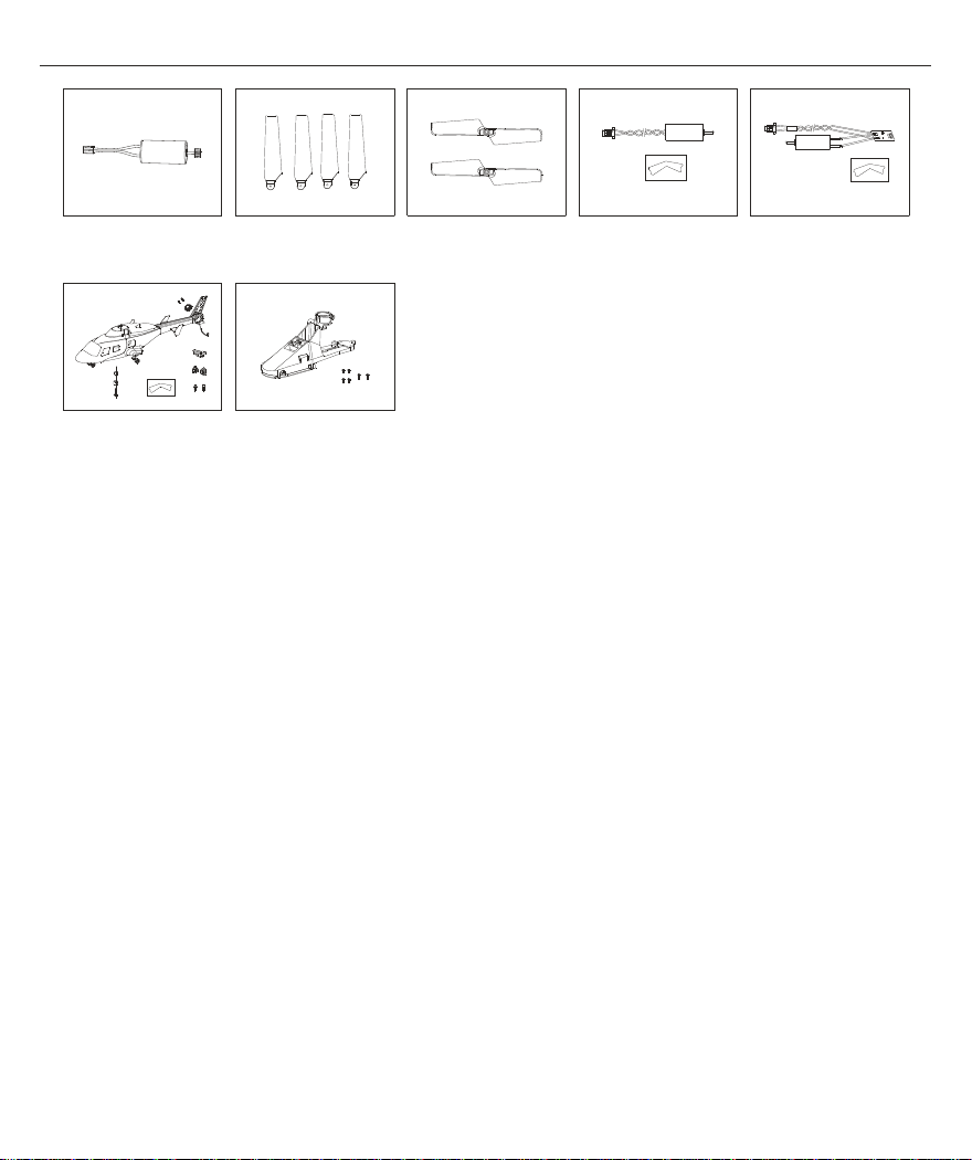
专用配件表 (150BL - 小飞狼)
主马达
ESKY008675
机身组
(不含尾马达及尾灯)
ESKY008718ESKY008881ESKY008883
主翼组尾马达
ESKY008663
复合控制器(小飞狼)
尾旋翼
ESKY008884ESKY006851
尾马达( 含尾灯)
27
Page 30
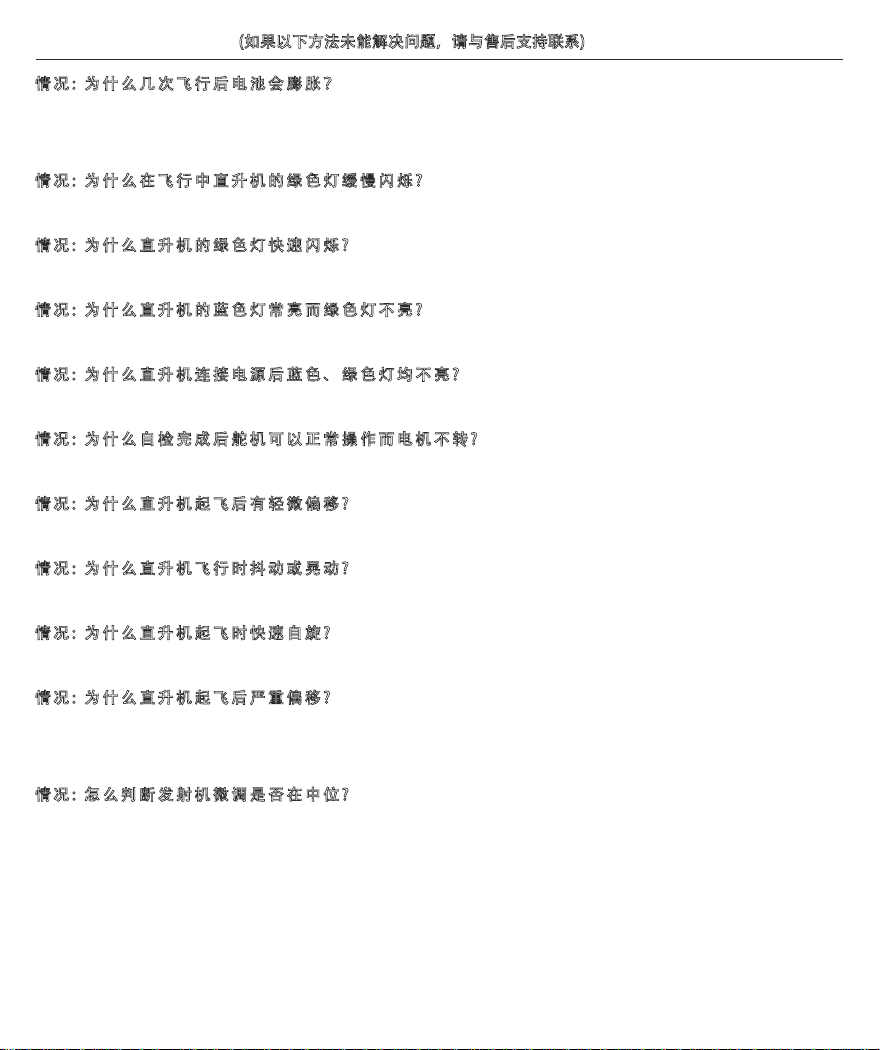
飞行中的异常排除 (如果以下方法未能解决问题,请与售后支持联系)
情况: 为什么几次飞行后电池会膨胀?
原因: 直升机己经不能升起时继续让直升机保持转动或其他原因导致电池过放或长时间不使用未做维护
(解决方法: 更换新电池)
情况: 为什么在飞行中直升机的绿色灯缓慢闪烁?
原因: 电池电压过低 (解决方法: 为锂电池充电)
情况: 为什么直升机的绿色灯快速闪烁?
原因: 直升机进入对码状态 (解决方法: 按操作步骤重新操作或重新对码)
情况: 为什么直升机的蓝色灯
原因: 直升机未收到发射机信号 (解决方法: 重启发射机或重新对码)
情况: 为什么直升机连接电源后蓝色、绿色灯均不亮?
原因: 电源连接异常或电池异常 (解决方法: 重新连接直升机电源或更换电池)
情况: 为什么自检完成后舵机可以正常操作而电机不转?
原因: 操作步骤错误直升机进入安全保护状态 (解决方法: 按操作步骤进行正确操作)
情况: 为什么直升机起飞后有轻微偏移?
原因: 微调修正不正确 (解决方法: 使用微调修正)
情况: 为什么直升机飞行时抖动或晃动?
原因: 主旋转头或旋翼变形 (解决方法: 检查主旋转头或旋翼并更换)
情况: 为什么直升机起飞时快速自旋?
原因: 尾旋翼有异物或更换尾翼时安装方向错误 (解决方法: 清除尾旋翼异物或更换尾翼安装方向)
情况: 为什么直升机起飞后严重偏移?
原因: 舵机或结构联动件异常 (解决方法: 检查直升机各部份工作状态)
原因: 微调往一个方向调整过多 (解决方法: 将对应方向微调回归中位后再进行微调操作)
情况: 怎么判断发射机微调是否在中位?
原因: / (解决方法: 微调回归中位后发射机会发出哔一声长响)
常亮而绿色灯不亮?
CN
28
Page 31

Page 32
All instructions are subject to change at the sole discretion of Zonda Hobby.
For up-to-date product literature, visit esky-rc.com and click on the support tab for this product.
忠达模型保留更改所有说明的权利,说明及其它附属资料的变更将不另行通知。
如需更新或获取更多资讯,请访问esky-rc.com.cn
Created 11/22
 Loading...