

ESK Schultze ERM2, ERHD Installation And Operating Instructions Manual

Montage- und Betriebsanleitung
Installation and operating instructions
MADE IN GERMANY
Elektronische Ölspiegelregulatoren ERM2 / ERHD
Die genannten ESK-Komponenten sind ausschließlich
für die Anwendung in Kälteanlagen bestimmt.
Sie entsprechen der EG-Druckgeräterichtlinie 97/23/EG.
Eine Inbetrieb nahme ist nur unter der Voraussetzung
zulässig, dass der Einbau entsprechend den gesetzlichen
Vorschriften erfolgte. Alle Komponenten werden entsprechend den geltenden Regeln konstruiert und gefertigt.
AD-Merkblätter; Druckgeräterichtlinie; EN 378
Das Produkt erfüllt folgende Bestimmungen:
▪ EMV Richtlinie 2004 / 108 / EG,
▪ Niederspannungsrichtlinie 2006 / 95 / EG
▪ R oH S R ic h tl i n ie 2 011 / 6 5 / EG .
Electronic Oil Level
Regulators ERM2 / ERHD
The ESK components mentioned shall be used
in refrigeration plants exclusively.
They correspond to EU-Pressure Equipment Directive
97/23/EG. Operation is only permitted if the installation
was carried out in accordance with legal regulations.
All components are constructed and produced in accordance with the regulations in force.
AD leaflets; pressure equipment guideline; EN 378
The product fulfils the Regulations of
▪ the EMC-Directive 2004 / 108/ EC,
▪ the Low Voltage Directive 2006 / 95 / EC
▪ the RoHS-Directive 2011 / 65 / EC.
Typ / Type ERM2-OC
und /and ERM2-0-BC
Produkteigenschaften
Aufbau: Regulatorkörper aus Aluminium
Große Zuströmquerschnitte
Elektronikgehäuse aus Kunststoff
Schauglas für visuelle Füllstandskontrolle
Druck- und dichteunabhängige Istwert-
erfassung des Füllstandes
Regelniveau: Mitte Schauglas
Opto-elektronisches Messverfahren
Zwei Relais zur Signalisierung und
Aufzeichnung von Betriebszuständen
Sicherheit:
durch verschmutztes Öl
Integriertes Notlaufprogramm sorgt selbst bei
widrigsten Umständen für die Ölversorgung
Vierfach-Messpunkte ermöglichen die Signalüber-
wachung von Unter-, aber auch Überfüllung
Alarmfunktion bei Über-, Unterfüllung
und bei aktiviertem Notlaufprogramm
씮 www.esk-schultze.de
Verstärkte LEDs führen zu verringerter Anfälligkeit
Product Features
Design: Regulator case made of aluminium
Wide cross sections for oil flow
Electronic case made of plastic
Sight glass for visual oil level control
Actual level value detection independent of
pressure and density
Control level: middle sight glass
Opto-electronical measuring method
Two relays for signalisation / recording of
system operating conditions
Security:
caused by contaminated oil
Integrated emergency operation program arranges
for oil feed even in adverse conditions
Quadruple measure points enable signal control
of under- but also overfilling
Alarm function for over-, underfilling and for
activated emergency operation program
Reinforced LEDs lead to reduced sensitivity
1/8
www.esk-schultze.de
Elektronische Ölspiegelregulatoren
Electronic Oil Level Regulators
Anwendung
Beim Verbundbetrieb von Verdichtern werden Ölspiegelregulatoren zur Ölniveauregelung an die Verdichter angebaut. Die Ölzufuhr
erfolgt aus einem Ölsammelgefäß.
Für die korrekte Funktion des elektronischen Regulators ist die
leistungsmäßig richtige Auslegung aller Systemkomponenten
Application
In multiple-compressor parallel systems oil level regulators are
installed to maintain an adequate oil level. Oil is fed conventionally from an oil reservoir.
The performance-oriented choice of all components will guarantee the regular function of the electronic oil level regulator.
wichtig.
Technische Daten
Getakteter Füllvorgang ERM2-...: Füllen: 3 s
Messen: 10 s
Getakteter Füllvorgang ERHD-...: Füllen: 1 s
Messen: 10 s
Max. zul. Umgebungstemperatur: 45° C
Max. zul. Öl-/ Mediumtemperatur: 85° C
Spannungsversorgung: 230 V 50/60 Hz – 1Ph ± 10 %
Alarmrelaisbelastung: 250 V / 5 A
Schutzart: IP 54
Gewicht: 1,3 kg
Kältemittel: HFKW / HFCKW / CO2 (R744)
Technical Data
Pulsed oil refilling process ERM2-...: Filling: 3 sec
Measuring: 10 sec
Pulsed oil refilling process ERHD-...: Filling: 1 sec
Measuring: 10 sec
Max admiss. ambient temp.: 45° C
Max admiss. oil temperature: 85° C
Power supply: 230 V 50/60 Hz – 1Ph ± 10 %
Load. alarm relay max.: 250 V / 5 A
Protection: IP 54
Weight: 1,3 kg
Refrigerants: HFC / HCFC / CO2 (R744)
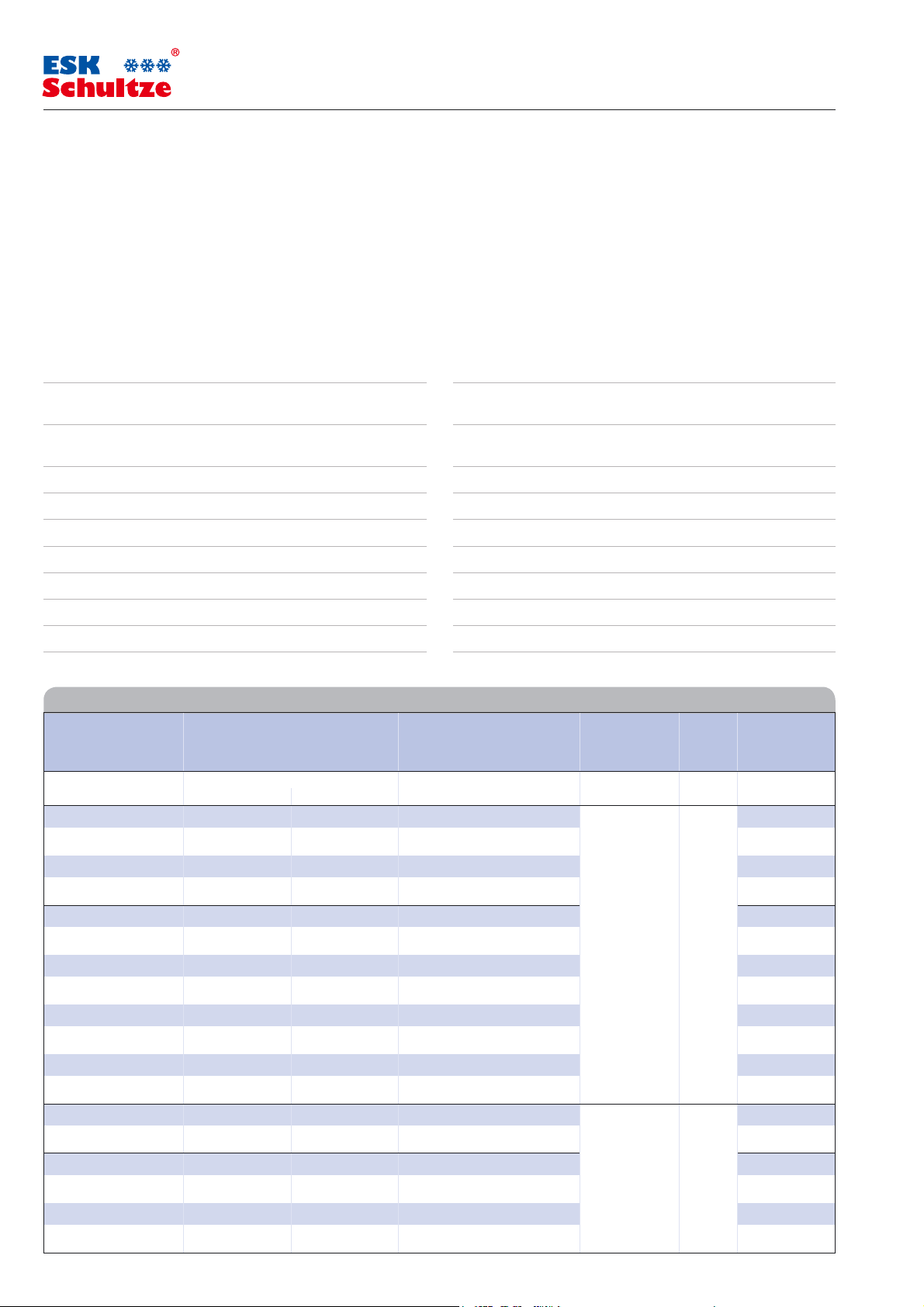
Technische Daten Technical Data
Elektronischer Arbeitsdruckdifferenz Verdichter-Anschluss Max. zulässiger Volumen Abmessungen
Ölspiegelregulator Empfohlener und max. zulässiger Wert Ausführung Arbeitsdruck
Electronic Working pressure difference Compressor Connection Max. admissible Volume Dimensions
Oil Level Regulator Recommended and max. admiss. value Version working pressure
Typ Abb. A B
Type Fig. bar bar bar l (dm³) mm mm
ERM2-0-BC a 1,5 4,5 3/4-Loch / 3/4-bolt 79 146
ERM2-0-BC-S a 1,5 4,5 3/4-Loch / 3/4-bolt 44 111
ERM2-OC b 1,5 4,5 Gewinde / Thread (1.1/8“-18 UNEF) 58 125
ERM2-SN b 1,5 4,5 Gewinde / Thread ( 3/4“-14 NPT ) 45 0,2 58 125
ERHD-0-BC a 2 – 20 20,0 3/4-Loch / 3/4-bolt 79 146
ERHD-0-BC-S a 2 – 20 20,0 3/4-Loch / 3/4-bolt 44 111
ERHD-0-BC-NW1 a 2 – 25 25,0 3/4-Loch / 3/4-bolt 79 146
ERHD-OC b 2 – 20 20,0 Gewinde / Thread (1.1/8“-18 UNEF) 58 125
ERHD-OC-NW1 b 2 – 25 25,0 Gewinde / Thread (1.1/8“-18 UNEF ) 58 125
ERHD-OC-B c 2 – 20 20,0 Gewinde / Thread (1.1/8“-18 UNEF) 58 125
ERHD-OC-B-NW1 c 2 – 25 25,0 Gewinde / Thread (1.1/8“-18 UNEF) 58 125
ERHD-SN b 2 – 20 20,0 Gewinde / Thread (3 /4“-14 NPT) 58 125
ERM2-0-BC-CDM a 1,5 4,5 3/4-Loch / 3/4-bolt 79 146
ERM2-OC-CDM b 1,5 4,5 Gewinde / Thread (1.1/8“-18 UNEF) 58 125
60 0,2
ERHD-0-BC-CDM a 2 – 20 20,0 3/4-Loch / 3/4-bolt 60 0,2 79 146
ERHD-OC-CDM b 2 – 20 20,0 Gewinde / Thread (1.1/8“-18 UNEF) 58 125
ERHD-OC-NW1-CDM b 2 – 25 25,0 Gewinde / Thread (1.1/8“-18 UNEF) 58 125
ERHD-OC-B-CDM c 2 – 20 20,0 Gewinde / Thread (1.1/8“-18 UNEF) 58 125
45 0,2
2/8
씮 www.esk-schultze.de
110
83
72
155
4968
84
B
A
110
83
72
155
4968
84
B
A
110
83
72
155
68 49
84
B
A
M16
M20
M16
M20
M16
M20
4
1
2
3
1
2
3
1
2
3
4
Elektronische Ölspiegelregulatoren
Electronic Oil Level Regulators
MADE IN GERMANY
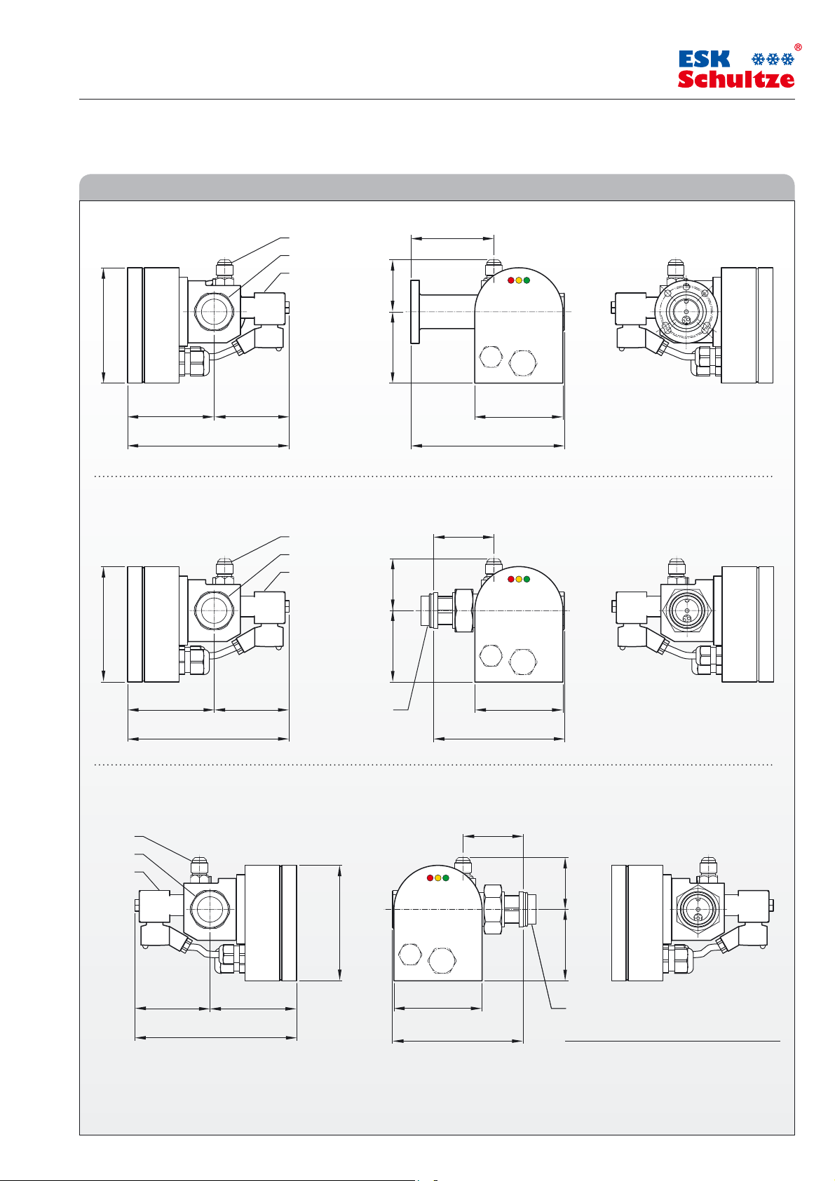
Maßzeichnungen Dimensional Drawings
Abbildung /
Figure a
Abbildung /
Figur
e b
Abbildung /
Figure c
1 Öleintritt Ø 10 mm Oil inlet Ø 10 mm
2 Schauglas Sight Glass
3 Magnetventil Solenoid Valve
4 Adapter OC bzw. SN Adapter OC or SN
씮 www.esk-schultze.de
3/8
 Loading...