

Eskridge 77 Series, 77BD, 77BA Series, 77BC Service & Repair Manual
PART NUMBER EXAMPLE: 77BA - 3 2 F 59
SERIES
Series 77 Planetary Digger
Service & Repair Manual
EFFECTIVE FOR:
S/N: 17000 - UP
DATE: 08/01/92 - UP
OUTPUT
SHAFT
BAIL BOSS
MOTOR
SUPPLIER
MOTOR
NO.
Drive
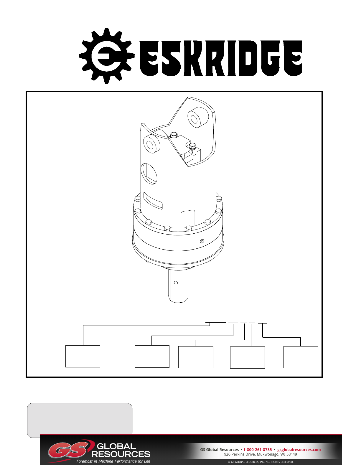
SERIES 77 SERVICE MANUAL
SINGLE SPEED
PLANETARY DIGGERDRIVE
This manual will assist in disassembly and assembly of the above series planetary Auger Drive. Item numbers,
indicated in parentheses throughout this manual, refer to the exploded parts breakdown drawing. Individual customer
specifications (bail assembly, output shaft, hydraulic motor, etc.) may vary from exploded drawing and standard part
numbers shown. If applicable, refer to individual customer drawing for details.
For any spare or replacement parts, contact your distributor or equipment manufacturer. Always try to have available the
auger unit part number, serial number and date code on the serial tag. This information may be necessary for verification
of any component part numbers. Component part numbers and/or manufacturing lot numbers may be stamped on
individual parts. This information may also be helpful in identifying replacement components.
LUBRICATION AND MAINTENANCE
Change the oil after the first 50 hrs. of operation. Oil should be changed at 500 hr. intervals thereafter. Gearboxes in auger
drives require GL-5 grade EP 80/90 gear oil for lubrication. The manufacturer recommends that the unit be partially
disassembled to inspect gears, splines, and bearings at 1000 hour intervals.
OIL CAPACITY: 6.5 pints
Proper oil level will measure to middle of primary cluster gears when auger drive is in vertical position.
For checking the oil in fully assembled units, see instructions on page 11.
WARNING: While working on this
equipment, wear adequate protective
clothing, hearing, eye, and respiratory
protection. Use safe lifting procedures.
UNIT DISASSEMBLY
(Refer to exploded view drawing on page 7)
1) Scribe a diagonal line, from the bail assembly (20) to the
bearing carrier (2), across the outside of the auger drive to
assure proper orientation of parts as they are re-assembled.
2) To drain oil, position unit on its side and remove oil plug
(41) located in the top case (1). To help ventilate oil while
draining, loosen hydraulic motor bolts (31)
drainage occurs when oil is warm.
NOTE: Particular care should be taken when placing the
unit in a position for servicing. Unit should be blocked up
so that weight of the unit is resting on the bearing carrier
(2). This fixture must be secure so that the auger drive will
not tip over during disassembly and assembly procedures.
. Maximum
4) Remove the two cap screws (31) and lock washers (40)
from hydraulic motor (50). Remove motor from unit.
Check o-ring (43) for damage.
5) Remove top case (1), input gear (14), and o-ring (44).
6) Lift the primary planet carrier assembly out of the unit
(includes items 7,9,11,17,23, & 33).
7) If sun gear (12) has not been removed from auger drive,
do so now. (Sometimes the sun gear remains in the
primary carrier (7).)
8) Remove secondary ring gear (4) and o-ring (44).
9) Remove retaining ring (37) from end of output shaft (49).
10) Lift the secondary planetary assembly out of the unit
(includes items 6,8,10,18,24, & 33). Use a puller if
needed.
11) The unit is now disassembled into groups of parts. The
area(s) requiring repair should be identified by thorough
inspection of the parts after they have been cleaned and
dried. Then refer to the appropriate group repair section
below.
3) Remove the twelve hex head cap screws (29) and hex
flange nuts (34) from bail assembly (20). Lift bail assembly
from unit.
NOTE: There are no bolts retaining the major components
2
together. Proceed with caution when moving the unit.
CAUTION: Output shaft is not retained at this point.
1. Primary Planet Carrier subassembly
2. Secondary Planet Carrier subassembly
3. Top case subassembly
4. Base subassembly
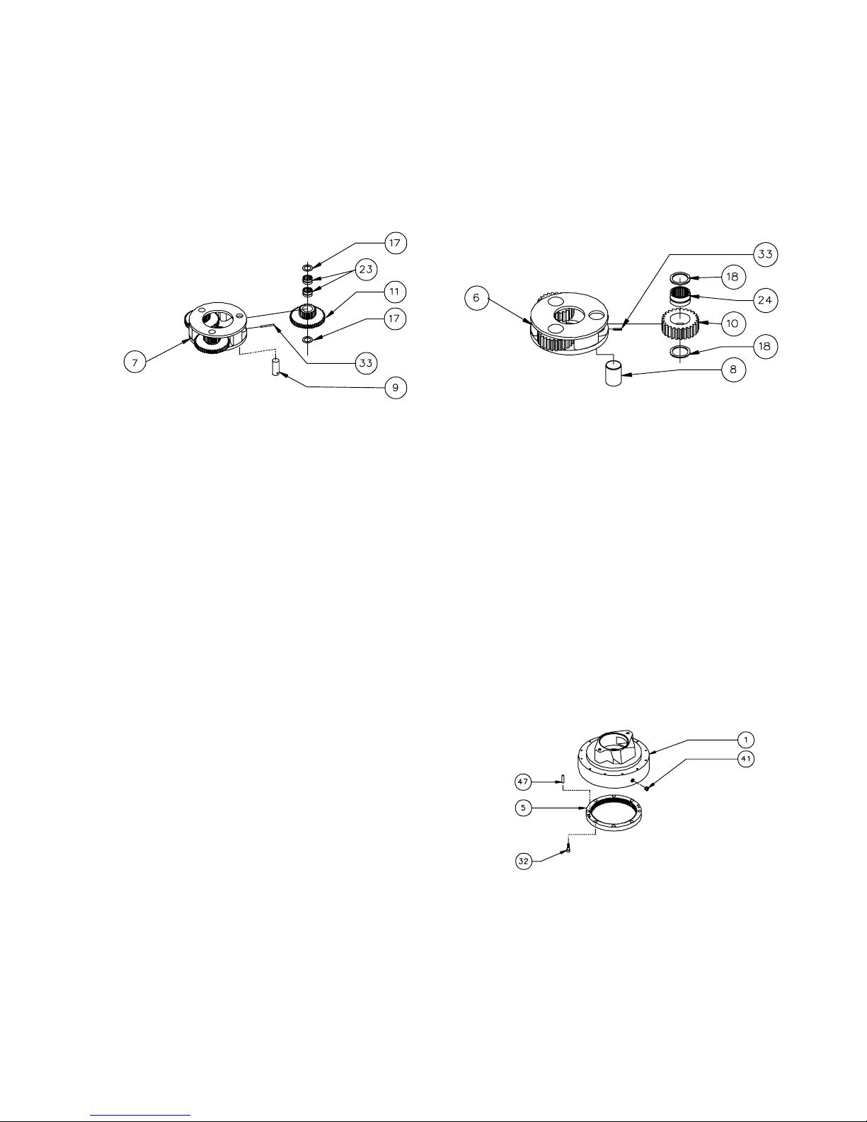
PRIMARY
SECONDARY
PLANET CARRIER
SUBASSEMBLY
(ITEMS 7,9,11,17,23, & 33)
DISASSEMBLY AND REPAIR
Rotate cluster gears (11) to check for abnormal noise or
roughness in bearings (23) or planet pins (9). If further
inspection or replacement is required, proceed as follows.
1) Drive roll pins (33) completely into planet pins (9).
2) Press or drive planet pins (9) out of carrier (7).
3) Remove cluster gears (11) and washers (17) from the
carrier (7).
PLANET CARRIER
SUBASSEMBLY
(ITEMS 6,8,10,18,24, & 33)
DISASSEMBLY AND REPAIR
Follow the same procedure as that for the PRIMARY
PLANET CARRIER SUBASSEMBLY. Substitute items as
indicated: planet gears (10), planet bearings (24), planet
pins (8), washers (18), and carrier (6).
NOTE 1: See page 8 service bulletin concerning the wear
of secondary planet carriers (6).
NOTE 2: Retaining ring (37) (not shown here) must be
inserted into carrier (6) before it is installed in unit, as
described in step number 2 of UNIT ASSEMBLY.
4) If the planet bearings (23) require replacement, press
them out of the cluster gears (11) and replace with new
ones.
5) Check primary planet pins (9) for any abnormal wear,
especially ones where bearings needed to be replaced. If
any abnormal wear is found, replace planet shafts.
6) Remove the roll pins (33) from planet pins (9).
RE-ASSEMBLY
1) With washers (17) on both sides of the cluster gear (11)
and with bearings (23) installed, slide gear into the carrier
(7). Be sure the large gear side of cluster gear is toward
the splined side of carrier. Insert the planet pin (9) through
the carrier, washers, and planet gear.
2) Planet pins (9) should be installed with chamfered end
of 1/8 inch hole toward outside diameter of the carrier (7).
This will aid in alignment of holes while inserting roll pins
(33).
3) Drive three roll pins (33) through the carrier holes and
into the planet shafts to retain the parts.
TOP CASE
SUBASSEMBLY
(ITEMS 1,5,32,41, & 47)
DISASSEMBLY AND REPAIR
1) Inspect primary ring gear (5) for abnormal wear or
damaged teeth. If replacement is required, remove eight
socket head cap screws (32) from ring gear. Primary ring
(5) is doweled into top case (1). Use puller holes provided
to thread two 3/8-16 bolts into ring gear (5) until part has
completely separated from top case (1).
2) If installing a new primary ring gear (5), always install
new dowel pins (47) into ring gear before re-assembling
into top case (1).
3
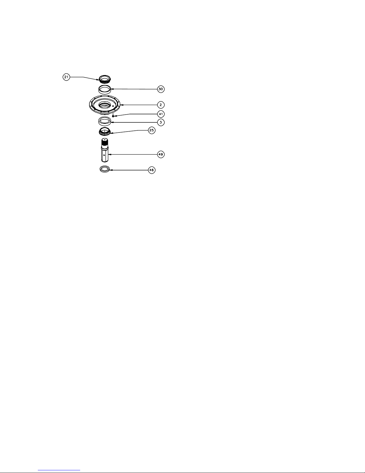
(ITEMS 2,3,21,25,30,46, & 49)
DISASSEMBLY AND REPAIR
CAUTION: Output shaft is no longer retained. Care
should be taken not to injure feet because output shaft can
fall out. Care should also be taken not to damage output
shaft when shaft is pressed through base.
1) Output shaft removal. Bearing carrier (2) should be set
pinion side down, as shown, on a plate or table with output
shaft (49) protruding through a hole in table. Press output
shaft out bottom of base by applying a load to top end
(internal end) of shaft until it passes through inner shaft
bearing cone (21).
BASE ASSEMBLY
NOTE: Press bearing cone onto output shaft by pressing
on inner race only. DO NOT press on roller cage or it may
damage bearing.
1) If outer bearing cone (25) was removed for replacement, press a new bearing cone (large end down as
shown) onto the shaft until it seats against the shoulder.
2) Place the bearing carrier (2) (output side up, opposite
shown) on the press table.
3) Apply a layer of lithium or general purpose bearing
grease to surface of outer bearing cup (3). Insert the shaft
(49) into the bearing carrier (2) (bearing cone down) and
use a soft hammer to install the shaft seal (46) into the
bearing carrer.
CAUTION: Output shaft is not retained at this point.
4) Invert this assembly so it is standing on the shaft (on the
press table).
NOTE: Press bearing cone onto output shaft by pressing
on inner race only. DO NOT press on roller cage or it may
damage bearing.
5) Apply a layer of lithium or general purpose bearing
grease to surface of inner bearing cup (30). Press the
inner bearing cone (21) (large end up as shown) onto the
shaft (49) until it is seated against inner bearing cup (30).
All subassembly service or repairs should be complete at
this time. Continue on through UNIT ASSEMBLY to
complete unit buildup.
NOTE: If reusing old bearing cone, do not damage roller
cage by pulling on it.
2) If outer bearing cone (25) needs to be replaced a gear
puller may be used.
3) Remove the shaft seal (46) for inspection or replacement. Lubricate inner lip of new shaft seal (46) and slide
the seal onto the shaft (49) until it fits snugly over shaft seal
diameter with the open side toward the inside of the auger
drive.
4) Inspect inner and outer bearing cups (30 & 3) and
replace if necessary.
4UNIT
 Loading...