

Page 1
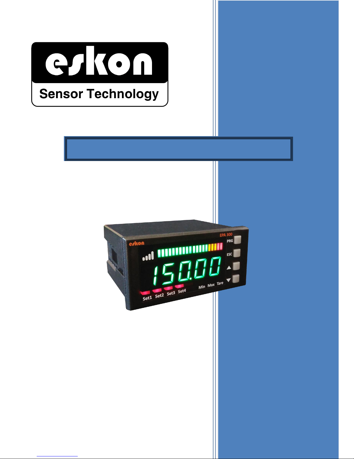
EPA300
CANopen
CANOPEN
USER
MANUAL
PROCESS CONTROL DEVICE
Page 2

2
INDEX
INDEX --------------------------------------------------------------------------------------------------------------------- 2
1. CONFIGURATION ------------------------------------------------------------------------------------------------ 3
2.1. Configuration with Layer Setting Service (LSS) --------------------------------------------------------------------------------- 3
2.2. Configuration with Service Data Objects (SDO) -------------------------------------------------------------------------------- 5
2. OBJECT DICTIONARY ------------------------------------------------------------------------------------------- 7
Page 3
3
1. CONFIGURATION
2.1. Configuration with Layer Setting Service (LSS)
Use the following tables to set the Node ID and bit rate using the LSS protocol.
* For the configuration with LSS, the bit rate settings of Master device and Slave device must be the
same.
* For configuration with LSS, only Master and Slave devices should be in the network.
* The default bit rate for your EPA300 device is 250 kbps and the Node ID is 1.
** To change any value with LSS, the device must be in Configuration Mode.
*** Please restart your device for changes to take effect.
LSS-Master Request COB-ID for LSS-Slave operations: 0x7E5
LSS-Slave Response COB-ID for LSS-Master operations: 0x7E4
To switch to the Configuration mode required to make Node ID or Baud Rate changes; If you do not want
all devices to use the Switch Mode Global command; Use Switch Mode Selective commands only if it is a
device on your network. For Selective mode, you need to know one of the Vendor ID, Product Code,
Revision Number, Serial Number or Node ID of your device. If you do not know, you can use the Inquire
commands by connecting your Master device and the Slave device you want to learn.
COB-ID
DATA (Hex)
COMMAND
EXPLANATION
0x7E5
04 00 00 00 00 00 00 00
Switch Mode Global -
Operation Mode
Command to import all connected devices
into Operational Mode
0x7E5
04 01 00 00 00 00 00 00
Switch Mode Global -
Configuration Mode
Command to import all connected devices
into Configuration Mode
0x7E5
5A 00 00 00 00 00 00 00
Inquire - Vendor ID
Vendor ID request command from sensor
0x7E4
5A ZZ 00 00 00 00 00 00
Vendor ID : 0xZZ
The answer from the sensor contains the
Vendor ID information.
0x7E5
5B 00 00 00 00 00 00 00
Inquire - Product Code
Command to request product code from
sensor
0x7E4
5B YY ZZ 00 00 00 00 00
Product Code : 0xZZYY
The answer from the sensor contains
Product Code information
0x7E5
5C 00 00 00 00 00 00 00
Inquire - Revision
Number
Request Revision Number from Sensor
0x7E4
5C XX YY ZZ 00 00 00 00
Revision Number :
0xZZYYXX
The response from the sensor contains
Revision Number information
0x7E5
5D 00 00 00 00 00 00 00
Inquire - Serial Number
Command to request Serial Number from
sensor
0x7E4
5D TT XX YY ZZ 00 00 00
Serial Number :
0xZZYYXXTT
The response from the sensor contains
Serial Number information.
0x7E5
5E 00 00 00 00 00 00 00
Inquire - Node ID
Command to request Node ID from sensor
0x7E4
5E ZY 00 00 00 00 00 00
Node ID – NID : 0xZY
The response from the sensor contains
Node ID information.
0x7E5
40 ZZ 00 00 00 00 00 00
Switch Mode Selective
– Vendor ID : 0xZZ
0xZZ Command to import Vendor ID device
into Configuration Mode
Page 4

4
0x7E5
41 YY ZZ 00 00 00 00 00
Switch Mode Selective
– Product Code :
0xZZYY
0xZZYY Command to import Product Code
Device into Configuration Mode
0x7E5
42 XX YY ZZ 00 00 00 00
Switch Mode Selective-
Revision Number:
0xZZYYXX
0xZZYYXX Command to import Revision
Number Device into Configuration Mode
0x7E5
43 TT XX YY ZZ 00 00 00
Switch Mode Selective
– Serial Nr. :
0xZZYYXXTT
0xZZYYXXTT Command to import Serial
Number Device into Configuration Mode
0x7E4
44 YY 00 00 00 00 00 00
Switch Mode Selective
Response
Response from sensor to switch to
Configuration Mode: 'YY'=00= Successful
'YY'=01= Unsuccessful
*** Please restart the device for changes to take effect.
You can use the following commands to make Node ID and Bitrate changes in your Slave device that you
have imported in Configuration mode. After the changes you have made, you must use the store
configuration command to save changes from the temporary memory to the permanent memory.
COB-ID
DATA (Hex)
COMMAND
EXPLANATION
0x7E5
13 XX 00 00 00 00 00 00
Configure Bit Rate
Sensor command for bit rate change
Values for [XX]: '00'=10 kbps, '01'=20 kbps,
'02'=50 kbps, '03'=100 kbps, '04'=125
kbps,
'05'=250 kbps, '06'=500 kbps,
'07'= 800 kbps, '08'= 1000 kpbs
0x7E4
13 YY 00 00 00 00 00 00
Configure Bit Rate
Response
Response from the sensor for bit rate
change: 'YY'=00= Successful
'YY'=01= Unsuccessful
0x7E5
11 XX 00 00 00 00 00 00
Configure Node ID
Sensor command for Node ID change:
for [XX]: Value between 1 and 127
0x7E4
11 YY 00 00 00 00 00 00
Configure Node ID
Response
Response from the sensor for Node ID
change: 'YY'=00= Successful 'YY'=01=
Unsuccessful
0x7E5
17 00 00 00 00 00 00 00
Store Configuration
Command to save changes
0x7E4
17 YY 00 00 00 00 00 00
Store Configuration
Response
The response to the command to save
changes: 'YY'=00= Successful 'YY'=01=
Unsuccessful
*** Please restart the device for changes to take effect.
Page 5

5
2.2. Configuration with Service Data Objects (SDO)
Use the following tables to set any parameters with the SDO protocol.
* For the configuration with SDO, the bit rate settings of Master device and Slave device should be
same.
* Node IDs of all CANopen devices in the network should be different from each other.
* The default bit rate for your EPA300 device is 250 kbps and the Node ID is 1.
** To change any value with SDO, the device must be in Configuration Mode.
*** Please restart your device for changes to take effect.
COB-ID
DATA (Hex)
COMMAND
EXPLANATION
0x600+Node
ID
22 ZZ YY XX TT SS RR PP
Download request
Write command
Index: 0xYYZZ Subindex: 0xXX
Data: 0xPPRRSSTT
0x580+Node
ID
60 ZZ YY XX 00 00 00 00
Download response
Confirmation that the parameter
successfully registered
0x600+Node
ID
11 ZZ YY XX 00 00 00 00
Upload request
Read command
Index: 0xYYZZ Subindex: 0xXX
0x580+Node
ID
11 ZZ YY XX TT SS RR PP
Upload response
Contains the information of the data
being read.
Index: 0xYYZZ Subindex: 0xXX
Data: 0xPPRRSSTT
0x580+Node
ID
80 ZZ YY XX TT SS RR PP
Abort message
response
If a command fails, it contains
information about what the error
means.
Index: 0xYYZZ Subindex: 0xXX
Hata kodu: [0xPPRRSSTT]
0x06090011: Subindex is incorrect
Error code: [0xPPRRSSTT] 0x06090030: Max value exceeded
list 0x06020000: Index is incorrect
0x06010001: Parameter writeonly
0x06010002: Parameter read-only
0x08000020: Data transfer error
0x08000000: General error
0x08000022: Incorrect state
*** Please restart the device for changes to take effect.
Example to make Node ID 2 of device with Node ID 1:
(NodeID): index=0x3001, subindex=0x00
COB-ID
DATA (Hex)
COMMAND
EXPLANATION
0x601
22 01 30 00 02 00 00 00
Download request
Write command
Data: 0x00000002
0x581
60 01 30 00 00 00 00 00
Download response
Node ID changed successfully
Node ID 2, Bit rate of 250 kbps device to make 125 kbps example:
(baudrate): index=0x3000, subindex=0x00
Page 6

6
COB-ID
DATA (Hex)
COMMAND
EXPLANATION
0x602
22 00 30 00 04 00 00 00
Download request
Write command / Data: 0x00000004
Options for the last two digits:
'00'=10 kbps, '01'=20 kbps, '02'=50 kbps,
'03'=100 kbps, '04'=125 kbps,
'05'=250 kbps, '06'=500 kbps,
'07'= 800 kbps, '08'= 1000 kpbs
0x582
60 00 30 00 00 00 00 00
Download response
Confirmation that the parameter
successfully registered
Page 7
7
2. OBJECT DICTIONARY
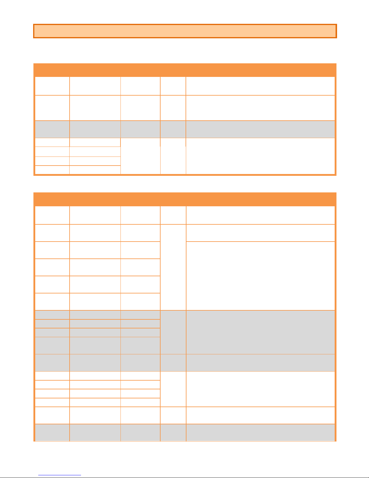
- All Index and Subindex are hexadecimal (0xZZZZ).
EPA300 CAN NETWORK SETTINGS
Index/
Subindex
Parameter
name
Data Type
Read/
Write
Explanation
3000
BaudRate
Unsigned 8
Read/
Write
CAN bit rate value, '0'=10 kbps, '1'=20 kbps
'2'=50 kbps, '3'=100 kbps, '4'=125 kbps, '5'=250
kbps '6'=500 kbps, '7'= 800 kbps '8'= 1000 kpbs
3001
NodeID
Unsigned 8
Read/
Write
NodeID value, between 1 and 127
3010/1
Unique_ID 1
Unsigned
32
Read/
Only
Device-specific Unique ID
3010/2
Unique_ID 2
3010/3
Unique_ID 3
3010/4
Unique_ID 4
OPERATING MODULE GENERAL FUNCTIONS
Index/
Subindex
Parameter
name
Data Type
Read/
Write
Explanation
2000/1
ProcessVal/
Raw16
Unsigned
16
Read/
Only
Unprocessed raw value from sensor
2000/2
ProcessVal/
Val16
Integer 16
Display value
2000/3
ProcessVal/
Val24
Integer 24
2000/4
ProcessVal/
Val32
Integer 32
2000/5
ProcessVal/
Real32
Real 32
2001/1
Valley/Val16
Integer 16
Read/
Only
The lowest value that appears since device was
turned on
2001/2
Valley/Val24
Integer 24
2001/3
Valley/Val32
Integer 32
2001/4
Valley/
ValReal32
Real 32
2001/5
Valley/Reset
Unsigned 8
Write/
Only
Enter '1' to reset the lowest value information
2002/1
Peak/Val16
Integer 16
Read/
Only
The highest value that has appeared since device
was turned on
2002/2
Peak/Val24
Integer 24
2002/3
Peak/Val32
Integer 32
2002/4
Peak/ValReal32
Real 32
2002/5
Peak/Reset
Unsigned 8
Write/
Only
Enter '1' to reset the maximum value
2003/1
TareFunc/
SignalStatus
Unsigned 8
Read/
Only
Status of external Tare Module
'0'=Devre Dışı '1'=Aktif
Page 8

8
2003/2
TareFunc/
TareStatus
Unsigned 8
Read-
Only
Status of internal Tare function
2003/3
TareFunc/
Apply
Write/
Only
Enter the '1' value to activate the internal Tare
function
2004/1
OutputFunc/
RelayOutputStatus
Unsigned 8
Read/
Only
Status of relay outputs
'0'= All relays disabled
Starting from the right, the relays are activated or
disabled so that each bit represents each relay in
turn.
Example: ’0101’= 1. ve 3. Relays active, 2. ve 4.
Relays passive
2004/2
OutputFunc/
RelayOutputSet
Write/
Only
Values for activating Relay Outputs:
'0000'= All relays disabled
‘0001’= 1. Relay active
‘0010’= 2. Relay active
‘0100’= 3. Relay active
‘1000’= 4. Relay active
2004/3
OutputFunc/
AnalogOutput1Stat
us
Real 32
Read/
Only
Percentage proportional if analog output module is
available
2004/4
OutputFunc/
AnalogOutput2Stat
us
Percentage proportional if analog output module is
available
2004/5
OutputFunc/
AnalogOutput3Stat
us
Percentage proportional if analog output module is
available
2004/6
OutputFunc/
AnalogOutput1Set
Write/
Only
Enter '1' to activate the analog output module if it
is available
2004/7
OutputFunc/
AnalogOutput2Set
Enter '1' to activate the analog output module if it
is available
2004/8
OutputFunc/
AnalogOutput2Set
Enter '1' to activate the analog output module if it
is available
2005/1
BuzzerFunc/
Play100ms
Unsigned 8
Write/
Only
When the '1' value is written, beep sounding buzzer
100 ms beat
2005/2
BuzzerFunc/Pla
y
Unsigned
16
When the '1' value is written, beep sounding buzzer
1 ms beat
2006/1
KeypadFunc/
KeypadStatus
Unsigned 8
Read/
Only
The state of the Up key
2006/2
KeypadFunc/
PressKeyN
Write/
Only
When '1' is written, the Up key is pressed and at
the same time the Tare function is activated.
2007
DioStatus
Unsigned 8
Write/
Only
For the first [3: 0] bit relay outputs, [4] bits indicate
the status for the external Tare module
0 = Inactive, 1 = Active
Page 9
9
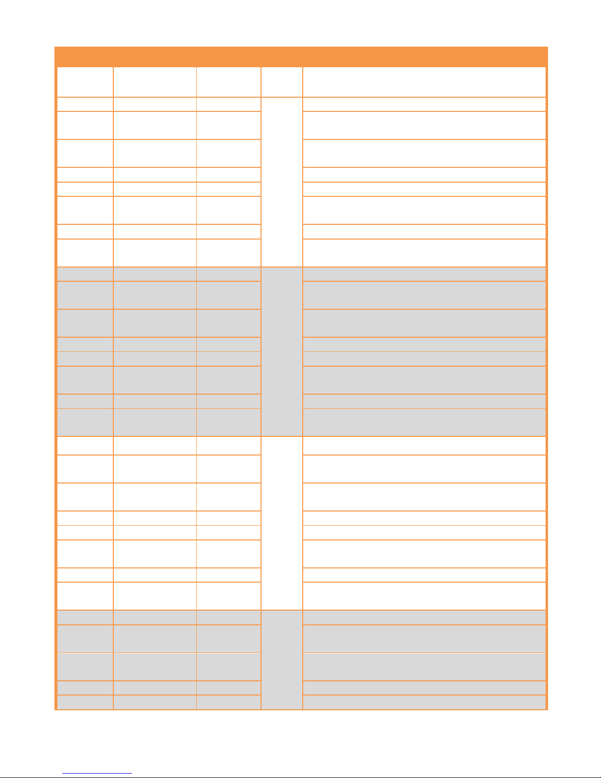
OUTPUT MENU
Index/
Subindex
Parameter
name
Data Type
Read/
Write
Explanation
2101/1
Out1 / Set 1A
Real 64
Read/
Write
Set 1A value for Relay 1
2101/2
Out1 / Set 1B
Real 64
Set 1B value according to type of function for
Relay 1
2101/3
Out1 / Mode
Unsigned 8
Function type for relay 1: '0'=OFF, '1'=Stand,
'2'=Band, '3'=Catch, '4'=Dual, '5'=Periodic
2101/4
Out1 / Delay
Real 64
Delay value for relay 1
2101/5
Out1 / HysUp
Real 64
Hysteresis UP value for relay 1
2101/6
Out1 /
HysDown
Real 64
Hysteresis DOWN value for relay 1
2101/7
Out1 / Offset
Real 64
Offset (start) value for the relay 1
2101/8
Out1 /
Condition
Unsigned 8
The normal state of the relay 1:
'0'=NC(Normally closed) '1'=NO(Normally open)
2102/1
Out2 / Set 2A
Real 64
Read/
Write
Set 2A value for Relay 2
2102/2
Out2 / Set 2B
Real 64
Set 2B value according to type of function for
Relay 2
2102/3
Out2 / Mode
Unsigned 8
Function type for relay 2: '0'=OFF, '1'=Stand,
'2'=Band, '3'=Catch, '4'=Dual, '5'=Periodic
2102/4
Out2 / Delay
Real 64
Delay value for relay 2
2102/5
Out2 / HysUp
Real 64
Hysteresis UP value for relay 2
2102/6
Out2 /
HysDown
Real 64
Hysteresis DOWN value for relay 2
2102/7
Out2 / Offset
Real 64
Offset (start) value for the relay 2
2102/8
Out2 /
Condition
Unsigned 8
The normal state of the relay 2:
'0'=NC(Normally closed) '1'=NO(Normally open)
2103/1
Out3 / Set 3A
Real 64
Read/
Write
Set 3A value for Relay 3
2103/2
Out3 / Set 3B
Real 64
Set 3B value according to type of function for
Relay 3
2103/3
Out3 / Mode
Unsigned 8
Function type for relay 3: '0'=OFF, '1'=Stand,
'2'=Band, '3'=Catch, '4'=Dual, '5'=Periodic
2103/4
Out3 / Delay
Real 64
Delay value for relay 3
2103/5
Out3 / HysUp
Real 64
Hysteresis UP value for relay 3
2103/6
Out3 /
HysDown
Real 64
Hysteresis DOWN value for relay 3
2103/7
Out3 / Offset
Real 64
Offset (start) value for the relay 3
2103/8
Out3 /
Condition
Unsigned 8
The normal state of the relay 3:
'0'=NC(Normally closed) '1'=NO(Normally open)
2104/1
Out4 / Set 4A
Real 64
Read/
Write
Set 4A value for Relay 4
2104/2
Out4 / Set 4B
Real 64
Set 4B value according to type of function for
Relay 4
2104/3
Out4 / Mode
Unsigned 8
Function type for relay 4: '0'=OFF, '1'=Stand,
'2'=Band, '3'=Catch, '4'=Dual, '5'=Periodic
2104/4
Out4 / Delay
Real 64
Delay value for relay 4
2104/5
Out4 / HysUp
Real 64
Hysteresis UP value for relay 4
Page 10
10
2104/6
Out4 /
HysDown
Real 64
Hysteresis DOWN value for relay 4
2104/7
Out4 / Offset
Real 64
Offset (start) value for the relay 4
2104/8
Out4 /
Condition
Unsigned 8
The normal state of the relay 4:
'0'=NC(Normally closed) '1'=NO(Normally open)
2106/1
CANopen/
BaudRate
Unsigned 8
Read/
Write
CAN bit rate value, '0'=10 kbps, '1'=20 kbps,
'2'=50 kbps, '3'=100 kbps, '4'=125 kbps, '5'=250
kbps '6'=500 kbps, '7'= 800 kbps '8'= 1000 kpbs
2106/2
CANopen/
NodeID
Unsigned 8
Read/
Write
NodeID value, between 1 and 127
2106/3
CANopen/
AutoOper
Your device connected to Master automatically
switches to Operational mode
'0' = Inactive, '1' = Active
2106/4
CANopen/
SendNmtOper
Automatically send Operational mode command to
CANopen which will be connected to it
'0' = Inactive, '1' = Active
2107/1
Rpdo1Setting/
CobID
Unsigned
32
Read/
Write
CobID value for RPDO1
2107/2
Rpdo1Setting/
DataStartBit
Unsigned 8
Start bit value for RPDO1
2107/3
Rpdo1Setting/
DataType
Data type for RPDO 1:
'0'=unsigned 16, '1'=unsigned 24,
'2'=unsigned 32,
'3'=int 16, '4'=int 24, '5'=int 32 '6'=real 32
2107/4
Rpdo1Setting/
MulFactor
Real 64
Product factor for RPDO1
2107/5
Rpdo1Setting/
CalibrationOpti
on
Unsigned 8
RPDO1 calibration on and off
'0' = Off, '1' = On
2108/1
Rpdo2Setting/
CobID
Unsigned
32
Read/
Write
CobID value for RPDO2
2108/2
Rpdo2Setting/
DataStartBit
Unsigned 8
Start bit value for RPDO2
2109/1
Tpdo1Setting/
MappedData
Unsigned 8
Read/
Write
Data type for TPDO1: '0'=unsigned 16, '1'=int 16,
'2'=int 24, '3'=int 32, '4'=real 32
2109/2
Tpdo1Setting/
EventTimer
Unsigned
16
TPDO data transmission time, in 'ms'
2120/1
UART/ Protocol
Unsigned 8
Read/
Write
Protocol selection for RS232 and RS485
connections '0'=ASCII, '1'=MB_RTU, '2'=MB_ASCII
2120/2
UART/ Adress
Unsigned 8
Address information for network connection
(Between 1 and 247)
2120/3
UART/ Baud
Unsigned 8
Baudrate option '0'=600, '1'=1200, '2'=2400,
'3'=4800, '4'=9600, '5'=14400, '6'=19200,
'7'=38400, '8'=57600, '9'=115200
2120/4
UART/ Parity
Unsigned 8
Parity option '0'=None, '1'=Odd, '2'=Even
2120/5
UART/ Period
Unsigned
16
For ASCII protocol Period (in 1/ms)
2130
Sound
Unsigned 8
Read/
Write
The state of beep sounding buzzer
'0' = Disabled, '1' = Active
Page 11
11
2140/1
AnalogOut1/
Type
Unsigned 8
Read/
Write
For analogue output module: '0'=0-10V, '1'=4-20
mA, '2'=0-5V, '3'=0.5-4.5V, '4'=0-20 mA
2140/2
AnalogOut1/
WaveForm
Unsigned 8
To select the analog output waveform ‘0’= linear,
‘1’=trian, ‘2’=sin, ‘3’=cos
2140/3
AnalogOut1/
Inverse
Unsigned 8
Read/
Write
Enable analogue outputs to increase or decrease in
reverse '0' = Inactive, '1' = Active
2140/4
AnalogOut1/
Scaling
Unsigned 8
Read/
Write
When you want to activate analog output
'0' = Inactive, '1' = Active
2140/5
AnalogOut1/
LowScale
Real 64
Minimum scale value when analogue output is 'on'
2140/6
AnalogOut1/
HighScale
Real 64
Maximum scale value when analogue output is 'on'
2140/7
AnalogOut1/
Condition
Unsigned 8
'0' = Inactive, '1' = Active
2141/1
AnalogOut2/
Type
Unsigned 8
Read/
Write
For analogue output module: '0'=0-10V, '1'=4-20
mA, '2'=0-5V, '3'=0.5-4.5V, '4'=0-20 mA
2141/2
AnalogOut2/
WaveForm
Unsigned 8
To select the analog output waveform ‘0’= linear,
‘1’=trian, ‘2’=sin, ‘3’=cos
2141/3
AnalogOut2/
Inverse
Unsigned 8
Enable analogue outputs to increase or decrease in
reverse '0' = Inactive, '1' = Active
2141/4
AnalogOut2/
Scaling
Unsigned 8
When you want to activate analog output
'0' = Inactive, '1' = Active
2141/5
AnalogOut2/
LowScale
Real 64
Minimum scale value when analogue output is 'on'
2141/6
AnalogOut2/
HighScale
Real 64
Maximum scale value when analogue output is 'on'
2141/7
AnalogOut2/
Condition
Unsigned 8
'0' = Inactive, '1' = Active
2142/1
AnalogOut3/
Type
Unsigned 8
Read/
Write
For analogue output module: '0'=0-10V, '1'=4-20
mA, '2'=0-5V, '3'=0.5-4.5V, '4'=0-20 mA
2142/2
AnalogOut/
WaveForm
Unsigned 8
To select the analog output waveform ‘0’= linear,
‘1’=trian, ‘2’=sin, ‘3’=cos
2142/3
AnalogOut3/
Inverse
Unsigned 8
Enable analogue outputs to increase or decrease in
reverse '0' = Inactive, '1' = Active
2142/4
AnalogOut3/
Scaling
Unsigned 8
When you want to activate analog output
'0' = Inactive, '1' = Active
2142/5
AnalogOut3/
LowScale
Real 64
Minimum scale value when analogue output is 'on'
2142/6
AnalogOut3/
HighScale
Real 64
Maximum scale value when analogue output is 'on'
2142/7
AnalogOut3/
Condition
Unsigned 8
'0' = Inactive, '1' = Active
Page 12
12
CALIBRATION MENU
Index/
Subinde
x
Parameter
name
Data Type
Read/
Write
Explanation
2201/1
Scale/Low
Real 64
Read/
Write
Minimal point for calibration S-LO value
2201/2
Scale/High
Maximum point for calibration S-HI value
2201/3
Scale/Factor
Scale factor for calibration
2202
CalibrationOptio
n
Unsigned 8
Read/
Write
Calibration option: '0' = FCAL: Factory calibration
'1' = 2_Pnt '2' = Segmented
2203/1
TwoPointCalib/
LowValue
Unsigned
16
Read/
Write
Value for minimum point in manual calibration
2203/2
TwoPointCalib/
HighValue
Value for maximum point in manual calibration
2203/3
TwoPointCalib/
CalLow
Unsigned 8
Write-
Only
Enter '1' to perform manual calibration
2203/4
TwoPointCalib/
CalHigh
Enter '1' to perform manual calibration
2204/1
SegmentedCalib/
Seg0_Value
Unsigned
16
Read/
Write
Value for each segment in multiple calibrations
2204/2
SegmentedCalib/
Seg1_Value
2204/3
SegmentedCalib/
Seg2_Value
2204/4
SegmentedCalib/
Seg3_Value
2204/5
SegmentedCalib/
Seg4_Value
2204/6
SegmentedCalib/
Seg5_Value
2204/7
SegmentedCalib/
Seg6_Value
2204/8
SegmentedCalib/
Seg7_Value
2204/9
SegmentedCalib/
Seg8_Value
2204/10
SegmentedCalib/
Seg9_Value
2204/11
SegmentedCalib/
NumberofSegment
Unsigned 8
Number of multiple calibration points, 2 to 9
2204/12
SegmentedCalib/
CalibrateSegN
Write/
Only
Enter '1' to start multiple calibrations
Page 13
13
DISPLAY MENÜSÜ
Index/
Subinde
x
Parameter
name
Data Type
Read/
Write
Explanation
2301/1
Tare/Event
Unsigned 8
Read/
Write
Tare event mode option
'0'=OFF, '1'=Zero, '2'=Preset,
'3'=Repeated Zero, '4'=Repeated Preset
2301/2
Tare/Preset
Real 64
Preset value for preset options
2301/3
Tare/InputEdge
Unsigned 8
Edge option that the signal will activate when the
button is pressed for the External Tare module
'0'=OFF '1'=Rise '2'=Fall
2301/4
Tare/Filter
Unsigned
16
The period for checking the incoming signal for the
External Tare module, in ms
2302
DecimalPoints
Unsigned 8
Read/
Write
The location of the point of the decimal digits
'0'=A, '1'=A.A, '2'=A.AA, '3'=A.AAA '4'=A.AAAA
2303
RefreshRate
Unsigned
16
Read/
Write
The rate of refresh on the screen in ms
2304/1
Filter/
AverageFilterOn
Unsigned 8
Read/
Write
Average filter to prevent flicker on the screen
'0'=OFF '1'=ON
2304/2
Filter/
AverageSampCount
Unsigned
16
Read/
Write
The number of reads to expect to calculate the
average filter
2304/3
Filter/LinearQuad
raticEstOn
Unsigned 8
LQE filter '0'=OFF '1'=ON
2304/4
Filter/Covariance
Unsigned
16
Covariance value for LQE filter
2304/5
Filter/Error
Unsigned
16
Error parameter for LQE filter
2304/6
Filter/Hysteresis
On
Unsigned 8
State option to enable or disable the hysteresis
filter '0' = inactive, '1' = active
2304/7
Filter/Delta
Unsigned
16
The value read on the display changes after the
entered delta value
2304/8
Filter/TotalError
Unsigned
16
When the sum of the non-reflected values on the
screen is equal to A.Error, the display is updated
with the average of these values
SECURE MENU
Index/
Subinde
x
Parameter
name
Data Type
Read/
Write
Explanation
2401/1
HideMenu/All
Unsigned 8
Read/
Write
Hide all menus except Secure
2401/2
HideMenu/Out
Hiding the output menu
2401/3
HideMenu/Calib
Hide the calibration menu
2401/4
HideMenu/
Display
Hide the display menu
Page 14

14
2401/5
HideMenu/
QuickOut
Hiding the entered quick set-up entry menu by
pressing and holding ESC in run mode
2402/1
LockMenu/All
Unsigned 8
Read/
Write
Encrypt all menus except Secure
2402/2
LockMenu/Out
Output menu encryption
2402/3
LockMenu/Calib
Calibration menu encryption
2402/4
LockMenu/
Display
Display menu encryption
2402/5
LockMenu/
QuickOut
Encrypt the entered quick set-up entry menu by
pressing and holding ESC in run mode
2403
UserPassword
Unsigned
32
Read/
Write
User password
2404
FactorySetting
Unsigned
32
Write-
Only
Enter '1' to return to the factory settings.
2405
DeviceReset
Unsigned 8
Read/
Write
Enter '1' to restart the device.
SERVICE MENU
Index/
Subinde
x
Parameter
name
Data Type
Read/
Write
Explanation
2506
ProductionDate
String
Read/
Only
Enter '1' to return to the factory settings.
2507
Assembler
String
Read/
Only
The sensor type of the device is '7' for CANopen
COMMUNICATION PARAMETRELERİ
Index/
Subinde
x
Parameter
name
Data Type
Read/
Write
Explanation
1000
Device type
Unsigned
32
Read-
only
Device type
1001
Error Register
Unsigned 8
Read-
only
1003/1
Standart Error
Field
Unsigned
32
Read-
only
Error history
1003/2
1003/3
1003/4
1003/5
1003/6
1003/7
1003/8
Page 15
15
1005
SYNC COB ID
Unsigned
32
Read/
Write
CAN-identifier. The default is 0x80.
1006
Communication
Cycle Period
Unsigned
32
Read/
Write
1008
Manufacturer
Device Name
String
Const.
Manufacturer-designated device name
1009
Manufacturer
Hardware
Version
String
Const.
Manufacturer's hardware version
100A
Manufacturer
Software Version
String
Const.
Device software version specified by manufacturer
1010/1
Save All
Parameters
Unsigned
32
Read/
Write
Each changed parameter is automatically saved, so
there is no need to change this parameter.
1011/1
Restore All
Default
Parameters
Unsigned
32
Read/
Write
To return to the default parameters, enter the
value 0x64616F6C.
1014
Emergency COB
ID
Unsigned
32
Read/
Write
Node ID + 0x80
1015
Inhibit Time
Emergency
Unsigned
16
Read/
Write
1017
Producer
Heartbeat Time
Unsigned
16
Read/
Write
Heartbeat value, in ms
1018/1
İdentity/Vendor
ID
Unsigned
32
Read-
only
Device-specific manufacturer-assigned numbers
1018/2
İdentity/Product
Code
1018/3
İdentity/Revision
Number
1018/4
İdentity/Serial
Number
SDO VE PDO PARAMETER
Index/
Subinde
x
Parameter
name
Data Type
Read/
Write
Explanation
0x1200: SERVER SDO
1200/1
COB ID Client to
Server
(Recieve SDO)
Unsigned
32
Read-
only
For sensor-to-device communication COB ID
Node ID + 0x600
1200/2
COB ID Server to
Client
(Transmit SDO)
For device-to-sensor communication COB ID
Node ID + 0x580
0x1400: Recieve PDO 1 Parameter
1400/1
COB ID
Unsigned
32
Read/
Write
COB ID for rPDO1 data from the network
Page 16
16
1400/2
Transmission
Type
Unsigned 8
These parameters are disabled.
1400/3
Inhibit Time
Unsigned
16
1400/5
Event Timer
Unsigned
16
1400/6
SYNC start value
Unsigned 8
0x1401: Recieve PDO 2 Parameter
1401/1
COB ID
Unsigned
32
Read/
Write
COB ID for rPDO2 data from the network
1401/2
Transmission
Type
Unsigned 8
These parameters are disabled.
1401/3
Inhibit Time
Unsigned
16
1401/5
Event Timer
Unsigned
16
1401/6
SYNC start value
Unsigned 8
0x1600: Recieve PDO Mappings: Static PDO mapping is used.
1600/1
Recieve PDO 1
Mapping*
Unsigned
32
Read/
Write
Mapping information for the value that appears on
the screen. COB ID (0x2107 / 1),
DataStartbit (0x2107 / 2), and
Datatype (0x2107 / 3) values must be specified.
1601/1
Recieve PDO 2
Mapping**
Unsigned
32
Read/
Write
Mapping information for analog output and digital
output. COB ID (0x2108 / 1),
DataStartbit (0x2108 / 2) must be specified.
0x1800: Transmit PDO 1 Parameter
1800/1
COB ID
Unsigned
32
Read/
Write
0x180
1800/2
Transmission
Type
Unsigned 8
0xFE(Manufacturer specific)
1800/3
Inhibit Time
Unsigned
16
0x00
1800/5
Event Timer
Unsigned
16
0x1F (500 ms)
1800/6
SYNC start value
Unsigned 8
0x00
0x1A00: Transmit PDO Mappings: Variable PDO mapping is used.
1A00/1
Transmit PDO 1
Mapping Process
Data Variable 1
Unsigned
32
Read/
Write
Default value: 0x20000520
(Object dictionary: 0x2000/1: Raw Data, Unsigned
16)
Mapping information for raw value from sensor
1A00/2
Transmit PDO 1
Mapping Process
Data Variable 2
Default value: 0x20070008
(Object dictionary: 0x2007: DioStatus, Unsigned 8)
Mapping information for the status of Digital
Outputs
Page 17

17
**8-bit data content table for 64-bit RPDO2: (Each tab refers to 8-bit data)
DATA 7
DATA 6
DATA 5
DATA 4
DATA 3
DATA 2
DATA 1
DATA 0
Analog Output value in percent of Real32 type
Input/Output
Durumu
 Loading...