

Page 1
1
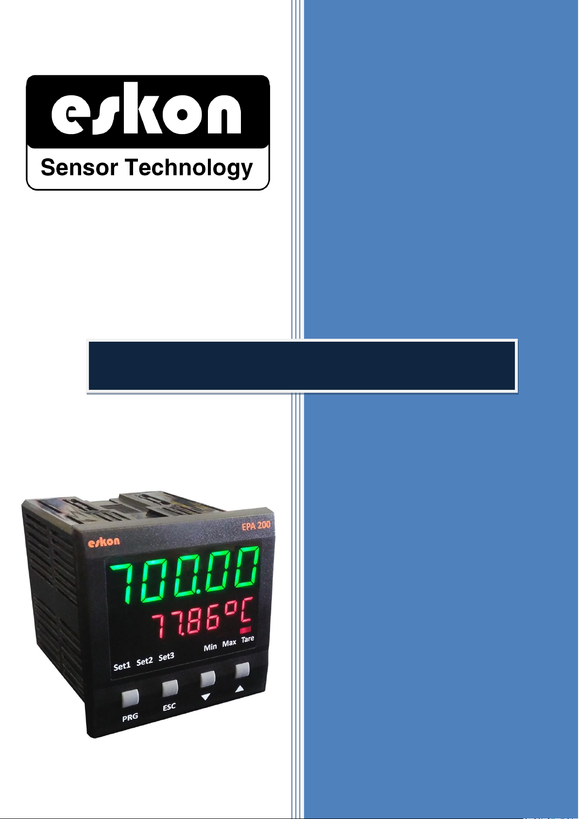
EPA 200
USER
PROCESS CONTROL DEVICE
MANUAL
KK-EPA.004 Rev No:0 28.09.18
Page 2

2
INDEX
INDEX ................................................................................................................................................................................ 2
1.TECHNICAL SPECIFICATIONS .......................................................................................................................................... 4
2. MECHANICAL DIMENSIONS .......................................................................................................................................... 4
3. CONNECTIONS ............................................................................................................................................................... 5
4. FRONT PANEL IDENTIFICATIONS ................................................................................................................................... 6
5. MENU TREE ................................................................................................................................................................... 7
6. SETUP ............................................................................................................................................................................ 8
6.1 Connecting the Sensor to the Device ...................................................................................................................... 8
6.2.1. Setting the Scale Value .................................................................................................................................. 9
6.2.2 Setting Factor Value ......................................................................................................................................... 9
6.2.3 Setting Calibration Method ............................................................................................................................ 10
6.2.4 Start Calibration (START) ................................................................................................................................ 11
6.3. ADJUSTING THE RELAY SET VALUES ..................................................................................................................... 11
6.3.1. Relay Output Settings ................................................................................................................................... 11
6.3.2 Changing Quick Set Values ............................................................................................................................. 12
6.4. RELAY PROGRAMMING MODE ............................................................................................................................ 12
6.4.1. Relay Function Selection ............................................................................................................................... 12
6.4.2 Delay .............................................................................................................................................................. 14
6.4.3. Hysteresis ...................................................................................................................................................... 14
6.4.4. Offset Value................................................................................................................................................... 15
6.4.5. Default Status Of The Relay (Cond) ............................................................................................................... 15
6.4.6. Sensor Selection (Snsor) ................................................................................................................................ 16
6.5. ANALOGUE OUTPUT SETTINGS ............................................................................................................................ 16
6.5.1. Analogue Output Type Selection .................................................................................................................. 16
6.5.2. Analogue Output ON/OFF ............................................................................................................................. 17
6.5.3. Inverse Setting .............................................................................................................................................. 17
6.5.4. Analogue Output Scale Setting ..................................................................................................................... 18
6.5.5. Wave Function .............................................................................................................................................. 18
6.6. DIGITAL OUTPUT SETTINGS .................................................................................................................................. 19
6.6.1. UART Settings ................................................................................................................................................ 19
6.6.2. CAN-Open Settings ........................................................................................................................................ 21
6.7. KEY TONE (SOUND) SETTING ................................................................................................................................ 25
6.8. SECURITY (SECURE) MENU ................................................................................................................................... 25
6.8.1. Hide the Menu (HIDE) ................................................................................................................................... 25
6.8.2. Lock the Menu (LOCK) ................................................................................................................................... 26
KK-EPA.004 Rev No:0 28.09.18
Page 3

3
6.8.3. Password Determination (PASS) ................................................................................................................... 26
6.8.4. Return to Factory Settings (FTRY) ................................................................................................................. 26
6.8.5. Restart the Device (RESET) ............................................................................................................................ 27
7. OTHER SETTINGS ......................................................................................................................................................... 27
7.1. Display Menu ....................................................................................................................................................... 27
7.1.1. Decimal Point (POINT) ................................................................................................................................... 27
7.1.2. Tare Function (TARE) ..................................................................................................................................... 28
7.1.2.1. Event .......................................................................................................................................................... 28
7.1.2.2. Input ........................................................................................................................................................... 28
7.1.3. Screen Refresh Rate (REFRS) ......................................................................................................................... 29
7.1.4. Prevention for Screen Flicker (FILTR) ........................................................................................................... 30
7.1.4.1. AVRGE (Average Calculation): .................................................................................................................... 30
8. OPERATION MODE FUNCTIONS .................................................................................................................................. 34
8.1. Tare (Reset ) Fonction ...................................................................................................................................... 34
8.2. Viewing Maximum and Minimum Values which are read ............................................................................... 34
9. PRODUCT CODING ...................................................................................................................................................... 35
10. WARRANTY CERTIFICATE .......................................................................................................................................... 36
KK-EPA.004 Rev No:0 28.09.18
Page 4
4
1.TECHNICAL SPECIFICATIONS
Supply Voltage
24 V
AC/DC
50/60 Hz
85-265 VAC 50/60 Hz
Power Consumption
9 VA / 2,7 Watt Maximum
Sensor Supply Voltage
Pot:
5 VDC
mV/V:
10 VDC
0-10V:
24 VDC
0-5V:
5 VDC
0,5-4,5V:
5 VDC
4-20 mA:
24 VDC
CANopen:
24 VDC
Max Sensor Supply Current
100 mA
Sampling Rate
3.5 kHz
Input Resolution
16 bit
Thermocouple Resolution
19 bit
RTD Resolution
15 bit
Analogue Inputs
Potentiometer, 0-10 V, 4-20 mA, 0-20 mA, 3,33 mV/V, 2mV/V, 2,5mV/V Ratiometric,
Thermocouple (K, J, N, R, S, T, E and B type), RTD
Relay Outputs
3 pcs 250 VAC 3A (For Resistive Load) Relay
Serial Communication (Optional)
RS-232, RS-485, USB, CANopen
Analogue Outputs (Optional)
0-10 V, 0-5 V, 0.5- 4.5 V, 4-20 mA, 0-20 mA
Analogue Output Resolution
12 bit
Connection
Terminals with 2,5 mm2 sockets
Operating Temperature
0 °C … 50 °C
Storage Temperature
-10 °C … 60 °C
Protection Class
IP60 Front Panel, IP20 Back Panel
Dimensions
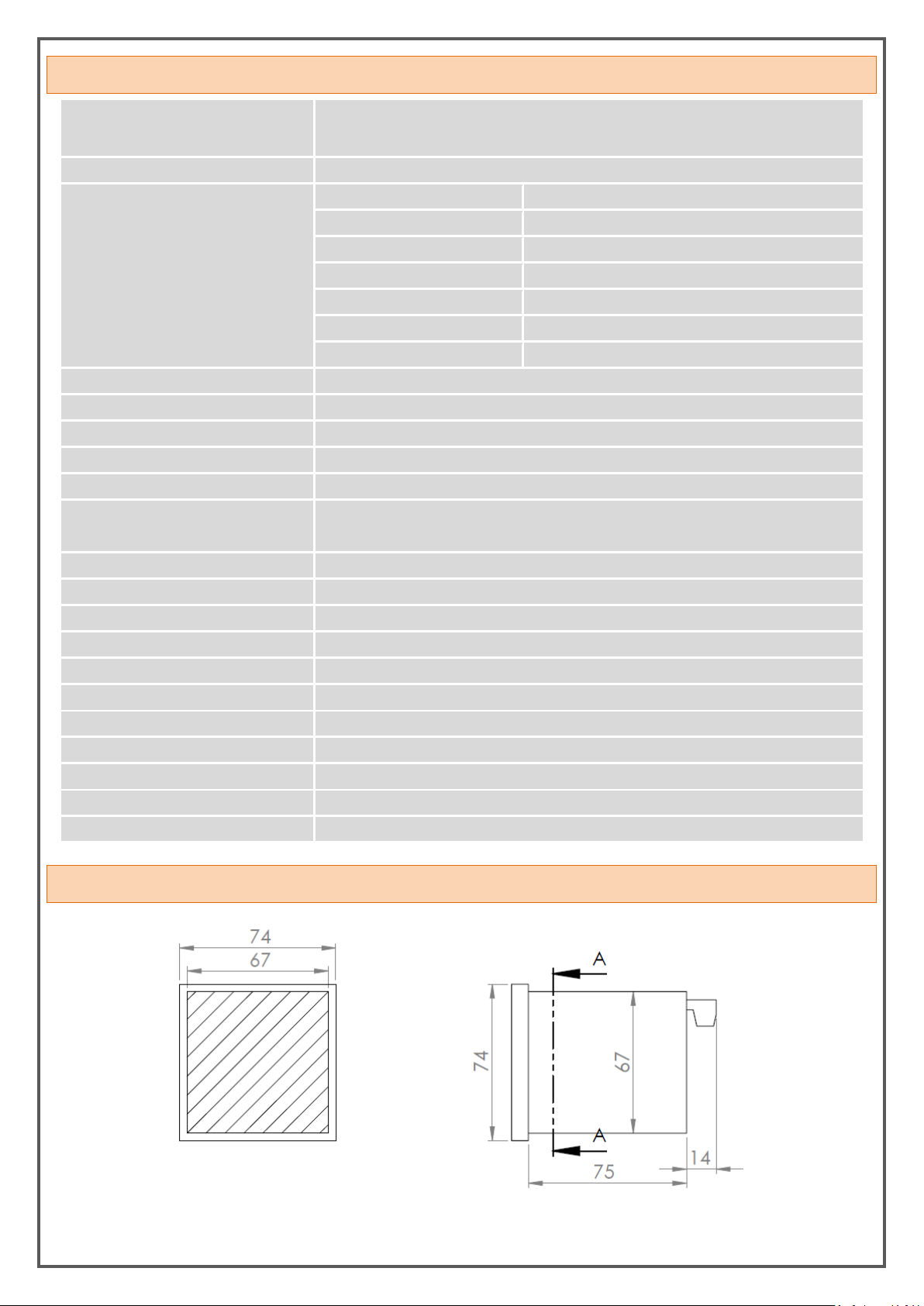
67 x 67 x 74 mm
Weight
~190 gr
Mounting
It is fixed to the panel with the feet at the top and bottom.
SECTION A-A
2. MECHANICAL DIMENSIONS
KK-EPA.004 Rev No:0 28.09.18
Page 5
5
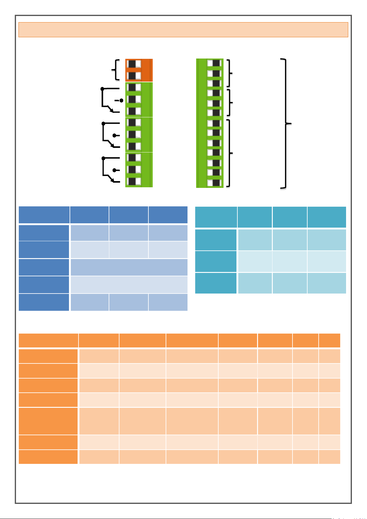
1. Relay Output
OUT-1
2. Relay Output
OUT-2
3. Relay Output
OUT-3
Supply Voltage
24 VAC/DC or
85/265 VAC
The following table
shows the pin
numbers.
Digital
Communication
Analogue Outputs
and Tare Input
Sensor Inputs
3. CONNECTIONS
Digital Conn.
12
13
14
RS485
A B GND
RS232
Rx
Tx
GND
USB HID
USB B TYPE CONNECTOR
USB VIRTUAL
USB B TYPE CONNECTOR
CANopen
CAN HIGH
CAN LOW
GND
Analogue
Outputs
15
16
17
4-20 mA
Output
GND
4-20 mA
Output
0-10 V
Output
GND
0-10 V
Output
Tare Input
Tare
Input
GND
1
2
3
4
5
6
7
8
9
10
11
24
23
22
21
20
19
18
17
16
15
14
13
12
SENSOR
24
23
22
21
20
19
18
Potentiometer
3. terminal
2. terminal
1. terminal
X X
4-20 mA Input
GND
Sensor Signal
Sensor Supply
X X
0-20 mA Input
GND
Sensor Signal
Sensor Supply
X X
0-10 V Input
GND
Sensor Signal
Sensor Supply
X X
3,33 mV/V Input
2 mV/V Input
2.5 mV/V Input
GND
X
Sensor Supply
Signal(-)
Signal(+)
Thermocouple
T-
T+
RTD
R-
R+
KK-EPA.004 Rev No:0 28.09.18
Page 6
6
SAFETY WARNINGS
1. Always follow the instructions and instructions in the operating instructions before making
the connections and during use.
2. Please check the power supply type before you connect energy to your device.
3. During the operation, be sure to mount it firmly on the panel to be used against falling,
sliding, shaking and shaking.
4. Make sure the sensor connections are not energized in your device, and do not disconnect or
connect the devices while the device is running.
5. Make sure that the cables between the sensor and your device are shielded and free from
high-current energy cables.
6. Do not expose your device directly to a heat source (solar, heater, etc.) in its operating
environment.
7. The EPA200 is an industrial control device which is not suitable for outdoor use; please use
only in room conditions.
8. Wipe with a damp cloth to clean your device, do not use water, alcohol, thinner and
similiar chemicals.
9. Comply with the limit values specified in the technical specifications for relay outputs.
10. The device cannot be changed by the user in the event of a fault, Please contact our
technical service in case of failure.
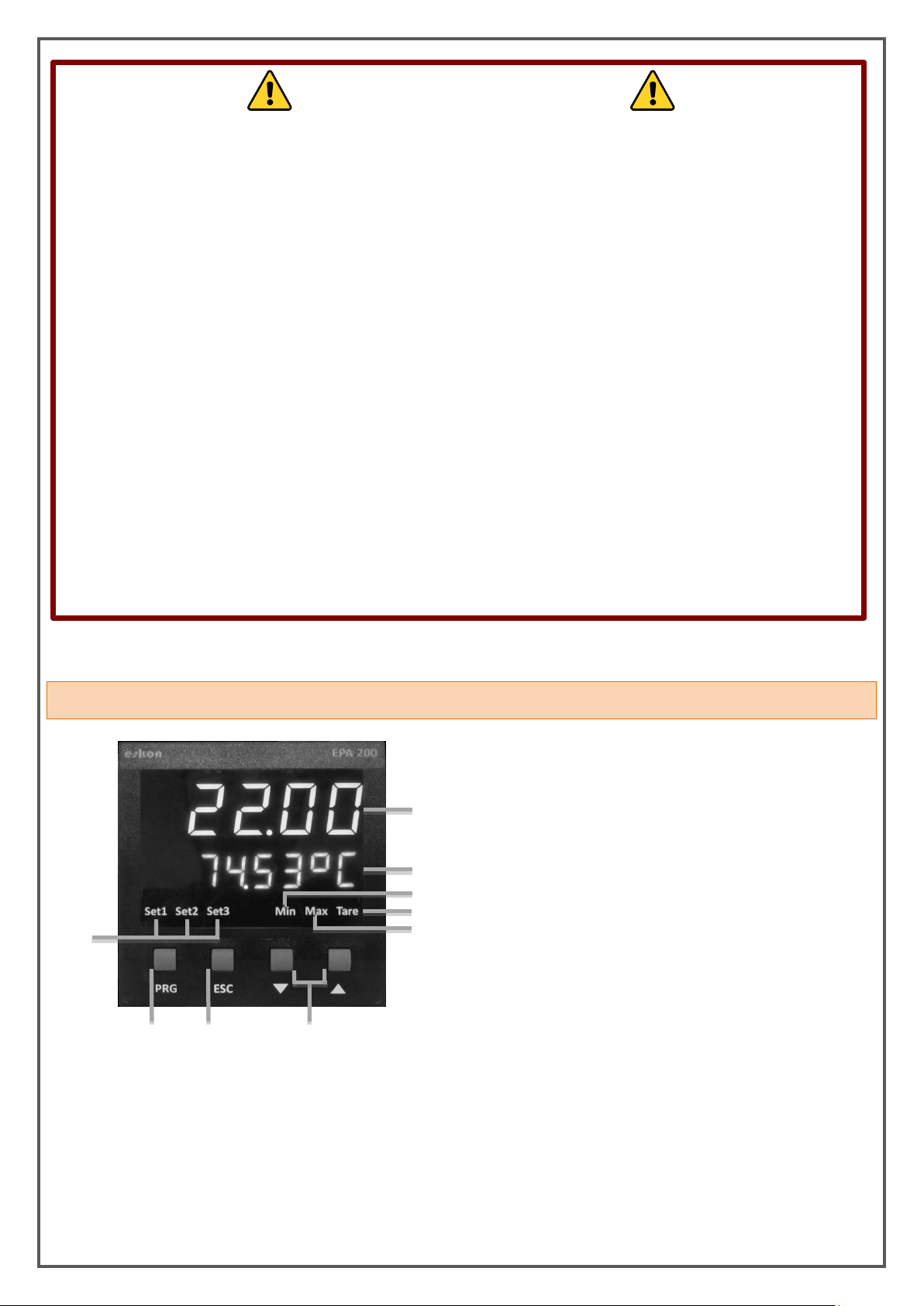
1) Top Display Line: It has 5 digits and shows the
measured process value.
2) Bottom Display Line: It has 6 digits and shows the relay
setpoint, the temperature measured by the thermocouple
or the ambient temperature.
3)Min Status LED: It lights up when the lowest
(minimum) value has been read since the moment the
device is started.
4) Max Status LED: It lights up when the maximum value
has been read since the moment the device is started.
5) Tare Status LED: It lights up when the Tare function is
active.
1
2
3 5 4
6
7 8 9
6) Set Status LEDs: The LED associated with the active relay lights up.
7) PRG Button: Programming and Enter key. It is used to enter menus or to confirm entered values.
8) ESC Button: Escape, exit and back key. It is used to return to the upper menu or to exit the menu.
9)UP and DOWN Buttons: Navigating through the menus; is used to increase and decrease the value while entering
values, or to move to a lower and higher digit.
4. FRONT PANEL IDENTIFICATIONS
KK-EPA.004 Rev No:0 28.09.18
Page 7
7
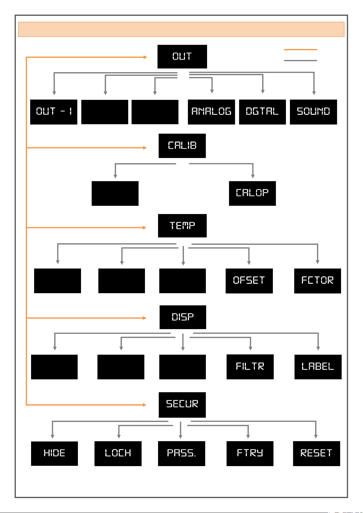
5. MENU TREE
Top Menu
Sub Menu
Out - 3
SCALE
LABEL
UNIT
POINT
POINT
TARE
REFRS
Out - 2
KK-EPA.004 Rev No:0 28.09.18
Page 8
8
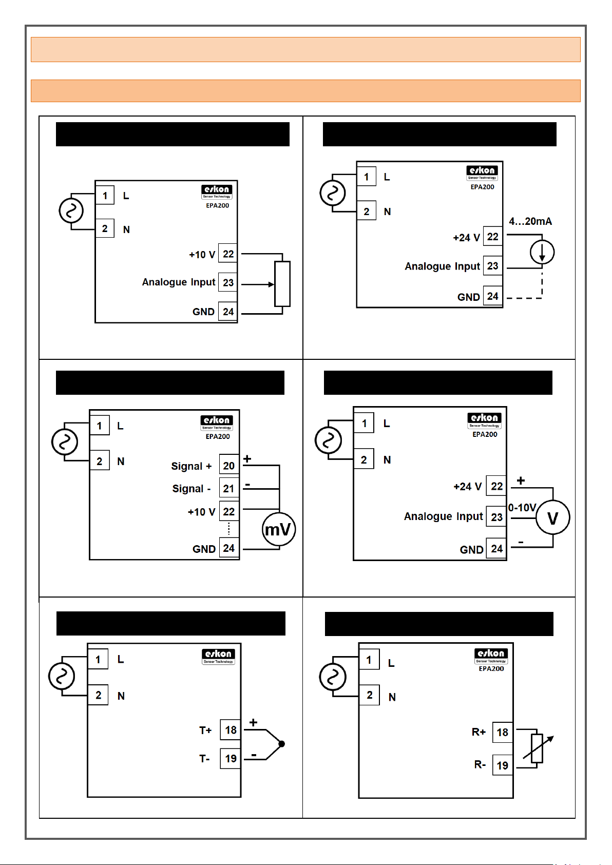
6. SETUP
4…20mA / 0…20mA Connection
*2 wire connection:
Sensor supply terminal must be connected to terminal 22
Sensor signal terminal must be connected to terminal 23
mV/Volt Connection
0…10 Volt Connection
Thermocouple Connection
RTD Connection
Potentiometer Connection
*0-5 V and 0.5-4.5 V connections are made as above.
*K, J, N, R, S, T, E and B type thermocouples can be connected
6.1 Connecting the Sensor to the Device
KK-EPA.004 Rev No:0 28.09.18
Page 9
9
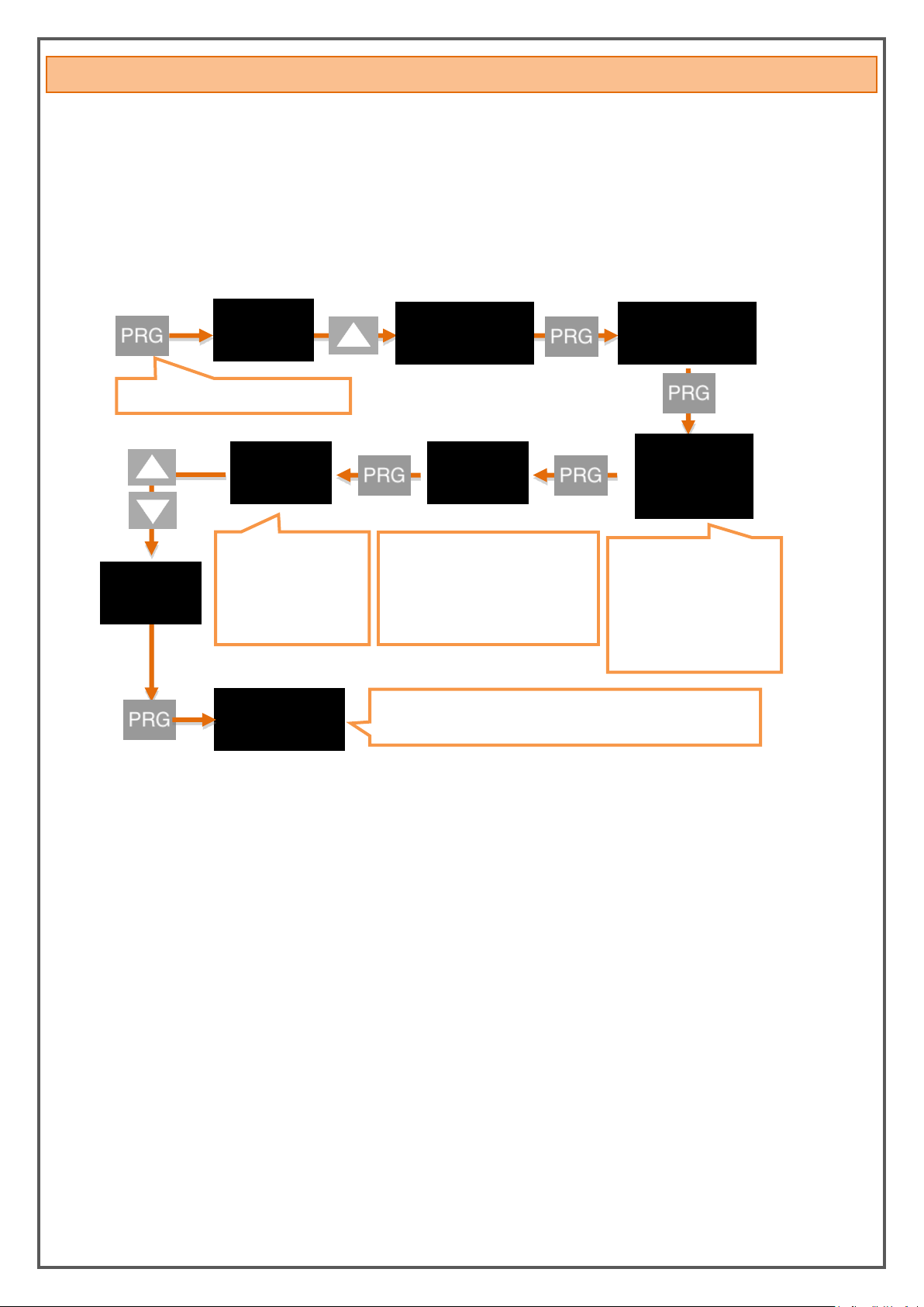
6.2 Device Calibration
25
25.
2.5
The decimal point
starts flashing. Use
the UP and DOWN
buttons to select the
decimal digits point.
Press and hold the UP button to
move to the next step. To enter a
negative (-) value, move to one of
the non-digit digits and press the
DOWN button.
When you press and hold
to the PRG key, the value
in the second line starts
blinking. Enter the
desired value using the
UP and DOWN buttons.
2.5
The new S-LO value you confirmed with the PRG key has been
set. Press UP button to move to S-HI.
OUT
S-LO.
0
Cal
I
b
SCALE
Press and hold the PRG button.
Press and hold to the PRG key to switch to the programming menu.
6.2.1. Setting the Scale Value
Your device is automatically calibrated to the factory settings and operates in the 0-100 range. That is, the
smallest value read on the sensor is 0, and the maximum value is 100 on the display. You can change this
scale on calibration menu. Use the S-LO for the minimum value displayed on the screen and the S-HI option
for the maximum value.
* After you have set the S-LO value, you can do the same for the S-HI value.
6.2.2 Setting Factor Value
You can use the Fctor menu to expand your scale by multiplying it with a fixed factor.The number of this
factor, which is the default value of 1, is multiplied by the values of S-LO and S-HI to determine the scale
value.
For example; When you set the S-LO value to 1, the S-HI value to 20 and make the factor 4, your device will
operate in the range of 4-80 value range.
WARNING: Changing the scale and factor value does not change the calibration of your device, it only
indicates the displayed value range on the screen.
KK-EPA.004 Rev No:0 28.09.18
Page 10

10
6.2.3 Setting Calibration Method
FCAL
2_Pnt.
SEGnt.
Factory calibration (Default)
CL.Cnt.
3
3
When the PRG button is pressed and entered into the menu, the second line starts blinking. Enter the desired value using
the UP and DOWN buttons and confirm by pressing the PRG button again.
START
CAL-L
XXX
.donE.
Multiple (Segmented )
Calibration
2 pointed calibration
CL.Cnt.
10
10
Your device has been calibrated during production. If you want, you can do this calibration according to
your sensor. To do that you should select the calibration method on this menu.
6.2.3.1 Factory calibration (default)
The default calibration on your device. The multipoint calibration or the two pointed calibration that you
have made to your device does not disturb the factory calibration.
6.2.3.2 Two-point calibration
By two-point calibration option, only the maximum and minimum points are selected. For example; While
you are calibrating a 10 cm linear potentiometer, the minimum point is identified when the potentiometer
is in the fully closed position and the maximum point is identified when the potentiometer is in the fully
open position.
* After you set the CAL-L value, you can do the same for the CAL-H value.
6.2.3.3 Multiple (segmented) Calibration
With the multiple calibration option, you can calibrate your device at up to 10 different points. This
method increases the linearity of the sensor.
For example; If the length of the sensor is 40 cm and you want to calibrate at 5 different points, these
points are; There may be 0. cm, 10. cm, 20 cm, 30 cm when sensor starts and 40 cm points where the
sensor ends. These points can be set anywhere in the scale range. We recommend you to choose by equal
intervals for a more suitable linearity.
6.2.3.4. Determining the Number of Calibrations (CL.CNT)
If you select the multi-segmented calibration option, in this menu that appears, you can specify the
number of points you want to calibrate the device. It's a maximum of 10.
KK-EPA.004 Rev No:0 28.09.18
Page 11

11
6.2.4 Start Calibration (START)
This error message can only be seen on devices with 4-20mA and 0.5-4.5V inputs.
Meaning; The sensor is not connected to the device or the sensor is defective.
OUT
25
30
30.
0.30
The decimal point
starts blinking. Use the
UP and DOWN buttons
to select the decimal
digit point.
Press and hold the UP button to move to the next
step.To enter a negative (-) value, move to one of
the non-digit digits and press the DOWN button.
When you press and
hold to the PRG key ,
the value in the
second line starts
blinking. Enter the
desired value using
the UP and DOWN
buttons.
The new SET-1 value you confirmed with the PRG button has
been set. You can return to run mode with the ESC button.
* You can also set other relay outputs in the same way.
START
SEG. 1
XXX
. . .
This process is
repeated for
each segment.
.DONE.
Press and hold the PRG button.
SET - 1
0.30
OUT - 1
SET - 1
25
Sn. err
After selecting the number of calibration, press the button to access the start menu.
Error Message:
6.3. ADJUSTING THE RELAY SET VALUES
Your device has tree relays in total with two contacts, normally open and normally closed. You can use the
relay contacts in five different functions according to your needs. These functions are described by 6.4.1
6.3.1. Relay Output Settings
Set the SET values in which the relay outputs of your device will be activated.
For SET 1 value;
KK-EPA.004 Rev No:0 28.09.18
Page 12
12
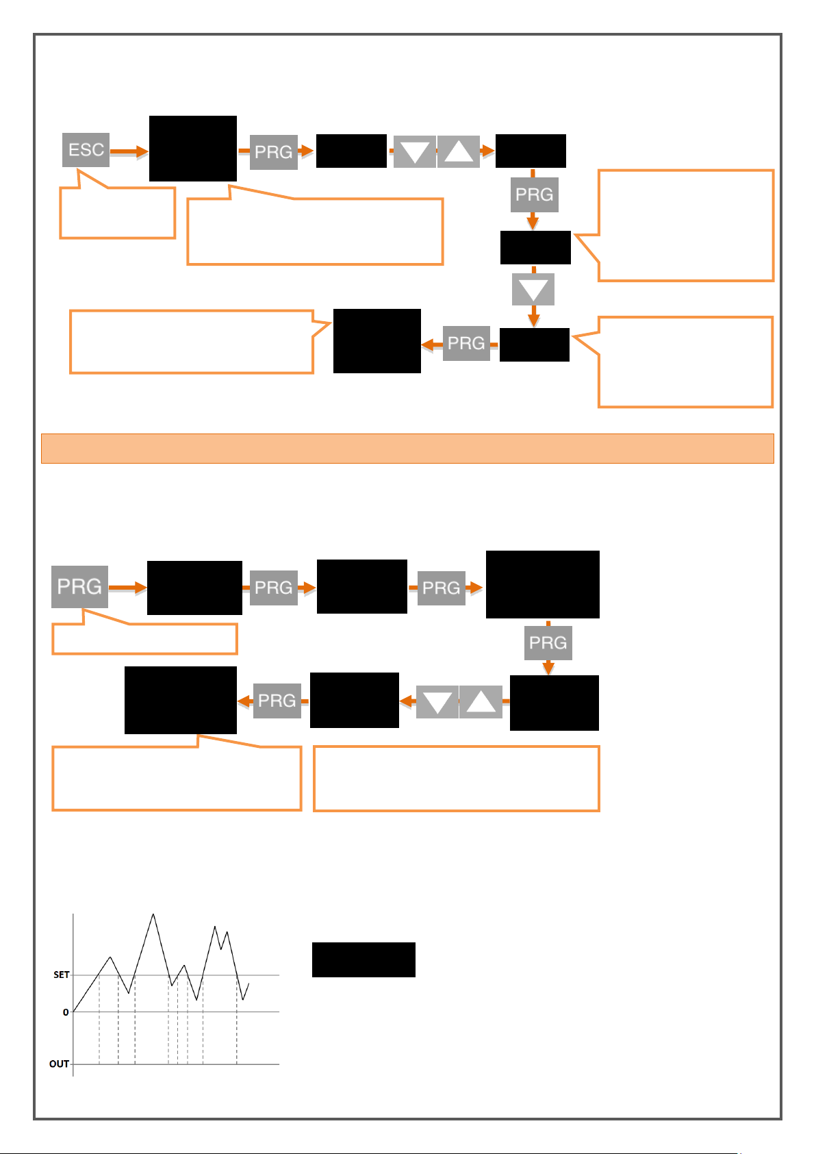
6.3.2 Changing Quick Set Values
* You can set the functions for other relay outputs in the same way.
SET - 1
0.25
25
Press and hold
the ESC button.
When you press and hold to the PRG key , the
value in the second line starts blinking. Enter
the desired value using the UP and DOWN
Press and hold the UP button
to move to the next step.To
enter a negative (-) value,
move to one of the non-digit
digits and press the DOWN
button.
The decimal digit point starts
blinking. Use the UP and
DOWN buttons to select the
decimal digit point.
25.
0.25
The new SET-1 value you confirmed with
the PRG button has been set. You can
return to run mode with the ESC button.
* You can set the quick set values for other relay outputs in the same way.
SET - 1
20
OFF
The relay does not switch off in any way.
20
Stand.
off
The new function you confirmed with the
PRG button has been set. You can return to
run mode with the ESC button.
Press and hold the PRG button.
Funct.
off
OUT - 1
OUT
Other function options can be changed by pressing
UP or DOWN buttons. Function options and
descriptions are shown below.
Funct.
Stand.
You can quickly change the adjustable relay set values when the device is in operation mode.
6.4. RELAY PROGRAMMING MODE
6.4.1. Relay Function Selection
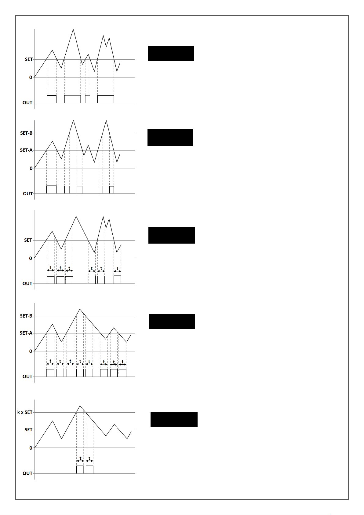
This function selection determines when the relay output will switch on and switch off according to the set
values.
Relay Function Options:
KK-EPA.004 Rev No:0 28.09.18
Page 13
13
STAND.
When the value read in the device reaches or exceeds Set-1,
the relay pulls.
BAND
When the value read on the device is between Set-1A and
Set-1B value, relay pulls.
CATCH
The value read on the device remains set to the value of Set-1
by increasing or decreasing the value of the relay each time it
is released for the time which is entered.
DUAL
When the value read in the instrument is increased or
decreased with the value of Set-1A or Set-1B, the relay remains
PER DC.
When the value read in the device is increased or decreases
with the value of Set-1 or the value of Set-1 in every floor
such as 2,3,4,5 ..., the relay remains drawn for the time
entered.
KK-EPA.004 Rev No:0 28.09.18
Page 14
14
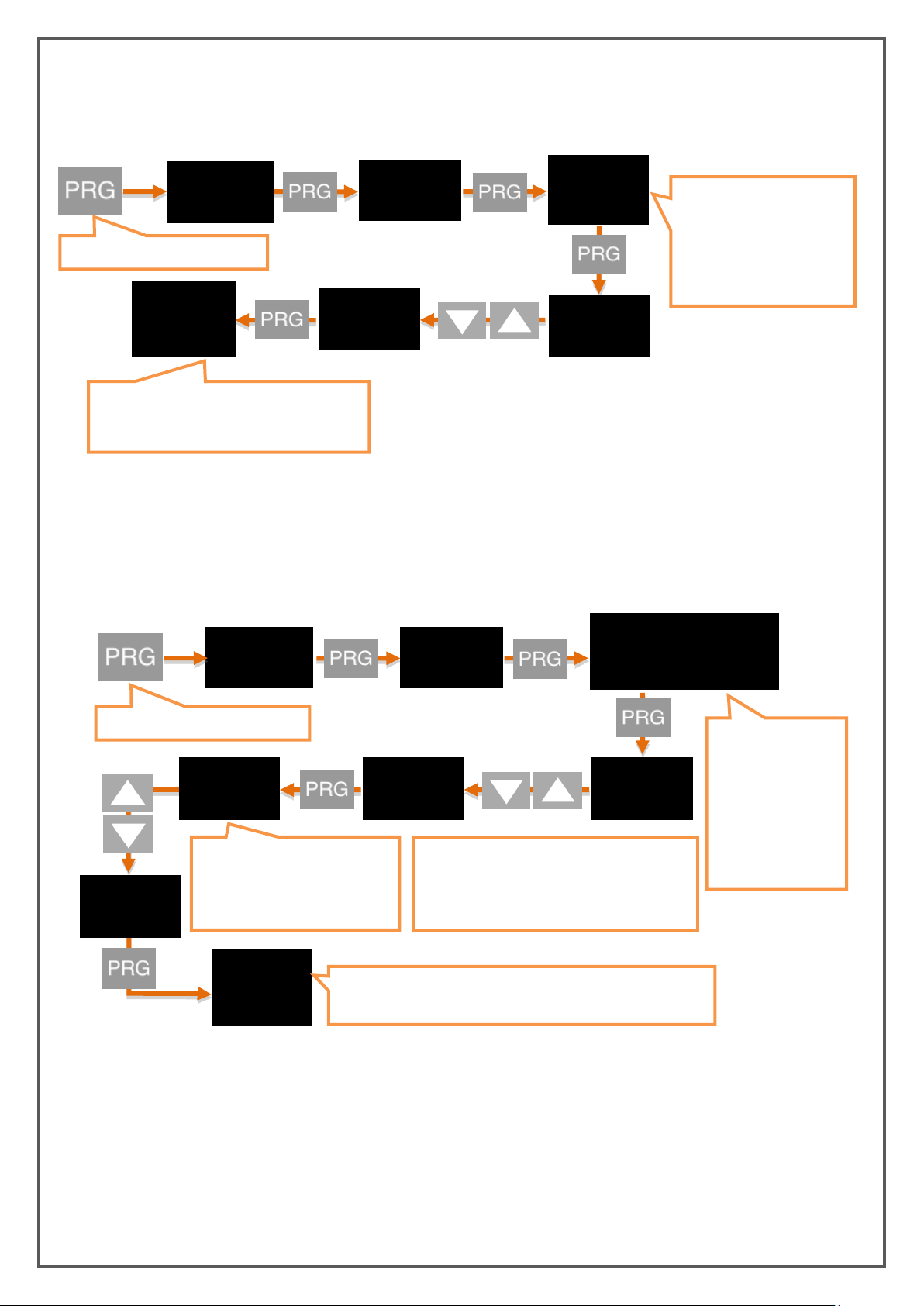
6.4.2 Delay
0
20
The new delay value you confirmed with the
PRG button has been set. You can return to
run mode with the ESC button.
Press and hold the PRG button.
delay
20
OUT - 1
OUT
delay
0
When you press and hold
to the PRG key , the value
in the second line starts
blinking. Enter the desired
value using the UP and
DOWN
OUT
0
30
30.
30
The decimal point starts
blinking. Use the UP and DOWN
buttons to select the decimal
digit point.
Press and hold the UP button to move to the
next step.To enter a negative (-) value, move
to one of the non-digit digits and press the
DOWN button.
When you press
and hold to the PRG
key , the value in
the second line
starts blinking.
Enter the desired
value using the UP
and DOWN
Press and hold the PRG button.
OUT - 1
Hysup/hysdn
0
hysup
30
The new hysteresis value you confirmed with the PRG button
has been set. You can return to run mode with the ESC button.
* You can also set other relay outputs in the same way.
* You can also set other relay outputs in the same way.
The relay specifies in seconds how long it will active and inactive after it is switched off. If '0' is entered as a
zero value in the Stand function, the relay will remain drawn unless the relay output condition changes.
6.4.3. Hysteresis
Due to the unstability in decimal value read on the connected sensor, you can enter the hysteresis value to
prevent the relay from being turned on and off at any time, so that the set value you set for the relay will
be activated and inactivated as low as Hysdn and above Hysup.
KK-EPA.004 Rev No:0 28.09.18
Page 15
15
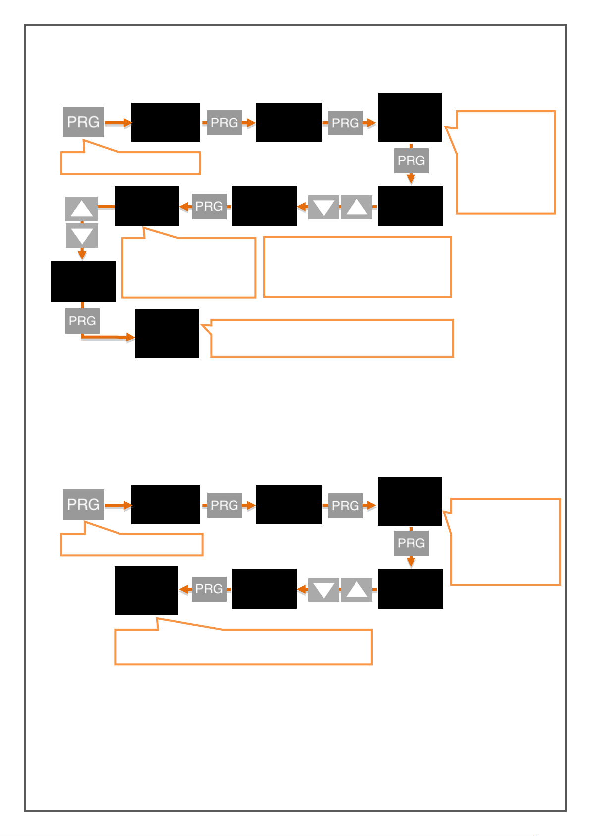
6.4.4. Offset Value
OUT
0
30
30.
30
The decimal point starts
flashing. Use the UP and DOWN
buttons to select the decimal
digit point.
Press and hold the UP button to move to the
next step.To enter a negative (-) value, move
to one of the non-digit digits and press the
DOWN button.
When you press and
hold to the PRG key ,
the value in the
second line starts
blinking. Enter the
desired value using
the UP and DOWN
* You can also set other relay outputs in the same way.
Press and hold the PRG button.
OUT - 1
OFSET
30
The new offset value you confirmed with the PRG button has
been set. You can return to run mode with the ESC button.
ofset
0
OUT
nc
no
When you press and hold
to the PRG key , the
value in the second line
starts blinking. Enter the
desired value using the
UP and DOWN
Press and hold the PRG button.
OUT - 1
cond
no
The new relay condition you confirmed with the PRG button has
been set. You can return to run mode with the ESC button.
cond
nc
* You can also set other relay outputs in the same way.
If you want to add offset to the entered set value, this menu is used. All set values are, as much as ofset
value is shifted forward and if it is selected negative then it is shifted backwards .
6.4.5. Default Status Of The Relay (Cond)
Depending on the factory settings of your device, the relay is normally off, so you can change it as normally
open. Use the Cond option to do this. The factory setting NC (Normally Closed) indicates that the relay is
normally closed, NO. (Normally Open) indicates that the relay is normally open.
KK-EPA.004 Rev No:0 28.09.18
Page 16
16
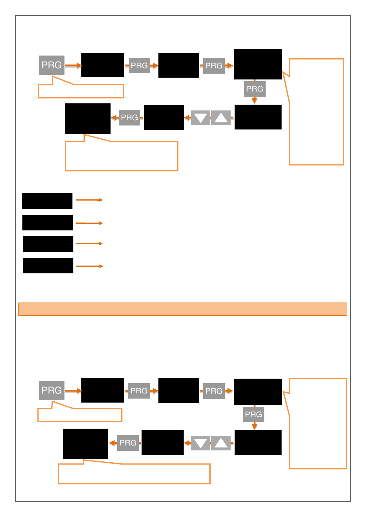
6.4.6. Sensor Selection (Snsor)
DEFAULT
When the relay output is wanted to be activated for sensor input, the
"DEFAULT" should be selected.
TEMP.
When the relay output is wanted to be activated for Thermocouple or RTD
input, the "TEMP" should be selected.
CAN.dt 1
When the relay output is wanted to be activated for CAN-Open
communucation connection through data-1, the "CAN.dt1" should be
CAN.dt 2
When the relay output is wanted to be activated for CAN_Open
communucation connection through data-2, the "CAN.dt2" should be
OUT
dfault
temp
When you press
and hold to the
PRG key , the value
in the second line
starts blinking.
Enter the desired
value using the UP
and DOWN
buttons. Sensor
types that can be
selected and
descriptions are
shown below.
Press and hold the PRG button.
OUT - 1
snsor
temp
The new sensor type you confirmed with the
PRG button has been set. You can return to
run mode with the ESC button.
snsor
dfault
* You can also set other relay outputs in the same way.
OUT
0-10V
4-20ma
When you press and
hold to the PRG key ,
the value in the
second line starts
blinking. Enter the
desired value using
the UP and DOWN
buttons. Output
types that can be
selected are shown
below.
Press and hold the PRG button.
anlog
type
4-20ma
The new output type you confirmed with the PRG button has
been set. You can return to run mode with the ESC button.
type
0-10V
Assignment can be done to the selected relay for the sensor types shown below.
Sensor Type:
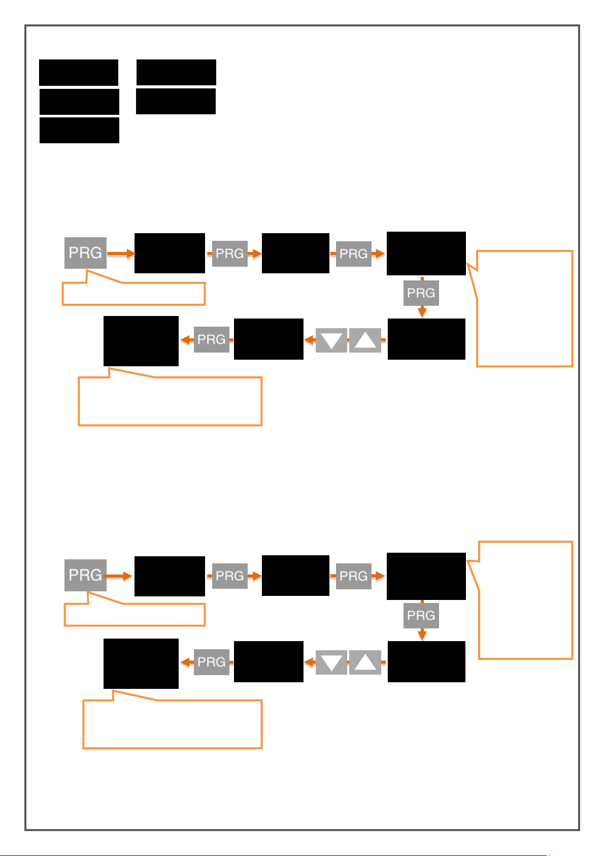
6.5. ANALOGUE OUTPUT SETTINGS
If your EPA 200, which is specially manufactured according to your order, has analogue output module, you
can make the necessary settings on this menu.
6.5.1. Analogue Output Type Selection
Under the Type menu, any of the following analogue output types can be selected.
KK-EPA.004 Rev No:0 28.09.18
Page 17
17
Analogue Output Types:
0-10V
4-20mA
0-5V
0.5-4.5V
0-20mA
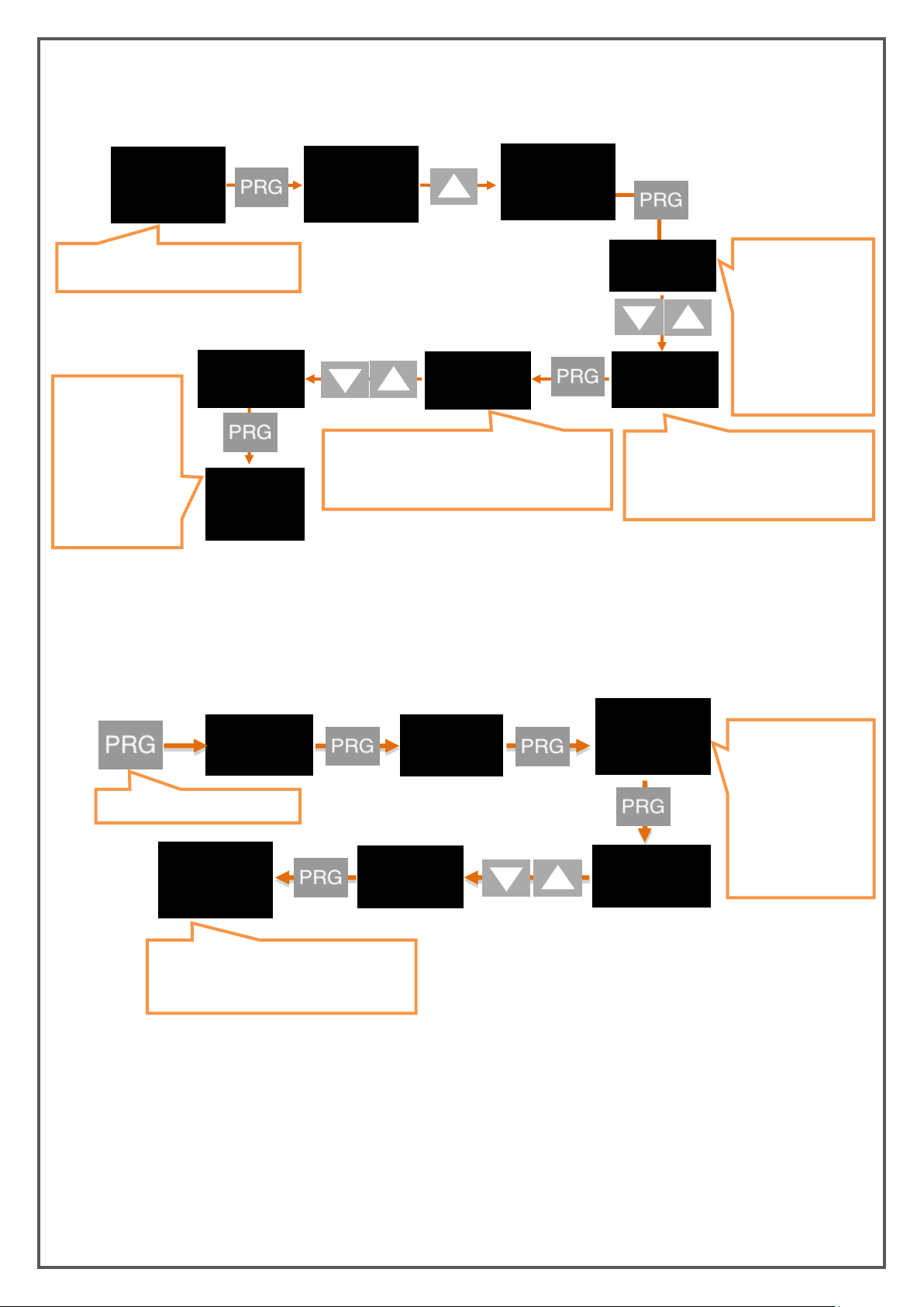
“ON” is used to turn on the analogue output and “OFF” is used to turn it off.
You can choose in which direction the value to be read on the analogue output increases or decreases
according to the sensor. This option, which is OFF according to the factory default settings, provides an
analogue output that increases or decreases in proportion to the value which is read at the sensor. If you
turn this ON, while the value which is read out at the sensor is increasing, the value at the analogue
output will decrease, ie an inversely proportional output will be provided.
OUT
on
off
When you press and
hold to the PRG key ,
the value in the
second line starts
blinking. Enter the
desired value using
the UP and DOWN
buttons.
Press and hold the PRG button.
anlog
cond
off
The new output condition you confirmed
with the PRG button has been set. You can
return to run mode with the ESC button.
cond
on
OUT
off
ON
When you press and
hold to the PRG key
the value in the
second line starts
blinking. You can
turn ON or OFF
using the DOWN
and UP buttons.
Press and hold the PRG button.
anlog
Invrs
oN
The new inverse condition you confirmed
with the PRG button has been set. You can
return to run mode with the ESC button.
Invrs
off
6.5.2. Analogue Output ON/OFF
6.5.3. Inverse Setting
KK-EPA.004 Rev No:0 28.09.18
Page 18
18
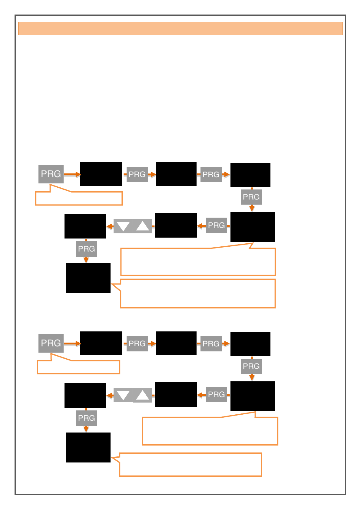
6.5.4. Analogue Output Scale Setting
Press the PRG button after selecting
ON with the direction buttons
When you press
and hold to the PRG
key the value in the
second line starts
blinking. Enter the
desired value using
the UP and DOWN
buttons.
Press and hold the UP button to move
to the next step.To enter a negative (-)
value, move to one of the non-digit
digits and press the DOWN button.
The decimal point starts flashing. Use the UP
and DOWN buttons to select the decimal digit
point.
S-LO.
0.20
The new S-LO
value you
confirmed with
the PRG button
has been set. You
can return to run
mode with the
ESC button.
* After you have set the S-LO value, you can do the same for the S-HI value.
SCALE
ON
SCALE
ON/OFF
S- LO.
0
20
20.
0.20
OUT
LINER
SIN.
When you press and
hold to the PRG key
the value in the
second line starts
blinking. Select the
desired wave form
using the UP and
DOWN buttons.
Press and hold the PRG button.
anlog
Vave.f.
SIN.
The new wave form you confirmed with
the PRG button has been set. You can
return to run mode with the ESC button.
Vave.f.
LINER
0
On the device with the analogue output feature, to set the output signal to the desired scale range, SCALE
mode on this menu must be ON. Then S-LO. and S-HI. values can be entered.
6.5.5. Wave Function
On this menu, you can find the linear standard waveform which is in the factory setting ; you can set as
the sine, cosine or triangular format.
KK-EPA.004 Rev No:0 28.09.18
Page 19
19
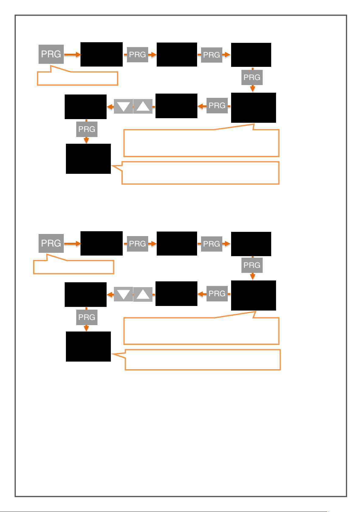
6.6. DIGITAL OUTPUT SETTINGS
OUT
ascII
When you press and hold to the PRG key the value in the second
line starts blinking. You can select one of ASCII, Modbus RTU
veya Modbus ASCII protocols using the UP and DOWN buttons.
Press and hold the PRG button.
dgtal
prtcl
MB.RTU
The new communucation protocol you confirmed with the PRG
button has been set. You can return to run mode with the ESC
button.
uart
prtcl
ascII
Mb.rtu
OUT
9600
When you press and hold to the PRG key the value in
the second line starts blinking. Select the desired
baudrate using the UP and DOWN buttons.
Press and hold the PRG button.
dgtal
baud
19200
The new baudrate you confirmed with the PRG button has
been set. You can return to run mode with the ESC button.
uart
baud
9600
19200
WARNING: After changing the UART or CANopen settings, you should restart the device to make the
changes to take effect.
If your device has a USB port, use MyPanelMeter, which you can download from our website to check your
device. Check the user manual of the program.
6.6.1. UART Settings
If you are communicating with your device via RS-485 or RS-232; You can make the necessary settings
here. You can select the communication protocol, baudrate, parity, address and period information. For
the MODBUS Protocol address information, see the relevant booklet.
6.6.1.1. Protocol Settings
6.6.1.2. Baudrate Setting
KK-EPA.004 Rev No:0 28.09.18
Page 20
20
6.6.1.3. Parity Setting
OUT
none
When you press and hold to the PRG key the value in the second
line starts blinking. You can select NONE, ODD or EVEN parity
using the UP and DOWN buttons.
Press and hold the PRG button.
dgtal
prITY
even
The new parity type you confirmed with the PRG button has been
set. You can return to run mode with the ESC button.
uart
prITY
none
even
OUT
1
When you press and hold to the PRG key the value in the second
line starts blinking. Enter the desired address value using the UP
and DOWN buttons.
dgtal
adres
2
The new address value you confirmed with the PRG button has
been set. You can return to run mode with the ESC button.
uart
adres
1
2
Press and hold the PRG button.
6.6.1.4. Address Setting
KK-EPA.004 Rev No:0 28.09.18
Page 21
21
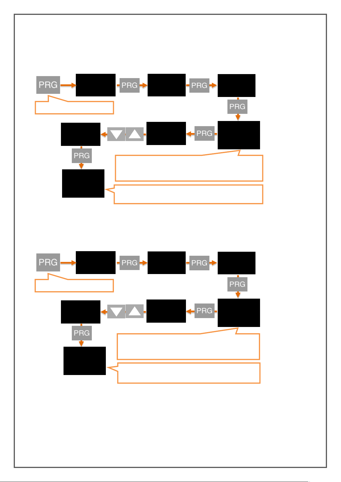
6.6.2. CAN-Open Settings
OUT
250
When you press and hold to the PRG key the value in the second
line starts blinking. Select the desired baudrate using the UP and
DOWN buttons.
Press and hold the PRG button.
dgtal
baud
500
The new baudrate you confirmed with the PRG button has been
set. You can return to run mode with the ESC button.
can
Baud
250
500
OUT
1
When you press and hold to the PRG key the value in the
second line starts blinking. Enter the desired NODE ID value
using the UP and DOWN buttons.
dgtal
baud
2
The new NODE ID you confirmed with the PRG button has been
set. You can return to run mode with the ESC button.
can
NOD.ID
1
2
Press and hold the PRG button.
Here you can set the baudrate, Node ID, Heartbeat, PDO etc. of your device related to CANopen protocol.
For more information on CANopen, see the EPA 200-CANopen booklet.
6.6.2.1. Baudrate Setting
6.6.2.2. NOD ID Setting
KK-EPA.004 Rev No:0 28.09.18
Page 22
22
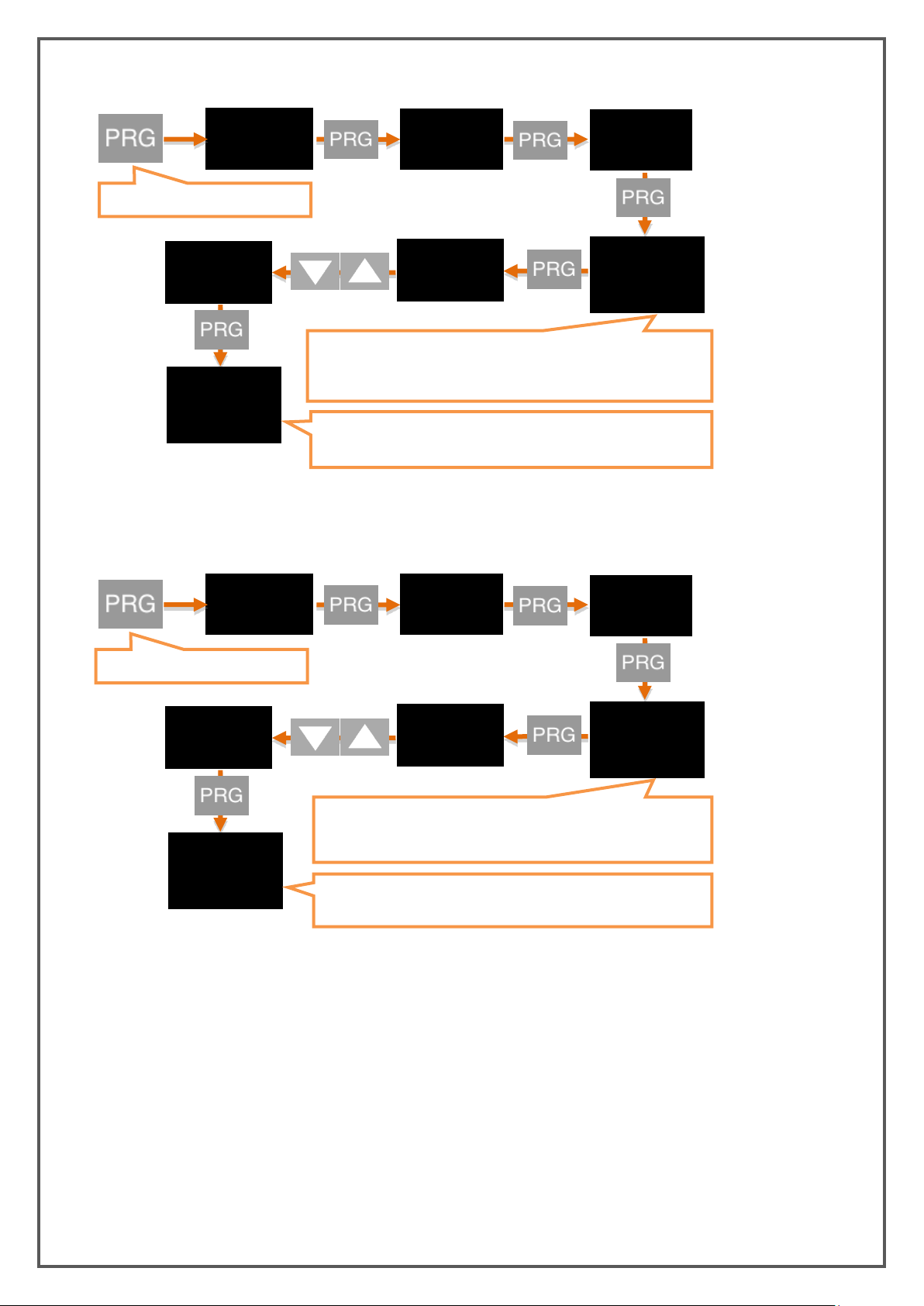
6.6.2.3. Heart Beat Setting
OUT
0
When you press and hold to the PRG key the value in the second
line starts blinking. Enter the desired Heart Beat value using the
UP and DOWN buttons.
dgtal
h.beat
2
The new Heart Beat value you confirmed with the PRG button has
been set. You can return to run mode with the ESC button.
can
h.beat
0
2
OUT
off
When you press and hold to the PRG key the value in the second
line starts blinking. You can turn ON or OFF using the DOWN and
UP buttons.
dgtal
Aut.op.
on
The new setting you confirmed with the PRG button has been
set. You can return to run mode with the ESC button.
can
Aut.op.
off
on
Press and hold the PRG button.
Press and hold the PRG button.
6.6.2.4. Auto Operation Setting
KK-EPA.004 Rev No:0 28.09.18
Page 23
23
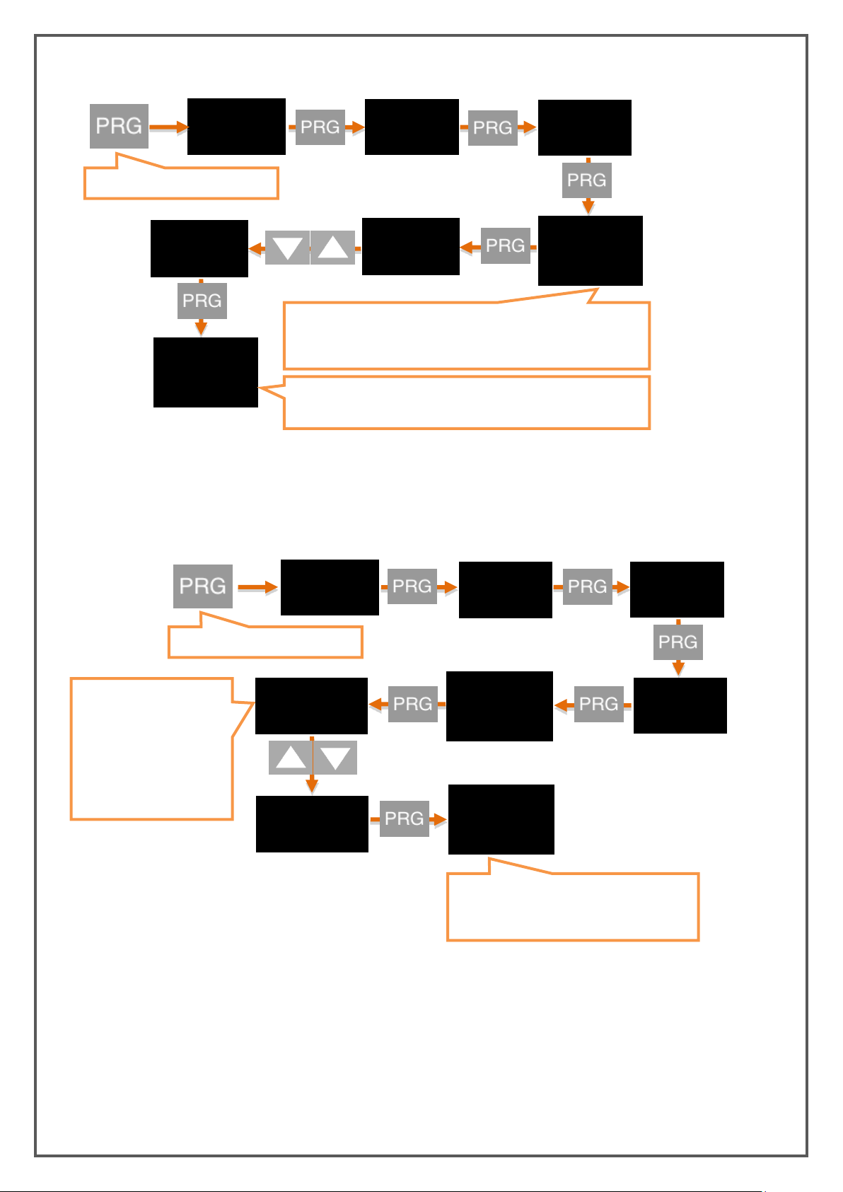
6.6.2.5. Send Operation Setting
OUT
255
When you press and hold to the PRG key the value in the second
line starts blinking. Enter the desired value using the UP and
DOWN buttons.
dgtal
Snd.op.
1
The new value you confirmed with the PRG button has been set.
You can return to run mode with the ESC button.
can
Snd.op.
255
1
OUT
When you press and hold
to the PRG key the value
in the second line starts
blinking. Select the
desired data type using
the UP and DOWN
buttons.
dgtal
The new data type you confirmed with the
PRG button has been set. You can return to
run mode with the ESC button.
can
TPDO 1
D.TYPE
REAL 32
REAL 32
INT 16
D.TYPE
INT 16
Press and hold the PRG button.
Press and hold the PRG button.
6.6.2.6. TPDO Setting
KK-EPA.004 Rev No:0 28.09.18
Page 24
24
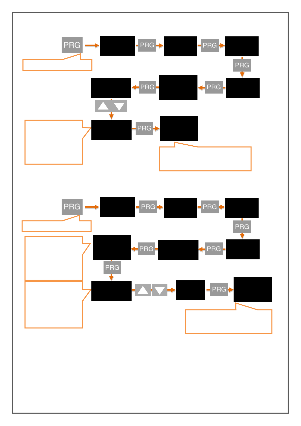
6.6.2.7. RPDO Setting
OUT
When you press and hold
to the PRG key the value
in the second line starts
blinking. Enter the desired
value using the UP and
DOWN buttons.
dgtal
The new ID value you confirmed with the
PRG button has been set. You can return to
run mode with the ESC button.
can
RPDO 1
COB ID
32
32
50
COB ID
50
OUT
When you press and hold
to the PRG key the value
in the second line starts
blinking. Enter the
desired value using the UP
and DOWN buttons.
dgtal
The new setting you confirmed with the
PRG button has been set. You can return
to run mode with the ESC button.
can
RPDO 1
0
DATA 1
BIT-1
0
From this area; BIT-1,
Data Type, Factor and
calibration ON / OFF
settings are made
separately. The example
is set to BIT-1.
1
BIT-1
1
* You can also do data-2 settings in the same way.
Press and hold the PRG button.
Press and hold the PRG button.
KK-EPA.004 Rev No:0 28.09.18
Page 25
25
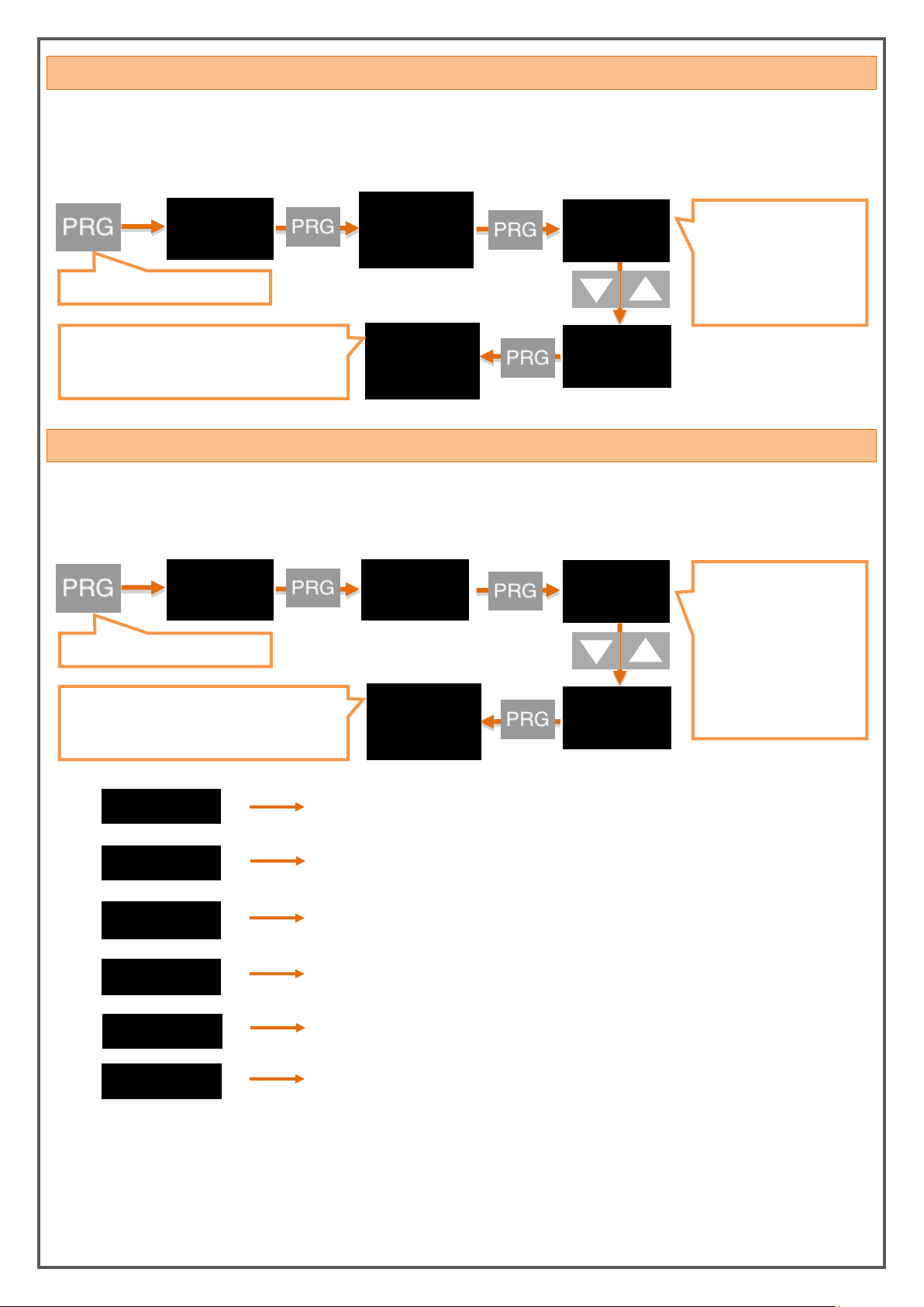
6.7. KEY TONE (SOUND) SETTING
HD.ALL
HD.OUT
HD.TMP
HD.DSP
All menus are hidden except Secure.
The Output menu is hidden.
The Calib menu is hidden.
The Temperature menu is hidden.
The display menu is hidden.
The Quick Set change menu is hidden.
HD.CLB
HD.FOU.
OUT
ON
When you press and hold
to the PRG key the value
in the second line starts
blinking. You can turn ON
or OFF using the DOWN
and UP buttons.
SOUND
oN
The new sound status you confirmed with the
PRG button has been set. You can return to
run mode with the ESC button.
SOUND
OFF
OFF
SECUR
ON
When the PRG button is
pressed and entered, the
hide options screen
appears. The desired type
of hide can be selected
using the UP and DOWN
buttons. The hiding
options and descriptions
are listed below.
HD.ALL
oN
The new hiding status you confirmed with the
PRG button has been set. You can return to
run mode with the ESC button.
HD.ALL
HIDE
Press and hold the PRG button.
Press and hold the PRG button.
When you press any key on your device, you can turn the beep sound on and off on this menu. Use ON to
turn on the sound, OFF to turn it off.
6.8. SECURITY (SECURE) MENU
6.8.1. Hide the Menu (HIDE)
By this menu, you can hide the menus that you don't want the operators see.
KK-EPA.004 Rev No:0 28.09.18
Page 26
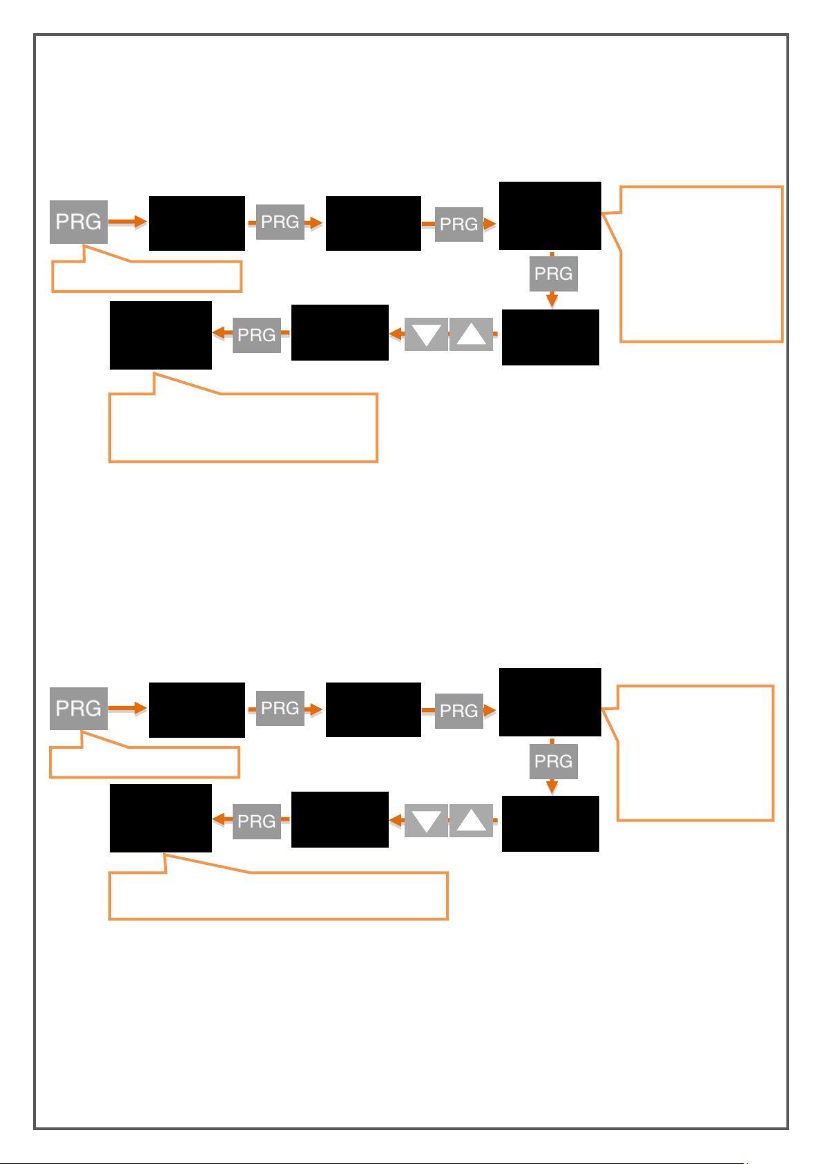
26
6.8.2. Lock the Menu (LOCK)
SECUR
off
When you press and hold
to the PRG key the value in
the second line starts
blinking. Use the UP and
DOWN buttons to get the
menu to the ON position.
The menus can all be
locked at the same time or
separately.
LOCK
on
Lc.all
0ff
Lc.all
on
The new setting you confirmed with the PRG
button has been set. You can return to run
mode with the ESC button.
SECUR
0
When you press and hold
to the PRG key the value
in the second line starts
blinking. Enter the
desired password using
the UP and DOWN
buttons.
PASS
12345
n.pass.
12345
n.pass.
0
The new password you confirmed with the PRG button has
been set. You can return to run mode with the ESC button.
Press and hold the PRG button.
Press and hold the PRG button.
If you have not set a password before, you will see NPASS in the display when you enter this menu. Press
the PRG key to set the desired password here. Then use the DOWN and UP keys to select ON the menus
you want to lock.
6.8.3. Password Determination (PASS)
Use this menu item to set a password or to change the password you have previously set. If no password
was previously set; When you enter this menu, the display will show NPASS. Press the PRG key to set the
desired password here. If the password has already been set; on the display PASS? will appear and you will
be asked to enter this password. After inputting the password, the display will show NPASS. You can
specify your new password here and confirm it by the PRG key.
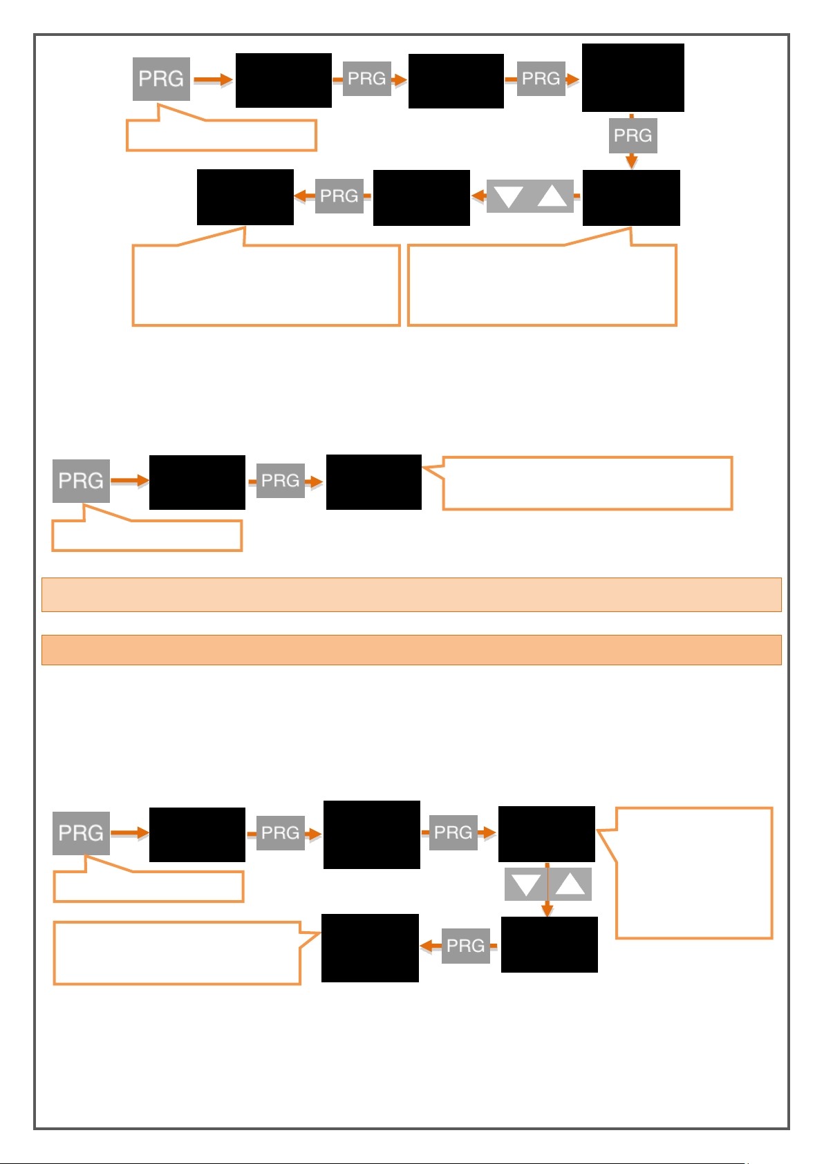
6.8.4. Return to Factory Settings (FTRY)
You can return the EPA 200 to its factory settings at any time. Press PRG key to come to this menu to
return to the factory settings. Here you are going to face the PASS? You need to enter 12345, which is the
factory password, not the user password you specified on the password screen.
KK-EPA.004 Rev No:0 28.09.18
Page 27
27
SECUR
0
When you press and hold to the PRG key the
value in the second line starts blinking. Enter
the factory password 12345 using the UP and
DOWN buttons.
FTRY
12345
After confirming the password with the PRG
button, a menu appears asking you if you are
sure. If you confirm with the PRG key, the
device returns to the factory settings.
PASSP
0
SURE.P
SECUR
The device will restart automatically after pressing
the PRG button.
reset
DISP
The new value you confirmed with the PRG
button has been set. You can return to run
mode with the ESC button.
POINT
2
2
When you press and hold
to the PRG key the value
in the second line starts
blinking. Enter the
desired value using the
UP and DOWN buttons.
3
POINT
3
Press and hold the PRG button.
Press and hold the PRG button.
Press and hold the PRG button.
6.8.5. Restart the Device (RESET)
In any case, press the PRG key to come back to this menu to restart your device. The device will
automatically power off and on and start working.
7. OTHER SETTINGS
7.1. Display Menu
7.1.1. Decimal Point (POINT)
In the value that appears on the display in run mode, you can set the position of the decimal point in this
menu. This value, which is '2' in the factory settings, indicates how many digits are displayed after the
currancy. If you select '0', only the integer appears on the screen.
KK-EPA.004 Rev No:0 28.09.18
Page 28
28
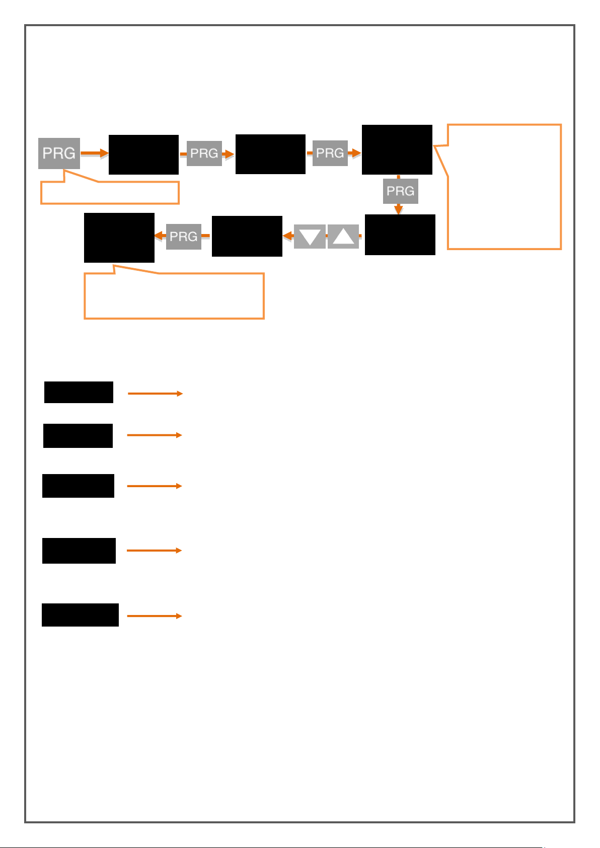
7.1.2. Tare Function (TARE)
zero
ZERO: Then the value which is read on the
sensor is made equal to zero and the Tare
status led lights on.
preset
PRESET: Then the value which is read on the sensor
is made equal to the set value and the Tare status
led lights on.
r. zero
REPEATED ZERO: When the first time it is pressed, the value which is
read on the sensor is made equal to zero and the Tare status led lights
on. When it is pressed next, the read value returns to the state before
the key is activated, and the Tare status led lights off.
r. prst
REPEATED PRESET: When the first time it is pressed, the value
which is read on the sensor is made equal and the Tare status led
lights on. When it is pressed next, the read value returns to the
state before the key is activated, and the Tare status led lights off.
off
Tare function is completely disabled and the Tare status led lights
off.
DISP
The new function you confirmed with the
PRG button has been set. You can return to
run mode with the ESC button.
When you press and hold
to the PRG key the value
in the second line starts
blinking. The desired
function can be selected
by using DOWN and UP
buttons. The functions
and descriptions that can
be selected are shown
below.
off
event
zero
TARE
EVENT
OFF
zero
Press and hold the PRG button.
In this menu you can specify different Tare functions.
7.1.2.1. Event
On the EVENT menu, you can select the type of Tare Function:
TARE Functions:
7.1.2.2. Input
If your EPA 200, which is manufactured specifically for your order, has the Digital Tare Input module, you
can make settings from the INPUT menu under the Tare menu.
The EDGE option determines at which edge of the tare signal to the module will activate the tare function.
Choose RISE for rising edge, FALL for falling edge. For example; When you connect this signal to a button,
the RISE option activates the Tare when the button is pressed and the FALL option activates when the
button is released.
KK-EPA.004 Rev No:0 28.09.18
Page 29
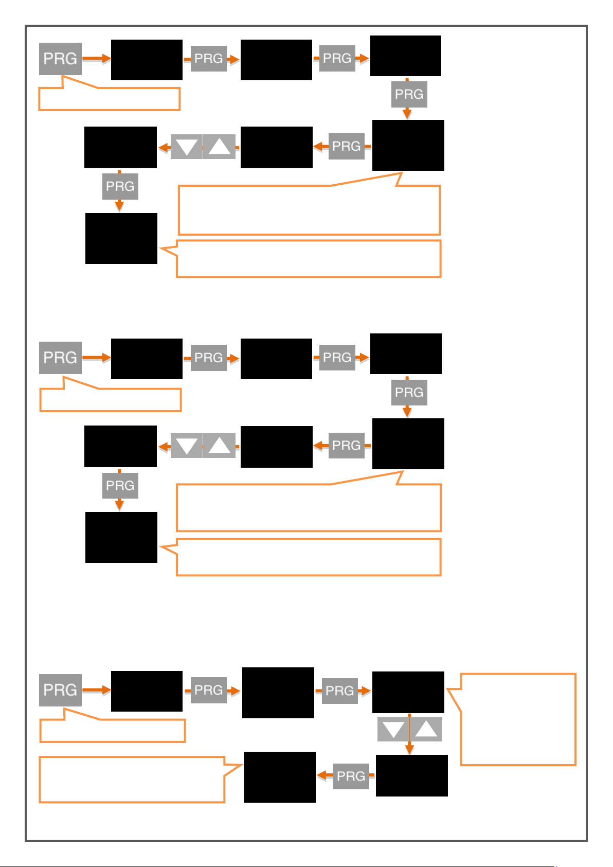
29
DISP
The new function you confirmed with the PRG button has been
set. You can return to run mode with the ESC button.
When you press and hold to the PRG key the value in the second
line starts blinking . You can select OFF, RISE or FALL functions
using the UP and DOWN buttons.
TARE
OFF
INPUT
EDGE
OFF
RISE
EDGE
RISE
DISP
The new filter value you confirmed with the PRG button has been
set. You can return to run mode with the ESC button.
When you press and hold to the PRG key the value in the second
line starts blinking. Enter the desired value using UP and DOWN
buttons.
TARE
100
FILTER
100
200
FILTER
200
DSP
Press and hold the PRG button.
REFRS
100
100
When you press and hold
to the PRG key the value
in the second line starts
blinking. Enter the
desired value using UP
and DOWN buttons.
110
REFRS
110
The new screen refresh rate you confirmed
with the PRG button has been set. You can
return to run mode with the ESC button.
Press and hold the PRG button.
Press and hold the PRG button.
INPUT
On the FILTR option, you can specify the how many miliseconds later tare signal will be checked. By
default, this value is 100 ms.
7.1.3. Screen Refresh Rate (REFRS)
Indicates how many milliseconds the value displayed on the screen will be refreshed. By increasing this
value, which is 100 ms by default, you can avoid or reduce the unstability on the screen, reducing the time
it takes your device's sensor to react.
KK-EPA.004 Rev No:0 28.09.18
Page 30
30
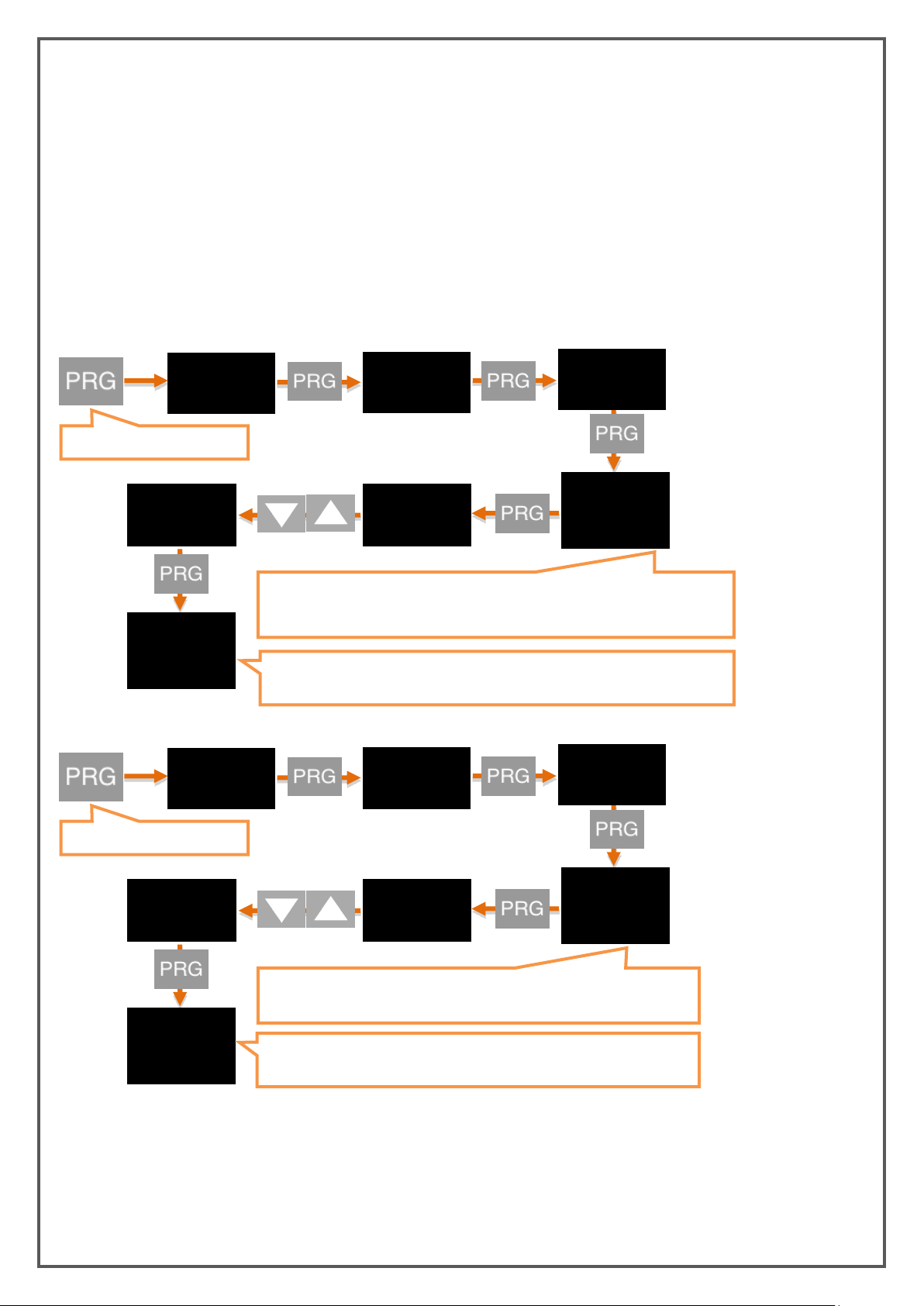
7.1.4. Prevention for Screen Flicker (FILTR)
DISP
Press and hold the PRG
When you press and hold to the PRG key the value in the second line starts
blinking.You can select OFF, RISE or FALL functions using the UP and DOWN
buttons.
FILTR
OFF
STATE
OFF
ON
STATE
On
AVRGE
The new screen refresh rate you confirmed with the PRG button has been set.
You can return to run mode with the ESC button.
DISP
Press and hold the PRG
When you press and hold to the PRG key the value in the second line
starts blinking. Enter the desired value using UP and DOWN buttons.
FILTR
400
COUNT
500
400
COUNT
400
AVRGE
The new screen refresh rate you confirmed with the PRG button has
been set. You can return to run mode with the ESC button.
Your EPA 200 device is programmed to display the signals it receives from the sensor connected to it by its
special algorithms and to show it in the most accurate way. But; You can solve this problem with the
flickering filtering method that appears on the screen for various reasons such as noise in the
surroundings, sensor disturbances. There are three filtering methods. You can use these filtering methods
alone or in two or three.
7.1.4.1. AVRGE (Average Calculation):
When you activate this filter by making STATE ON, your device will refresh the value displayed on the
screen after reading the number of values you can select in COUNT from the sensor. For example; When
COUNT is the default 500, your device will reset the value on the display by taking 500 times the sample
from the sensor. Accordingly, increasing COUNT values will reduce the flicker on the screen; however, it
will slow down your device's response to the rapid movements of the sensor.
KK-EPA.004 Rev No:0 28.09.18
Page 31
31
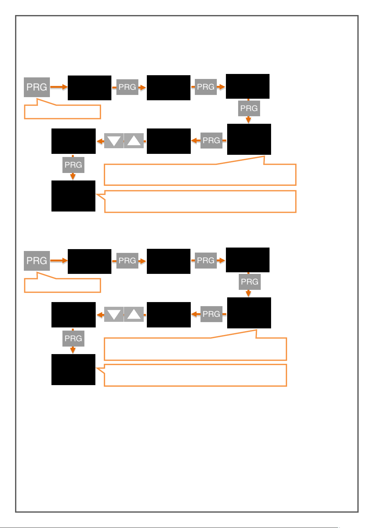
7.1.4.2. LQE (Linear Quadratic Estimation):
DISP
Press and hold the PRG
When PRG is pressed and entered, the value in the second line starts to
blinking. You can select ON or OFF by using DOWN and UP buttons.
FILTR
OFF
STATE
OFF
ON
STATE
On
LQE
The new screen refresh rate you confirmed with the PRG button has been set.
You can return to run mode with the ESC button.
DISP
Press and hold the PRG
When you press and hold to the PRG key the value in the second line
starts blinking. Enter the desired value using UP and DOWN buttons.
FILTR
400
COVAR
500
400
COVAR
400
LQE
The new screen refresh rate you confirmed with the PRG button has been
set. You can return to run mode with the ESC button.
You can also activate this filter, also known as the Kalman filter, by activating STATE ON. If you decrease
the COVARIANCE option of 500, the flicker on the screen will decrease; but your device will slow down the
response to the sensor's rapid movements.
7.1.4.3. LHYS (Hysteresis Filter):
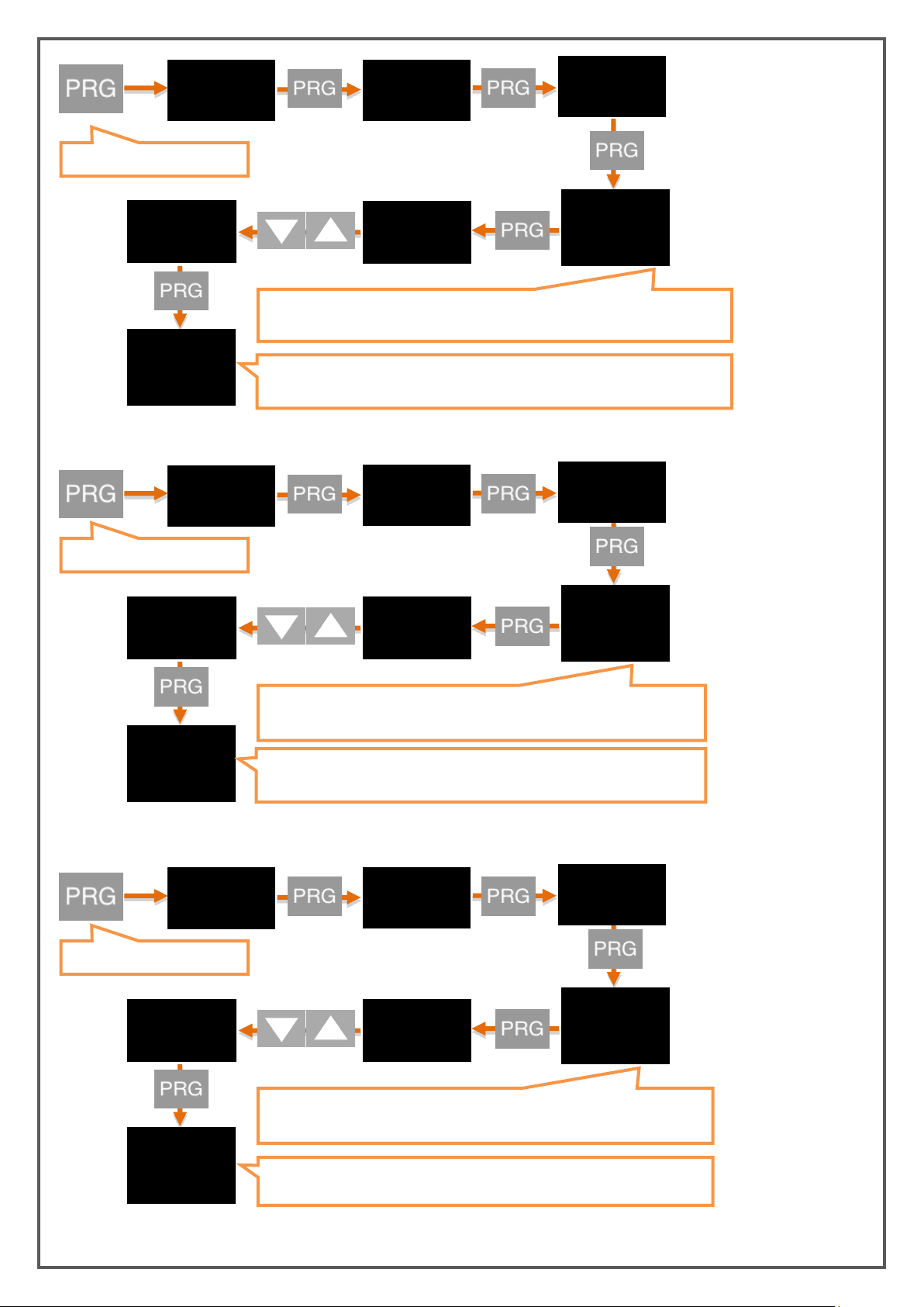
You can activate the hysteresis filter by making STATE ON. With this filter with two parameters named
Delta and A.Error, the raw value read from the sensor is not reflected on the screen until Delta is changed.
When the sum of the unprocessed values that are not reflected on the screen is up to A.Error, the display is
updated with the average of these values.
KK-EPA.004 Rev No:0 28.09.18
Page 32
32
DISP
Press and hold the PRG
When PRG is pressed and entered, the value in the second line starts to
blinking. You can select ON or OFF by using DOWN and UP buttons.
FILTR
OFF
STATE
OFF
ON
STATE
On
HYS.
The new screen refresh rate you confirmed with the PRG button has been set.
You can return to run mode with the ESC button.
DISP
Press and hold the PRG
When you press and hold to the PRG key the value in the second line
starts blinking. Enter the desired value using UP and DOWN buttons.
FILTR
4
DELTA
5
4
DELTA
4
HYS.
The new screen refresh rate you confirmed with the PRG button has been
set. You can return to run mode with the ESC button.
DISP
Press and hold the PRG
When you press and hold to the PRG key the value in the second line starts
blinking. Enter the desired value using UP and DOWN buttons.
FILTR
400
A.EROR
500
400
A.EROR
400
HYS.
The new screen refresh rate you confirmed with the PRG button has been
set. You can return to run mode with the ESC button.
KK-EPA.004 Rev No:0 28.09.18
Page 33
33
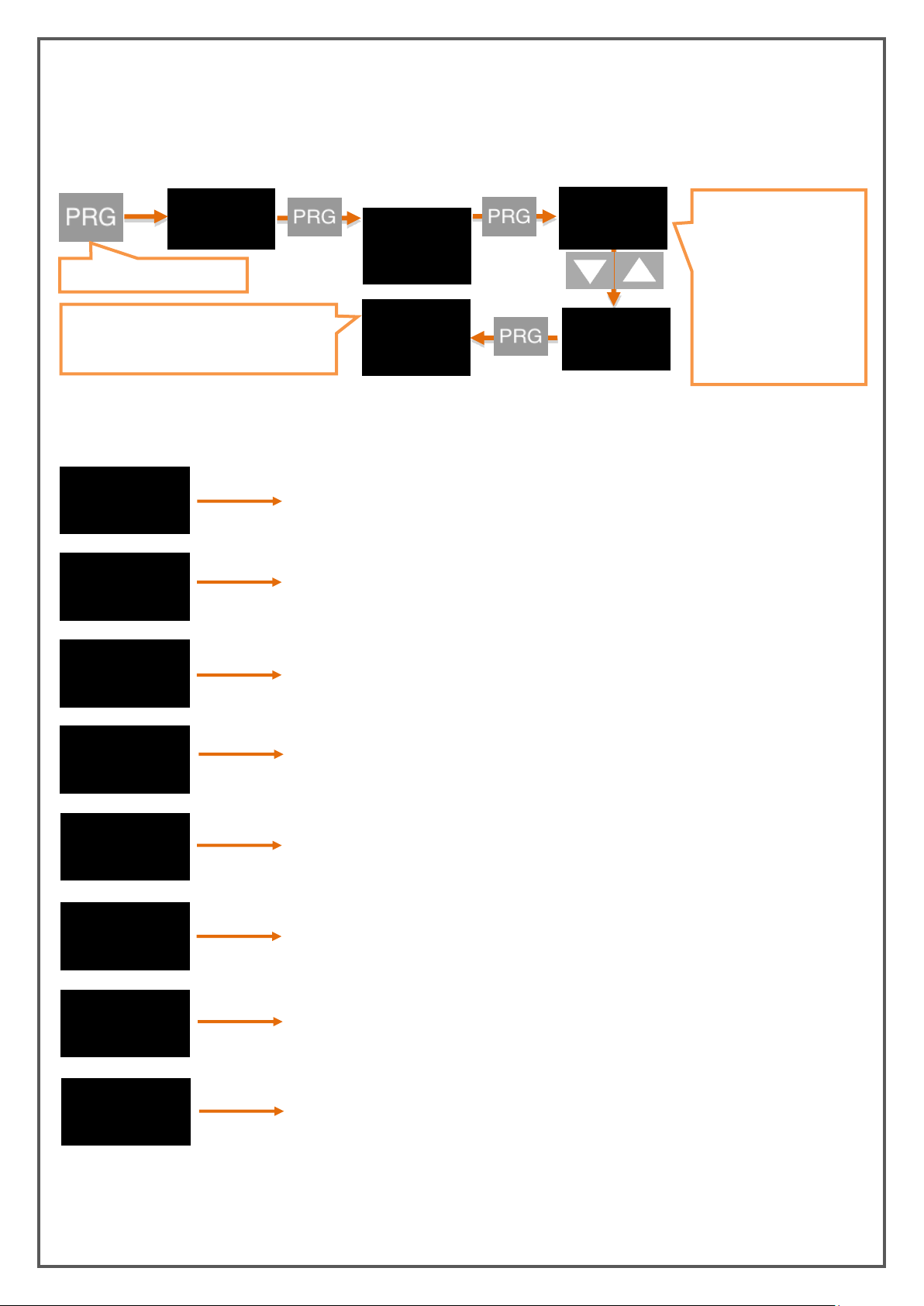
7.1.5. Identifying the Second Line on the Screen (LABEL)
Label
-off-
If the label is set to OFF, it will not write any values in line 2.
Label
Prb.tmp.
You can have the temperature information you get from the
thermocouple or RTD sensor that you can connect externally.
You can get the temperature information from the rtd element located
on the device internally.
Label
Amb.tmp.
Label
Can.dt1
You can provide to be shown data1 information through Can display via
digital communication
Label
Can.dt2
You can provide to be shown data2 information through Can display via
digital communication
Label
Set-1
You can have the 1st set values of the relay displayed on line 2
Label
Set-2
You can have the 2nd set values of the relay displayed on line 2
Label
Set-3
You can have the 3rd set values of the relay displayed on line 2
DISP
The new screen refresh rate you confirmed
with the PRG button has been set. You can
return to run mode with the ESC button.
Press and hold the PRG
OFF
When you press and hold
to the PRG key the value
in the second line starts
blinking. Enter the
desired label by using UP
and DOWN buttons. You
can see label options and
their explanation as
following.
TEMP.
LABEL
TEMP.
LABEL
OFF
By this menu, depending on the type of sensor that you connected to the input of the EPA200, you can
select which unit to write on the 2nd line of the display. OFF is selected as the factory default. In this case
the second row is empty.
Label Types:
KK-EPA.004 Rev No:0 28.09.18
Page 34
34
Label
preset
You can have the Preset value (PRSET) set for the Tare function to be shown
in Line 2.
-1.34
-LO-
65.65
-HI-
51.42
TEMP
You can also select one of the fixed font options, such as various units or label numbers.
8. OPERATION MODE FUNCTIONS
Your EPA 200 process controller operates in two different modes.
Your device operates in the programming mode when the settings are changed in the operation mode and
the parameters are changed in the startup screen where the reading value is displayed on the sensor. This
section describes the functions in operation mode.
8.1. Tare (Reset ) Fonction
*** Operates only when the Tare function is active. Please refer to the description of the functions or to
activate. 7.1.2 Reset (Tare).
Each time the device is in operating mode, pressing the UP button will activate Tare according to the type
of tare function selected and the Tare status led will light.
8.2. Viewing Maximum and Minimum Values which are read
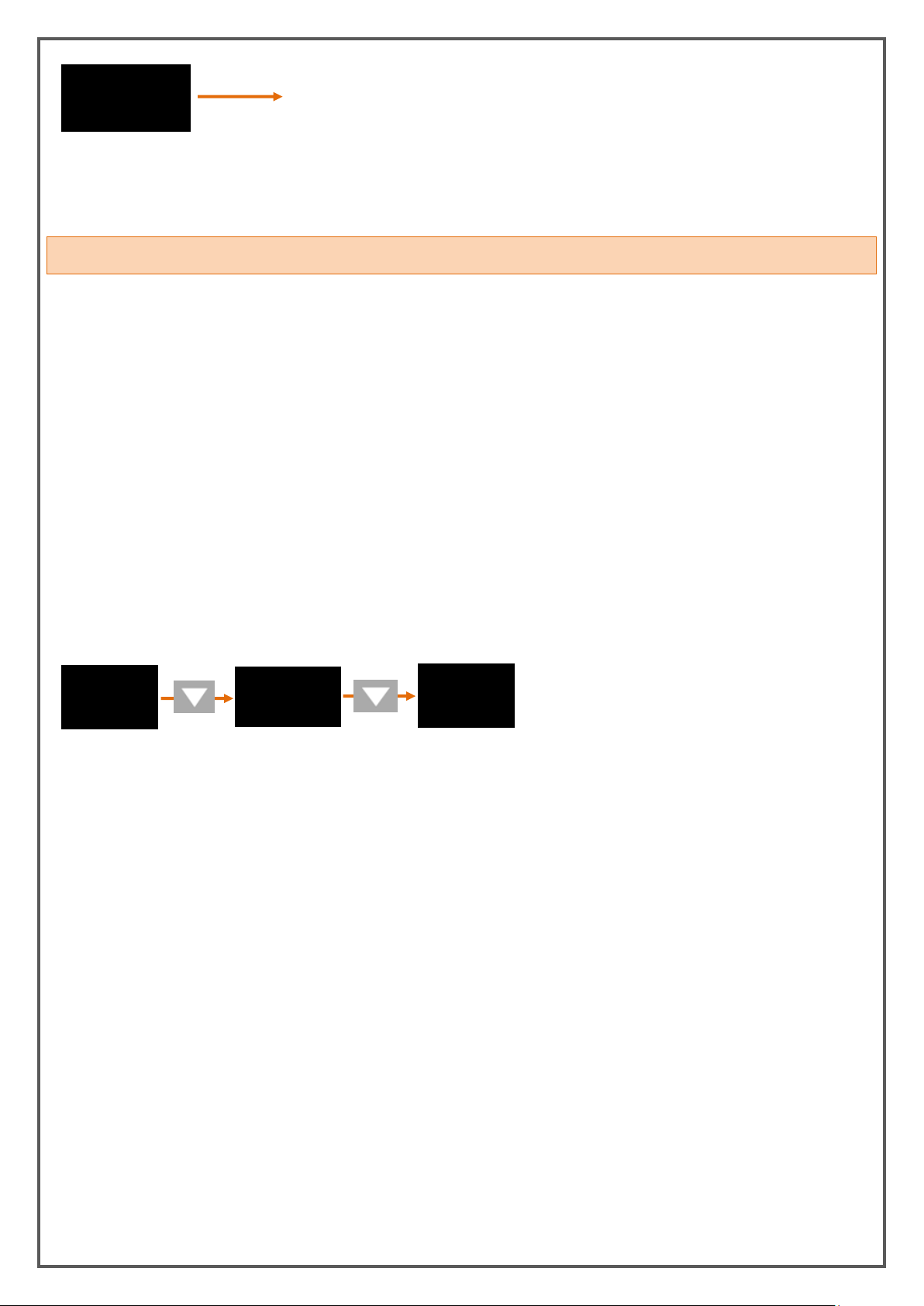
When you press the DOWN button while the device is in operation mode, you can see the minimum
(minimum) value read from the moment the device starts. When you press the DOWN button again, you
can see the highest (maximum) value read from the moment the device starts.
Not: You can use the ESC key to erase the (minimum) and (maximum) values in the memory.
KK-EPA.004 Rev No:0 28.09.18
Page 35
35
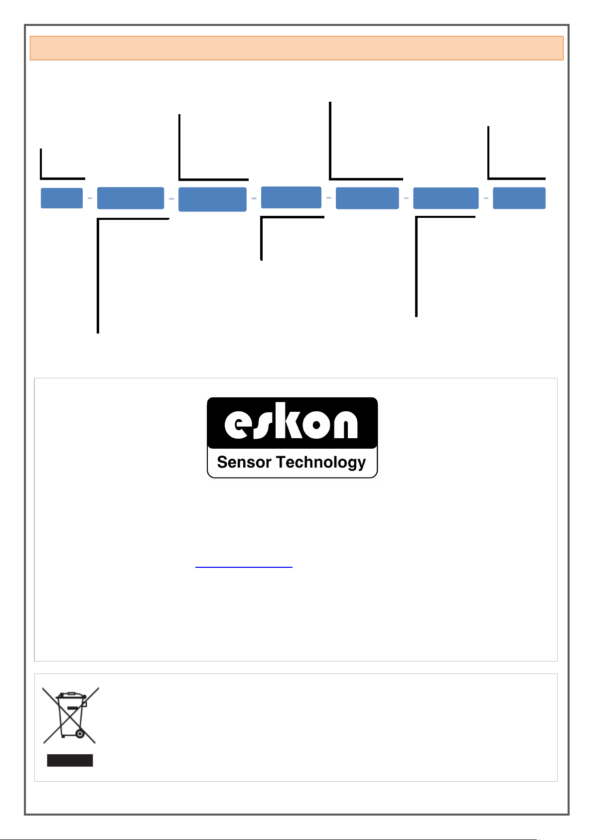
9. PRODUCT CODING
Model
EPA 200
Input Signal Type
P - Potantiometric
V - 0-10V
A - 4-20mA
A0 - 0-20mA
M - 3.33mV/V
L - 2mV/V
N - 2.5mV/V
C - CANopen
Supply Voltage
220V - 220 VAC
24V - 24 VAC/DC
Communication Type
Null - No Communication Type
S1 - RS232 communication
S2 - RS485 communication
S3 - USB communication
S4 - CANopen communication
Analog Output Signal
Type
Null - No Analog Output
V0 - 0-10V output
V1 - 0-5V output
V3 - 0.5-4.5V output
A0 - 0-20mA output
A4 - 4-20mA output
When ordering your EPA 200 process controller, you can use the following coding format.
Sample Product Code: EPA200-V-TR1-220V-S2-A4-T
External Tare
Boş - No External
Tare
T - External Tare
Temperature Input
Null - No Temperature Input
PT1 - PT100
PT2 - PT1000
TR1 - Thermocouple
Manufacturer Firm’s Title, Address Details
Manufacturer Firm: ATEK SENSÖR SANAYİ VE TİCARET A.Ş.
Address: Tuzla KOSB Organize Sanayi Bolgesi Melek Aras Bulvari, No:67 34956 Tuzla-Istanbul / TURKEY
TEL: +90 0216 399 44 04 FAX: +90 0216 399 44 02
Web: www.ateksensor.com E-mail: [email protected]
Authorized Service’s Title, Address Details
Authorized Service: ATEK SENSÖR SANAYİ VE TİCARET A.Ş.
Address: Tuzla KOSB Organize Sanayi Bolgesi Melek Aras Bulvari, No:67 34956 Tuzla-Istanbul / TURKEY
TEL: +90 0216 399 44 04 FAX: +90 0216 399 44 02
E-mail: [email protected]
Disposal of Packagings: Packaging materials consist of recyclable materials. For providing
recycling, please dispose waste packagings to collecting points of authorized recycling facilities.
Disposal of E-Waste: This device is in conformity with WEEE Directive and consists of recyclable
materials. This product should not be disposed with general waste for preventing negative effects
on enviroment and human health. This product should be disposed to collecting points of
authorized recycling facilities. Further information can be reached from authorized unit.
EPA200 X
X
XXX
XX XX X
KK-EPA.004 Rev No:0 28.09.18
Page 36
36
10. WARRANTY CERTIFICATE
Signature, Cachet
Manufacturer Company’s:
Name: Alfa Elektronik Sensör Sanayi ve Ticaret A.Ş.
Address: Tuzla KOSB Organize Sanayi Bölgesi Melek
Aras Bulvarı, No:67 34956 Tuzla – Istanbul / TURKEY
Seller Company’s:
Name:
Address:
Phone:
FAX:
E-mail:
Invoice Date and No:
Delivery Date and Address:
Signature, Cachet
Product Brand: ESKON
Product Code: EPA-200
Serial No:
Warranty Time: 2 Years
This product is guaranteed for 2 years against manufacturing defects.
Non-warranty situations:
- Mechanical damages
- Damages in case of transportation
- User errors
Other cases than these cases are under the manufacturer’s warranty.
KK-EPA.004 Rev No:0 28.09.18
 Loading...