

Page 1
Instruction Book Snow Thrower Model 6400
Read and keep this book for future reference. This book contains important information on
SAFETY, ASSEMBLY
OPERA
TION, AND MAINTENANCE.
,
OM-6400
Page 2

NOTE: This unit is equipped with an internal combustion engine
and must not be used on or near any unimproved
forest-covered, brush-covered or grass-covered land unless
the engine’s exhaust system is equipped with a spark arrester
meeting applicable local or state laws (if any). If a spark arrester
is used, it must be maintained in effective working order by the
operator.
In the State of California, the above is required by law (Section
4442 of the California Public Resources Code). Other states
may have similar laws. Federal laws apply on federal lands. See
an Authorized Service Center for a spark arrester for the
muffler.
Engine Exhaust, some of its constituents, and
certain vehicle components contain or emit
chemicals known to the State of California to
cause cancer and birth defects or other reproductive harm.
Battery posts, terminals and related accessories contain lead and lead compounds, chemicals known to the State of California to cause
cancer and birth defects or other reproductive
harm. WASH HANDS AFTER HANDLING.
OM6400
2
Page 3
1
5
13
14
2
9
12
8
6
10
11
1
2
2
3
4
16
7
1
11
18
17
3
2
1
1
7
1
12
15
4
3
9
10
1
7
6
2
5
4
16
5
15
6
OM6400
7
6
5
3
Page 4
Page 5
13 14
15
13
9
12
3
17
2
1
18
15
6
3
5
10
4
16
13
14
11
16
2
8
4
17
2
4
3
5
3
18
OM6400
“A”
5
Page 6
19
4
6
8
1
8
9
20
5
4
21
2
3
4
4
5
3
23
11
3
11
12
22
6
24
OM6400
10
2
3
15
6
Page 7
11
25
26
16
19
13
13
7
17
16
17
14
7
7
20
8
OM6400
7
Page 8
27
2- 9524
2- 3943
2 - 73826
1- Extension cord
OM6400
8
Page 9
CONTENTS
PRODUCT INFORMATION 9
OWNER’S INFORMATION 9
INTERNATIONAL PICTORIALS 10
ASSEMBLY 12
OPERATION 12
MAINTENANCE 15
TROUBLE SHOOTING CHART 18
TWO YEAR LIMITED WARRANTY
Ardisam, Inc. warrants to the original purchaser
that this unit shall be free from defects in
aterial and workmanship under normal use
m
nd service for a period of Two (2) Years
a
the date of purchase; however, th
does not cover engines, accessories (such as
electric starters) and Normal Wear Parts (except
s noted below) For additional information,
a
see the warranties covering these particular
parts. If you are uncertain whether your unit
contains or is equipped with one or more of
these parts, consult your dealer prior to
from
is warranty
purchase. Subject to the terms and conditions
oted in this Limited Wa
n
option, repair or replace at no cost to the original
urchaser any part covered by this Limited
p
rranty during the applicable warranty period.
Wa
Normal We
augers, shear pins, tires and headlights. These
arts are warranted to be free from defects in
p
aterial and workmanship as delivered with the
m
roduct. Any claim for repair or replacement of
p
ormal We
N
(30) days of th
involving damage caused from material use,
buse or misuse will be honored.
a
This Ardisam, Inc. Two (2) Ye
Warranty is your exclusiv
this warranty is void or does not apply to any
nit that has been tampered with, altered,
u
isused, abused or used for rental or other
m
ommercial and/or professional
c
(non-homeowner) uses. Your warranty does not
c
over minor mechanical adjustments which are
n
ot due to any defect in material or
workmanship. For assistance in making such
adjustments, consult your Instruction Book.
To make a claim under this Ardisam, Inc.
Year Limited Warranty
authorized in advance),the defective part along
with your proof of purcha
Service center near you. To locate the nearest
ar Parts are defined as drive belts,
ar Parts must be made within thirty
e date of purchase. No claims
rranty, we shall, at our
ar Limited
e remedy; however,
return the unit (or if
,
se to an Authorized
Two (2)
ENGLISH
uthorized Service center, call Ardisam customer
a
service at 1800-345 6007. If you return the entire
unit, We will repair the unit. If we authorize the
return of the defective part only,we will either
eplace or repair the part .This Ardisam, Inc.
r
Two (2) Year Limited Warranty
pecific legal rights, and you may also have
s
other rights which vary from state to state.
Limited Warranty is given in lieu of all other
e
xpressed and implied warranties including
the implied wa
.
warranty of fitne
y
ou need additional information on this written
If
warranty or assistance in obtaining service,
write:
info@ Ardisam.com
Ardisam.Inc
1690 EIm Street
.O.Box 666
P
Cumberland,WI54829
Phone
715-822-2415
Fax: 715-822-2223
1-800-345-6007
www
rranty of merchantability and
ss for a particular purpose.
.ardisam.com
gives you,
This
PRODUCT INFORMATION
The owner must be certain that all the product
information is included with the unit. This
i
nformation includes the INSTRUCTION
BOOKS, th
WA
included to make sure state laws and other laws
a
re followed.
e REPLACEMENT PARTS and the
RRANTIES. This information must be
OWNER’S INFORMATION
This instruction book is written for a person with
some mechanical ability. Like most service
b
ooks, not all the steps are described. Steps on
h
ow to loosen or tighten fasteners are steps
a
nyone can follow with some mechanical ability.
R
ead and follow these instructions before you
u
se the unit.
Know your product:
and how the unit operates, you will get the best
p
erformance. As you read this manual, compare
t
he illustrations to the unit. Learn the location
a
nd the function of the controls. To
an accident, follow the operating instructions
a
nd the safety rules. Keep this manual for future
If you understand the unit
help prevent
reference.
IMPORTANT:
and are sold in cartons. It i
the owner to make sure the assembly instruct
ions in this manual are exactly followed. Other
u
nits are purchased in an assembled condition.
On assembled units, it is the responsibility of the
owner to make sure the u
sembled. Th
unit according to the instructions in this manual
b
efore it is first used.
WA
RNING: Look for this symbol to indicate
important safety precautions. This symbol
indicates: “Attention! B
Safety Is At Risk.”
Many units are not assembled
s the responsibility of
nit is correctly as-
e owner must carefully check the
ecome Alert! Your
Responsibility Of The Owner
The responsibility of the owner is to
follow the instructions below.
1. Carefully read and follow the rules for safe
operation.
2. F
ollow all the assembly and preparation
instructions.
3. Inspect the unit.
4. M
ake sure that the operator of the unit
knows how to correctly use all standard
a
nd accessory equipment.
5. O
perate the unit only with guards, shields,
and other safety items in place and working
correctly.
6. C
orrectly adjust the unit.
7. S
ervice the unit only with authorized or ap-
proved replacement parts.
8. C
omplete all maintenance on the unit.
Environmental Awareness
Do not fill the engine’s fuel tank completely
full.
Drain fuel for off-season storage.
Use only unleaded gasoline.
Service the air cleaner regularly.
Change oil regularly. Use 5W-30 oil.
Tune-up the engine regularly.
Keep equipment in efficient operating
condition.
Dispose of used engine oil properly.
OM6400
9
Page 10
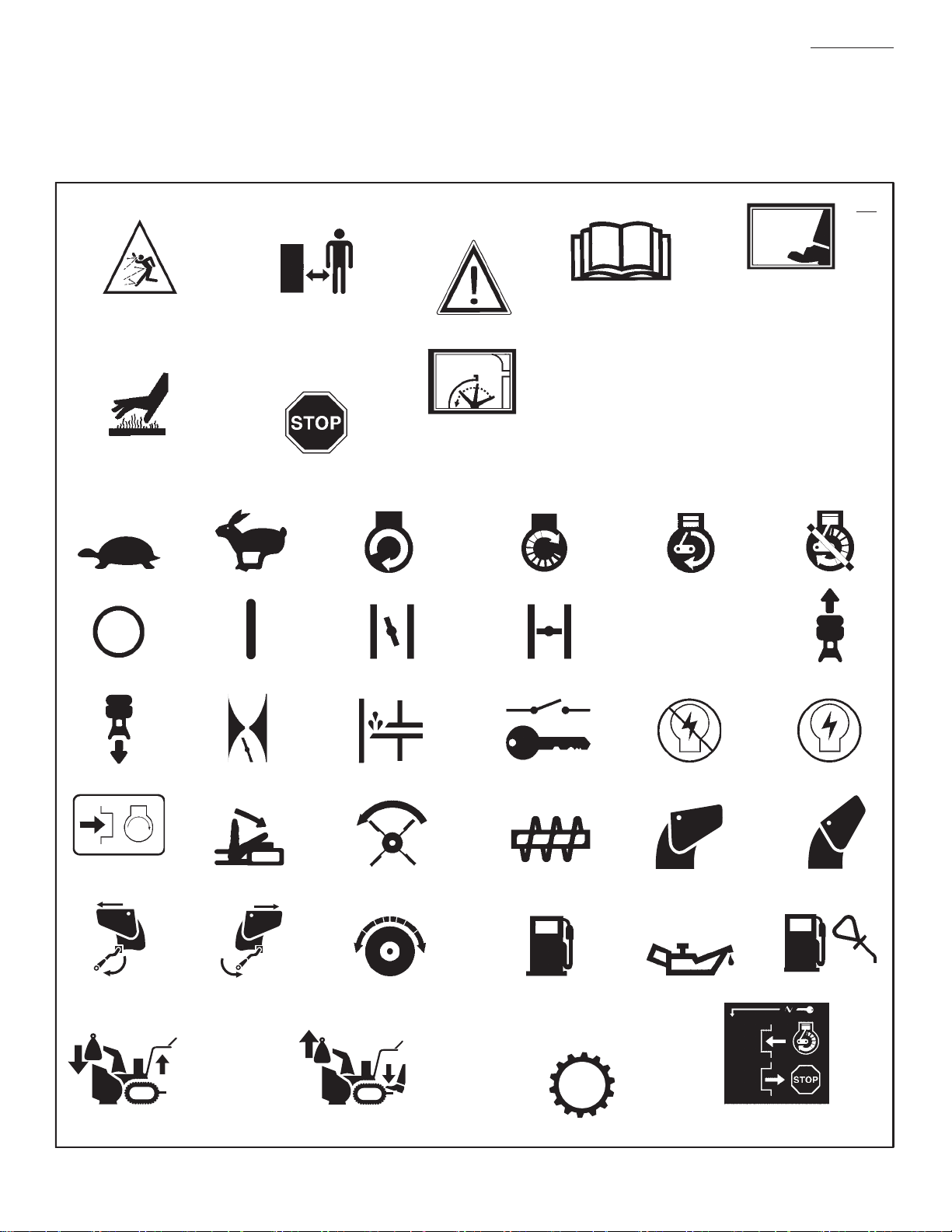
INTERNATIONAL PICTORIALS
IMPORTANT: The following pictorials are located on your unit or on lit
with the product. Before you ope
unit, le
arn and understand the purpose for
each pictorial.
erature supplied
rate the
ENGLISH
Safety Warning Symbols
DANGER
Thrown Objects.
K
eep Bystanders Away.
WARNING
Hot Surface
DANGER
Thrown Objects.
K
eep Bystanders Away.
STOP
WARNING
DANGER
Stop The Engine
Before Unclogging
Discharge Chute!
IMPORTANT
Read Owner’s
Before Operating
T
his Machine.
Control And Operating Symbols
Slow Fast Electric Start Engine Start Engine Run
Manual
DANGER
Avoid Injur
Rotating Auger. Keep
H
ands, Fe
Clothing Away.
y From
et And
Engine Off
28
Engine Stop On Choke Off Choke On
Reverse
Push To
Discharge LEFT Discharge RIGHT
Engage
Electric Starter
KGS
Throttle Primer Button Ignition Key Ignition Off Ignition On
Engage
Auger Clutch
Drive Clutch
KGS
Auger Collector
Fuel Oil Fuel Oil Mixture
N
Neutral
Discharge DOWN Discharge UP
Forward
Weight Transfer
Lift Handle To Engage
OM6400
Weight Transfer
Depress Pedal To
Disengage
10
Transmission
Insert To Run, Pull Out To Stop.
Ignition Key
Page 11

Safe Operation Practices for Snow Throwers
As Recommended By: American National Standards Institute.
ENGLISH
IMPORTANT: Safety standards require operator
presence controls to minimize the risk of injury.
Yo
ur snow thrower is equipped with such controls. Do not attempt to defeat the function of the
o
perator presence control under any circum-
stances.
Training
1. Read the operating and service instruction
manual carefu
ontrols and the proper use of the equip-
the c
ment. Know how to stop the unit and disen-
age the contr
g
ever allow children to operate the equip-
2. N
ment. Never allow adults to operate the
quipment without proper instr
e
eep the area of operation clear of all per-
3. K
ns, particularly small children and pets.
so
rcise caution to avoid slipping or falling
4. Exe
ecially when operating in reverse.
esp
lly. Be thoroughly familiar with
ols quickly.
uction.
Preparation
1. Thoroughly inspect the area where the equip-
ment is to be used a
eds, boards, wires, and other foreign ob-
sl
jec
ts.
isengage all clutches before starting the en-
2. D
gine (motor
3. Do n
ing adequate winter outer garments. We
footwear that will improve footing on slippery
sur
andle fuel with care; it is highly flammable.
4. H
a. U
b. Never r
c. Fill fuel tank outdoors with extreme care.
d. Replace fuel cap securely and wipe up
e. Never s
f. Check f
5. F
or all units with electric starting motors use
elect
CS
been i
ection authorities.
sp
djust the snow thrower height to clear gravel
6. A
or c
).
ot operate the equipment without wear-
faces.
se an approved fuel container.
emove fuel tank cap or add fuel to
a running engine (motor) or hot engine
(motor).
ever fill fuel tank indoors.
N
spilled fuel.
in the tank inside of a building where
fumes m
uel supply before each use, allowing
space for expansion as the heat of the
engine (
to expand.
ric starting extension cords certified
A/UL. Use only with a receptacle that has
nstalled in accordance with local in-
rushed rock surface.
nd remove all doormats,
ar
tore fuel or snow thrower with fuel
ay reach an open flame or spark.
motor) and/or sun can cause fuel
7. Never
8. L
9. A
attempt to make any adjustments
while the engine (motor) is running (ex
when speci
turer).
et engine (motor) and snow thrower adjust
to outd
ear snow.
cl
lways wear safety glasses or eye shields
during o
justm
objects th
thrower.
fically recommended by manufac-
oor temperatures before starting to
peration or while performing an ad-
ent or repair to protect eyes from foreign
at may be thrown from the snow
cept
Operation
1. Do not operate this machine if you are taking
drugs or other medicat
ess or affect your ability to operate
drowsin
this machi
2. Do n
or phy
safely.
3. Do not put hands or feet near or under rotat-
ng p
i
ing at
4. Exe
or cros
Stay alert for hidden hazar
5. A
(motor), remove the wire from the spark plug,
th
damage, and repair t
sta
6. If the unit should sta
stop the engine (motor) and check immedi-
tely for the cause. Vi
a
warning of t
7. S
the o
auger/impeller housi
and when maki
or insp
8. W
cer
parts have sto
engaged. Dis
ke
preve
9. Take all pos
the snow thrower unattended. Dise
auger/ impeller, s
move key.
0. Do n
1
when s
ansporting the snow thrower in or out of the
tr
building. O
fu
MONOXIDE, an ODORLESS and DEADLY
G
ne.
ot use this machine if you are mentally
sically unable to operate this machine
arts. Keep clear of the discharge open-
all times.
rcise extreme caution when operating on
sing gravel drives, walks or roads.
fter striking a foreign object, stop the engine
oroughly inspect snow thrower for any
rting and operating the snow thrower.
rouble.
top the engine (motor) whenever you leave
perating position, before unclogging the
ections.
hen cleaning, repairing, or inspecting, make
tain the auger/impeller and all moving
connect the spark plug wire and
ep the wire away from the spark plug to
nt accidental starting.
sible precautions when leaving
ot run the engine (motor) indoors, except
tarting the engine (motor) and for
pen the outside doors; exhaust
mes are dangerous (containing CARBON
AS).
ion which can cause
ds or traffic.
he damage before re-
rt to vibrate abnormally,
bration is generally a
ng or discharge chute
ng any repairs, adjustments,
pped and all controls are dis-
ngage the
top engine (motor), and re-
11. Do not clear snow acr
rcise extreme caution when changing
Exe
on on slopes. Do not attempt to clear
directi
ep slopes.
ste
12. N
ever operate the snow thrower without
proper guards, plates or oth
tive devices in p
13. N
ever operate the snow thrower near enclosures, automobiles, window wells, drop- offs,
a
sn
pets away.
4. Do not ove
1
te
15. N
sp
and use c
16. N
anyo
17. D
when snow thrower is transp
use.
8. U
1
proved by the manufact
thrower (such as tire chains, elect
ect.).
9. N
1
visib
ing a
Walk;
20. Do n
balance at
21. E
ing surfaces.
2. This snow thrower is for use on sidewalks,
2
driveways and other ground level surfaces.
3. D
2
above ground level such as roofs of resid
structures or buildings.
ike without proper adjustment of the
nd the l
ow discharge angle. Keep children and
mpting to clear snow at too fast a rate.
ever operate the machine at high transport
ever direct discharge at bystanders or allow
isengage power to the collector/impeller
se only attachments and accessories ap-
ever operate the snow thrower without good
xercise caution if operating on steep slop-
o not use the snow thrower on surfaces
ences, garages, porches or other such
rload the machine capacity by at-
eeds on slippery surfaces. Look behind
are when backing up.
ne in front of the unit.
ility or light. Always be sure of your foot-
nd keep a firm hold on the handles.
never run.
ot over- reach. Keep proper footing and
all times.
oss the face of slopes.
er safety protec-
lace.
orted or not in
urer of the snow
ric start kits,
Maintenance And Storage
1. Check shear bolts and other bolts at frequent
2. N
3. A
4. M
5. R
ls for proper tightness to be sure the
interva
equipment is in safe worki
ever store the snow thrower with fuel in the
de a building where ignition sources
tank insi
are prese
heaters, cl
the engine (motor) to co
any encl
for important details if the snow thrower is to
be s
bels, as neces
throwing snow to preve
auger/impeller.
nt such as hot water and space
othes dryers, and the like. Allow
osure.
lways refer to operator’s guide instructions
tored for an extended period.
aintain or replace safety and instruction la-
sary.
un the snow thrower a few minutes after
ng condition.
ol before storing in
nt freeze- up of the
OM6400
11
Page 12
Fuel Switch
Shuts OFF/ON flow from tank
Page 13
How To Go Forward or Backward
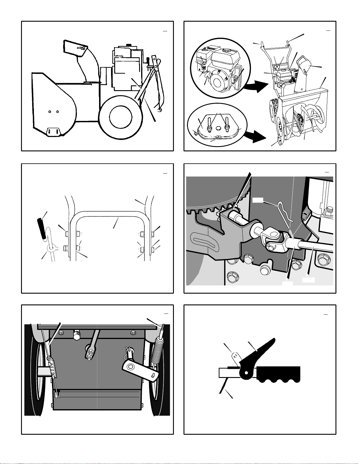
(Figure 2)
1. To change the ground speed, first release the
traction drive lever (1) a
speed shift lever (6)
2. G
round speed is determined by snow conditions. Select the speed by moving the speed
shift lever (6)
the shift lever plate.
S
peed 1, 2 We
Speed 3 L
Speed 4 Ve
Speed 5, 6 Tr
go forward, engage the traction drive
3. To
lever (1).
as the snow thrower starts to move forward.
G
uide the snow thrower by moving the han-
d
le either left or right. Do not attempt to push
the snow thrower.
4. To
go backward, release the tractor drive
lever (1).
ove the speed shift lever (6) into either
5. M
first or second reverse.
6. E
ngage the traction drive lever (1).
IMPORTANT: Do not move the speed shift
lever (6) while the traction drive lever (1) is
engaged.
into the appropriate notch on
ight
Maintain a firm hold on the handle
nd then move the
to the desired speed.
t, Heavy
ry Light
ansport only
How To Throw Snow (Figure 2)
1. Engage the auger drive lever (5).
2. To
stop throwing snow, release the auger
drive lever (5).
WARNING: The operation of any
snow thrower can result in foreign
obje
which can result in severe eye damage.
A
lways wear safety glasses or eye shields
while operating the snow thrower. We reco
mmend standard safety glasses or use a
w
ide vision safety mask over your glasses.
cts being thrown into the eyes,
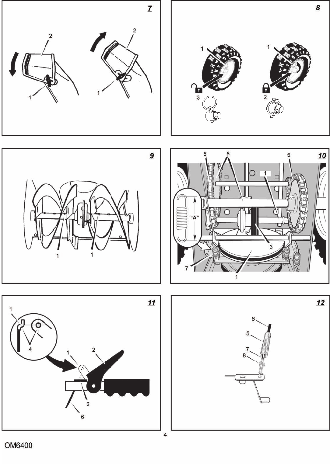
How To Use The Wheel Lockout Pin
(Figure 8)
1. The left hand wheel is secured to the axle
with a
klick pin (1). This unit was shipped
with this k
in the l
or ease of maneuverability in light snow
2. F
conditions, change the k
unlocked position (3).
3. Disconnect the k
locked position (2).
through the unlocked axle hole only.
is now in the single wheel drive unlocked
position (3).
lick pin (1) through the wheel hole
ocked position (2).
lick pin (1) to an
lick pin (1) from the wheel
Push the klick pin (1)
The unit
Before Starting The Engine
1. Before you service or start the engine, familiarize yourself with the snow thrower. Be
s
ure you understand the function and loca-
t
ion of all controls.
2. C
heck the tension of the clutch cable before
starting the engine. See “
Clutch Cable” in the Maintenance section of
t
his manual.
ake sure that all fasteners are tight.
3. M
ake sure the height adjust skids are proper-
4. M
ly adjusted. See “How To Adjust The Height
O
f The Skids” in the Maintenance section of
t
his manual.
How To Adjust The
OM6400
5. Check the air pressure in the tires. The correct air pressure is 14 PSI (1 BAR) to 17 PSI
1.25 BAR). Do not exceed the maximum
(
a
mount of air pressure shown on the side of
t
he tire.
How To Stop The Engine (Figure 2)
To stop the engine, Turn the ON/OFF switch
or key
and remove the ignition
Keep the
The engine will not start without the
ion key (8).
t
ignition key (8)
key (8)
in a safe place.
igni-
How To Start The Engine (Figure 2)
Models equipped with an Electric Starter
WARNING: The star
with a thre
plug and is designed to operate on
1
20 volt A.C. household current. The power
c
ord must be properly grounded at all times
to
avoid the possibility of electrical shock
which can injure the ope
low all instruct
Engine” section. Make sure that your house
w
iri
ng is a three- wire grounded system. If
you are not sure, ask a licensed electrician.
If your house wire system is not a
t
hree- w
ire grounded system, do not use
this e
lectric starter under any conditions. If
your system is grounded but a three- h
grounded r
the e
ngine, have a three- hole grounded receptacle
To
ways c
box (11) on the engine first. Then, plug the
o
ceptacle. W
cord, always unplug t
three- h
How To Start A Cold Engine (Figure 2)
1. C
2. F
3. M
4. M
5. Insert th
6. M
7. (Electric Start) C
8. (Electric Start) Pl
installed by a licensed electrician.
connect a 120 volt A.C. power cord, al-
onnect the power cord to the switch
ther end into the three- h
ole grounded receptacle first.
heck the engine oil.
ill the fuel tank with regular unleaded petrol.
See “How To
ake sure the traction drive lever (1) and
the a
uger drive lever (5) are in the disen-
gaged (released) position.
ove the throttle control (13) to the fast
position.
e ignition key (8) into the ignition
slot. M
ake sure the ignition key (8) snaps
into place. Do not turn the ignition key (8).
R
emove the extra ignition key and keep in a
s
afe place.
ove the choke control (14) to the full
choke position.
the switch box (11
power cord into a three-hole, grounded 120
VOLT, A.C. receptacle. (See the WARNING
in this section).
e- wire power cord and
ions in the “How To Start The
eceptacle is not available to start
hen disconnecting the power
Prepare The Engine”.
onnect the power cord to
ug the other end of the
ter is equipped
rator. Carefully fol-
ole
ole grounded re-
he end from the
) located on the engine.
13
ENGLISH
9. (Electric Start) P
button (10) u
crank for more than 10 seconds at a time.
The electric starter is thermally protected. If
the electric starter overheats, it will automatic
ally stop and can only be restarted when it
h
as cooled to a safe temperature. A wait of
a
bout 5 to 10 minutes is required to allow the
.
electric starter to cool.
1
0. (Recoil Start) R
handle (12). D
handle (12) to snap back. Slowly return the
r
ecoil s
tarter handle (12).
f the engine does not start in 5 or 6 tries,
11.I
See the “Tr
tions.
12.(Electric Start) W
lease the electric start but
move the c
position. When the engine runs smoothly,
m
ove the
tion.
13.(Electric Start) First disconnect th
cord from the three-hole receptacle. Then,
d
isconnect the power cord from the switch
box (11).
NOTE: In temperatures below 0 F, allow
the engine to warm up for several minutes
before blowing snow.
1
4.W
hen throwing snow, always run the engine
with the throttle control (13)
tion.
WARNING: Never run the engine
ndoors or in enclosed, poorly ven-
i
t
t
d
l
located on the engine or the snow thrower.
The temperature of muffler and ne
areas may exceed 150°F. Av
areas.
How To Start A Warm Engine (Figure 2)
If an engine has been running and is still warm,
eave the c
l
and d
engine fails to start, fo
To
NOTE: Do not use the primer button (9) to
tart a warm engine.
s
How To
Starter (Figure 2)
If the electric starter is frozen and will not turn
the engine, follow the instructions below.
1. P
2. Quickly release the r
If the engine still fails to start, repeat the two pre-
ious steps until the engine starts. Then, contin-
v
e with the directions “How To Start A Cold
u
Engine”.
To help prevent possible freeze-up of the
ecoil starter and engine controls, proceed
r
a
s follows after each snow removal job.
ilated areas. Engine exhaust con-
ains carbon monoxide, an odorless and
eadly gas. Keep hands, feet, hair and
oose clothing away from any moving parts
hoke control (14) in the off position
o not push the primer button (9). If the
Start A Cold Engine”.
Start An Engine With A Frozen Electric
ull out the recoil starter handle (12) as far
as possible.
(12).
Allow the recoil starter handle (12) to
snap back against th
ush on the electric start
ntil the engine starts. Do not
apidly pull the recoil starter
o not allow the recoil starter
ouble Shooting Chart” Instruc-
hen the engine starts, re-
ton (10) and
hoke control (14) to 1/2 choke
choke control (14) to the off posi-
e power
in the fast posi-
arby
oid these
llow the instructions “How
ecoil starter handle
e recoil starter.
Page 14

1. With the engine running, quickly pull the recoil starter handle (12)
with a continuous full arm stroke. Th
produce a loud clattering sound that is not
h
armful to the engine or starter.
2. S
top the engine. Wipe all snow and moisture
from the carburetor cover, control levers and
cables. Also move the throttle control (13),
c
hoke control (14),
dle (
12) several times.
three or four times
is will
and recoil starter han-
How To Remove Snow or Debris From
The Auger Housing
WARNING: Do not attempt to rem
ove snow or debris that may be-
c
without taking the following precautions.
1. Release the auger drive lever (5).
2. M
ome lodged in auger housing
ove the throttle control (13) to the stop
position.
(Figure 2)
3. R
emove (do not turn) the ignition key (8).
4. Disconnect the spark plug wire.
o not place your hands in the auger hous-
5. D
ing (4)
or the discharge chute (3). Use a
pry bar to remove any snow or debris.
Snow Throwing Tips
1. For maximum snow thrower efficiency,
change the ground speed, NEVER change
t
he engine speed. The engine is designed to
d
eliver maximum performance at full throttle
a
nd must be run in the fast position at all
t
imes. In deep, freezing, or wet snow,
forward speed. If the wheels slip, also reduce
f
orward speed.
ost efficient snow throwing is accomplished
2. M
when the snow is removed immediately after
if fa
lls.
3. For complete snow removal, slightly overlap
ach previous path.
e
reduce
ENGLISH
4. Whenever possible, discharge the snow
d
own wind.
5. For normal usage, set th
scraper bar is 1/8” above the skids. For extremely hard-packed snow surfaces, adjust
the skids upward so that th
touches the ground.
ocks and gravel must not be picked up and
6. R
thrown by the machine. On gravel or crushed
rock surfaces, set the skids at 1-1/4 inch bel
ow the scraper bar. See “How To Adjust The
H
eight Of The Skids” in the Maintenance
section.
7. A
fter each snow throwing job, allow the engine to idle for a few minutes. The snow and
a
ccumulated ice will melt off
lean the snow thrower after each use.
8. C
emove ice, snow and debris from the entire
9. R
snow thrower. Fl
salt or other chemicals. Wi
dry.
e skids so that the
e scraper bar
the engine.
ush with water to remove all
pe snow thrower
OM6400
14
Page 15
CUSTOMER RESPONSIBILITIES
SERVICE RECORDS
Fill in dates as you
c
omplete regular
service.
Check Engine Oil Level
Change Engine Oil
Check And Tighten All Screws and Nuts
Check Spark Plug
Adjust Drive Belt
Check Fuel
Drain Fuel
Check Auger Clutch Cable Adjustment
(See Cable Adjustment)
Check Traction Clutch Cable Adjustment
(See Cable Adjustment)
MAINTENANCE CHART
Before
Each
Use
First
2
Hours
Every
5
Hours
Every
10
Hours
Every
25
Hours
√ √ √
√ √
√ √
√ √
√ √ √
√
√ √
√ √
Each
Season
Before
Storage
√
ENGLISH
SERVICE DATES
Lubricate All Pivot Points
Lubricate Auger Shaft
(See Shear Bolt Replacement)
Lubricate Drive Chains and Sprockets
MAINTENANCE
NOTE: Illustrations begin on page 3.
Use the following maintenance section to keep
our unit in good operating condition. All the
y
ma
intenance information for the engine is in the
engine manufacturer’s instructions. Before you
s
tart the engine, read this book.
WARNING: Before you make an ins
pection, adjustment (except
c
the wir
arburetor), or repair, dis
e from the spark plug.
General Recommendations
The warranty on this snow thrower does not cover items that have been subjected to operator
a
buse or negligence. To
the warranty,
snow thrower as instructed in this manual.
S
ome adjustments must be made periodically to
p
roperly maintain the snow thrower.
the operator must maintain the
receive full value from
After Each Use
Check for any loose or damaged parts.
Tighten any loose fasteners.
Check and maintain the auger.
Check controls to make sure they are
functioning properly.
If any parts are worn or damaged, replace
immediately.
OM6400
connect
√
√ √
√ √
ll adjustments in the Maintenance section of
A
his manual should be checked at least once
t
e
ach season.
s Required
A
The following adjustment should be preformed
ore than once each season.
m
1. A
djust the auger drive belt after the first 2 to
4 hours, again at mid-season, and twice
e
ach season thereafter. See “How To Adjust
T
he Auger Drive Belt” in the Maintenance
section.
Lubrication
Every 10 Hours (Figu
1. Lubricate the Zerk fittings (1) every ten
hours with a grease gun.
2. E
ach time a shear bolt is replaced, the auger
shaft must be greased.
3. L
ubricate all pivot points.
Every 25 Hours
Chute Rotation Gear
(Figure 4) L
with automotive type oil.
Chains
1. (Figure 2)
first gear.
ubricate the chute rotation gear (1)
Move the speed shift lever (6) to
re 9)
15
√
2. R
emove the gas from the gas tank. Stand
the snow thrower up on the front end of the
auger housing (
WARNING: Drain the gasoline outdoor
3. (Figure 16) Loosen the bolts (3) on each
side of the bottom panel (2).
emove the bottom panel (2).
4. R
5. (Figur
6. W
7. (Figur
8. Ti
e 10) Lubricate the chains (5) with a
chain type lubricant.
ipe the hexshaft and sprockets (6) with
5W3
0 motor oil.
NOTE: If grease or oil come in contact
with the dis
wheel (3), damage can result. Clean off
a
ny oil or grease with an alcohol based sol-
vent.
e 16) Install the bottom panel (2).
ghten the bolts (3) on each side of the bot-
tom panel (2).
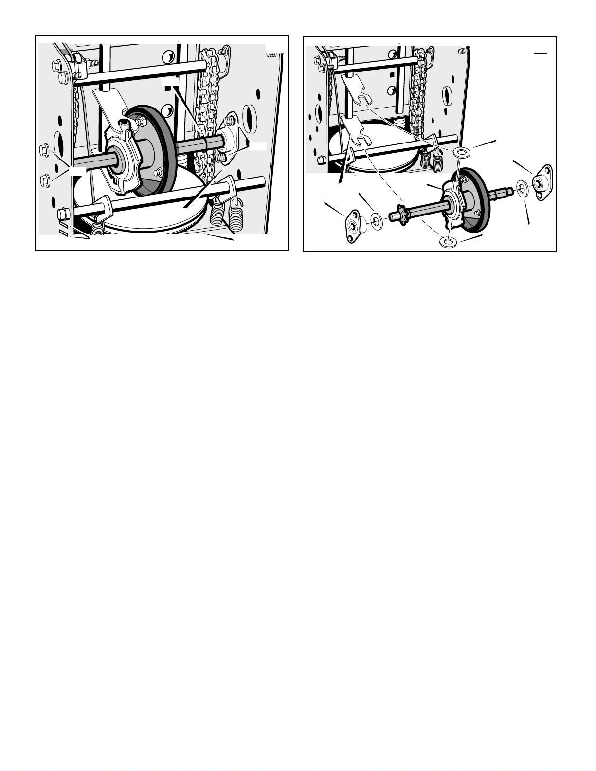
Items Not To Lubricate (Figure 10)
1. Do not lubricate the hex shaft and sprockets (6).
All bearings and bushings are lifetime lubricated. For storage, put a slight
amount of 5W-30 motor oil on a cloth and
w
ipe the h
prevent rust.
rease or oil comes in contact with the
2. If g
disc drive plate (1)
(3),
the friction wheel (3) can be damaged.
Make sure to thoroughly clean the d
plate (1) a
4).
s, away from fire or flame.
c drive plate (1) or the friction
ex shaft and sprockets (6) to
or the friction wheel
isc drive
nd the friction wheel (3).
Page 16
CAUTION: Any greasing or oiling of the
above components can cause contamination of the friction whe
drive plate (1) or the friction whe
come contaminated with grease or oil,
damage to the friction whe
3. T
he auger gear case is lubricated at the factory and does not require additional lubricat
ion. If for some reason the lubricant leaks
o
ut, h
ave the auger gear case checked by a
factory authorized service center.
el (3). If the disc
el (3) be-
el will result.
How To Adjust The Height Of The Skids
(Figure 2)
This snow thrower is equipped with two height
adjustable skids (7). These skids elevate the
f
ront of the snow thrower.
faces, such as a paved driveway or walk, adjust
the skids as follows.
1. Put th
2. M
3. Put th
4. L
NOTE: For rocky or une
the front of the snow thrower by moving the
a
e snow thrower on a level surface.
ake sure both tires are equally inflated.
The correct air pressure is 14 PSI (1 BAR) to
1
7 PSI (1.25 BAR). Do not exceed the maxi-
m
um amount of air pressure shown on the
s
ide of the tire.
e extra shear bolts (found in the parts
bag)
under each end of the scraper bar (15)
next to the a
oosen the mounting nuts (16) that hold the
adjustable skids (7).
snow thrower down, raise each adjustable
s
kids (7)
djustable skids (7) down.
a
s gravel, rocks or other debris, if struck
by the impeller, can be thrown with suffic
ient force to cause personal injury, prope
rty damage or damage to the snow thrower.
djustable skids (7).
. Tighten the mounting nuts (16).
WARNING: Be certain to maintain
proper ground clearance for the
a
rea to be cleared. Objects such
For normal hard sur-
To bring the front of the
ven surfaces, raise
How To Adjust
The Scraper Bar (Figure 2)
After considerable use, the scraper bar (15) will
become worn. The s
junction with the skids, must be adjusted to allow
1
/8 inch clearance between the s
(15)
and the sidewalk or area to be cleared.
1. Put th
2. M
3. L
4. Adjust the s
5. Ti
6. To
e snow thrower on a level surface.
ake sure both tires are equally inflated.
The correct air pressure is 14 PSI (1 BAR) to
1
7 PSI (1.25 BAR). Do not exceed the maxi-
m
um amount of air pressure shown on the
s
ide of the tire.
oosen the carriage bolts and nuts that hold
the s
craper bar (15) to the auger housing
(4).
clearance between the s
the sidewalk or area to be cleared.
ghten the carriage bolts and nuts. Make
sure that the s
the sidewalk or area to be cleared.
extend the life of the scraper bar (15),
remove and reverse the mounting of the
s
craper bar (15).
craper bar (15), in con-
craper bar
craper bar (15) to allow 1/8 inch
craper bar (15) and
craper bar (15) is parallel with
OM6400
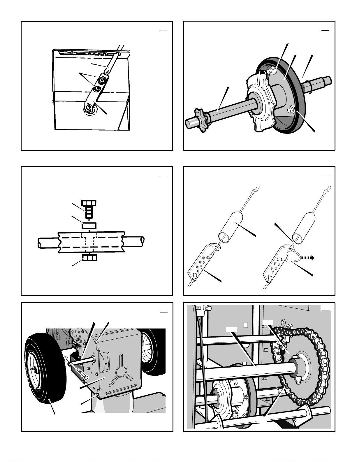
How To Check And Adjust The Cables
The traction drive cable and the auger drive
cable are adjusted at the factory.
use, a cable can become stretched and must be
checked and adjusted as follows.
How To Check The Cables (Figur
1. To check for correct adjustment, disconnect
the “Z” fitting (1) f
ove the drive lever (2) forward until the
2. M
drive lever (2) is contacting the plastic
bumper (3).
3. The control cable is correctly adjusted if the
c
enter of the “Z” fittin
with the hole in the d
is n
o slack in the cable .
How To Adjust The Aug
emove the gas from the gas tank. Stand
1. R
the snow thrower up on the front end of the
a
uger housing.
WARNING: Dra
door
2. (Figure 11) Disconnect the “Z” fitting (1)
from the d
3. (Figur
pose the spring (5).
th
end (
4. H
just the loc
slack is removed.
ull the cable (6) back through the spring
5. P
(5).
6. (Figur
drive lever (2).
NOTE: When the auger drive belt is adjus
or replaced, check and adjust the cable.
How To Adjust The Traction Drive Cable
1. R
the snow thrower up on the front end of the
a
uger housing.
2. (Figure 16) Loosen the bolts (3) on each
side of the bottom panel (2).
3. R
4. (Figur
from the t
5. (Figur
cable adjustment bracket (4).
ush the bottom of the traction control
6. P
cable (5)
bracket (4) u
moved.
7. R
adjustment bracket (4).
(6) d
ull the traction control cable (5) up
8. P
th
ut the cable boot (3) over the cable ad-
9. P
justment bracket (4).
10.(Figur
traction drive lever (2).
rive lever (2).
e 12) Pull the spring cover up to ex-
rough the spring (5) to expose the square
7) on the cable (6).
old the square end (7) with pliers and ad-
e 11) Connect the “Z” fitting (1) to the
emove the gas from the gas tank. Stand
WARNING: Drain the gasoline outdoor
emove the bottom panel (2).
e 11) Disconnect the “Z” fitting (1)
raction drive lever (2).
e 22) Slide the cable boot (3) off the
through the cable adjustment
emove the “Z” hook (6) from the cable
own to the next adjustment hole.
rough the cable adjustment bracket (4).
e 11) Install the “Z” fitting (1) to the
rom the drive lever (2).
rive lever (2) and there
s, away from fire or flame.
Push the cable (6)
knut (8) in or out until the excess
s, away from fire or flame.
ntil the “Z” hook (6) can be re-
During normal
e 11)
g (1) is aligned (4)
er Drive Cable
in the gasoline out-
ted
Move the “Z” hook
16
ENGLISH
11.(Figur
12.(Figur
13.Ti
How To Adjust The Belts
The belts will stretch during normal use. If you
need to adjust the belts due to wear or stretch,
p
roceed as follows.
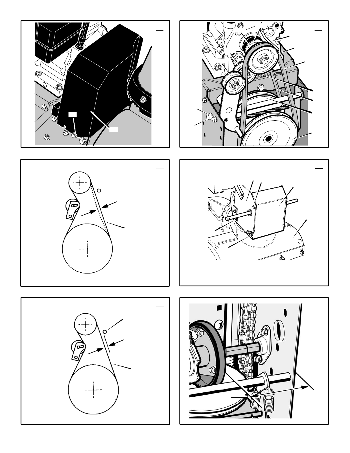
How To Adjust The Auger Drive Belt
If the snow thrower will not discharge snow,
check the adjustment of the auger drive cable.
See “How To Check And Adjust Th
the Maintenance section. If the adjustment is
c
orrect, then check the condition of the auger
d
rive belt. If the auger drive belt is damaged,
r
eplace the auger drive belt. See “How To
place The Belts” in the Maintenance section. If
t
he auger drive belt is loose, adjust as follows.
1. Disconnect the spark plug wire.
2. (Figur
3. (Figur
4. Ti
5. (Figur
6. (Figur
7. C
8. Attach the spark plug wire.
Tr
The traction drive belt has constant spring pres-
ure and does not require an adjustment. If the
s
t
raction drive belt is slipping, replace the belt.
S
nance section.
How To Replace The Belts
The drive belts are of special construction and
must be replaced with original factory replacem
rized service center.
Some steps require the assistance of a second
person.
How To Remove the Auger Drive Belt
I
f the auger drive belt is damaged, the snow
thrower will not discharge snow. Replace the
d
amaged belt as follows.
1. Disconnect the spark plug wire.
2. (Figur
3. R
4. (Figur
e 10) To check the adjustment, depress the drive lever and check the length
“A”
of the drive spring (7). In correct adjustment, the length “A”
is as follows:
m
inimum 3 inches (76 mm.)
m
aximum 3-3/8 inches (85 mm.).
e 16) Install the bottom panel (2).
ghten the bolts (3) on each side of the bot-
tom panel (2).
e 13) Remove screw (2) from belt
cover (1).
pulley (3)
toward the auger drive belt (4).
Check the tension on the a
(4).
belt (4)
ate pressure. If th
repeat the adjustment.
screw (2).
cable. See “How To Check And Adjust The
C
action Drive Belt
ee “How To
ent belts available from your nearest autho-
side of the bottom panel (2).
cover (1).
Remove the belt cover (1).
e 14) Loosen the nut (2) on the idler
Move the idler pulley (3) 1/8 inch
ghten the nut (2).
e 15) Depress the auger drive lever.
In correct adjustment, the auger drive
will deflect 1/2 inch (5) with moder-
e 13) Install the belt cover (1). Tighten
heck the adjustment of the auger drive
ables” in the Maintenance section.
Replace The Belts” in the Mainte-
e 16) Loosen the bolts (3) on each
emove the bottom panel (2).
e 13) Remove screw (2) from belt
Remove the belt cover (1).
of the drive spring (7)
e Cables” in
Re-
uger drive belt
e adjustment is not correct,
Page 17
engine pulley
Page 18
WARNING: For safety and to protect the machine, use only original
e
quipment shear bolts.
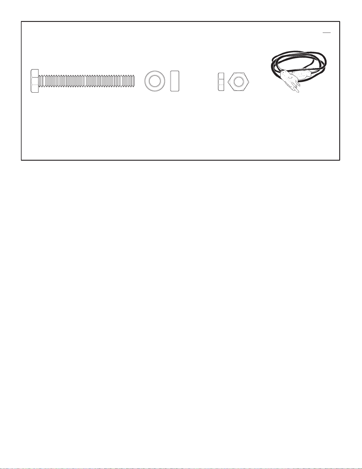
To replace a broken shear bolt, proceed as follows. Extr
sembly parts bag.
1. (Figure 2) M
2. Disconnect the spark plug wire. Make sure
3. (Figure 9) Lubricate the auger shaft Zerk
4. (Figur
5. C
a shear bolts are provided in the as-
the stop position. Disengage all controls.
ll moving parts have stopped.
a
fitting (1),
the hole in the auger shaft. Install the new
s
hear bolt (2), spacer (3) and loc
onnect the spark plug wire.
ove the throttle control (13) to
if equipped, with a grease gun.
e 21) Align the hole in the auger with
knut (4).
How To Prepare The Snow Thrower For
Storage
WARNING: Do not remove gasoline
while inside a building, ne
or while you smoke. Gasoline
f
umes can cause an explosion or a fire.
1. Drain the fuel tank.
et the engine run until it is out of gasoline.
2. L
rain the oil from the warm engine. Fill the
3. D
engine crankcase with new oil.
emove the spark plug from the cylinder.
4. R
Pour one ounce of oil into the cylinder.
ly pull the recoil-start grip so that the oil will
p
rotect th
in the cylinder.
e cylinder. Install a new spark plug
ar a fire,
Slow-
5. T
horoughly clean the snow thrower.
ubricate all lubrication points. See the Main-
6. L
tenance section.
7. Be sure that all nuts, bolts and screws are
securely fastened. Inspect all visible moving
p
arts for damage, breakage and wear.
place if necessary.
over the bare metal parts of the blower
8. C
housing, auger,
rust preventative lubricant.
ut the unit in a building that has good ven-
9. P
tilation.
f the machine must be stored outdoors,
1
0.I
block up the snow thrower to be sure the ent
ire machine is off
over the snow thrower with a suitable pro-
11.C
tective cover that does not retain moisture.
D
o not use plastic.
and the impeller with spray
the ground.
Re-
How To Order Replacement Parts
The replacement parts are shown either on the
back pages of th
separate Parts List Book.
U
se only manufacturer’s authorized or approved
eplacement parts.
r
Do not use attachments or accessories not
specifically
is Instruction Book or in a
ENGLISH
ecommended for this unit. In order to obtain
r
p
roper replacement parts you must supply the
m
odel n
umber (see nameplate).
Replacement parts, except for the engine,
ransmission, transaxle or diff
t
available from the store where the product was
p
urchased, a service shop recommended by the
store or from a “Adisam Inc.1-800-345-6007
W
hen ordering the following information is
r
equired:
(
1) The Model Number
(
2) Serial Number
(
3) Part Number
(4) Quantity
erential, are
TROUBLE SHOOTING CHART
TROUBLE CAUSE CORRECTION
Difficult starting Defective spark plug. Replace spark plug.
Water or dirt in fuel system. Use carburetor bowl drain to flush and refill with
Engine runs erratic Blocked fuel line, empty gas tank, or stale
Engine stalls Unit running on CHOKE. Set choke lever to RUN position.
Engine runs erratic;
Loss of power
Excessive vibration Loose parts: damaged impeller Stop engine immediately and disconnect spark
Unit fails to propel itself Drive belt loose or damaged. Replace drive belt.
Unit fails to discharge snow Auger drive belt loose or damaged. Adjust auger drive belt; replace if damaged.
gasoline
Water or dirt in fuel system. Use carburetor bowl drain to flush and refill with
Incorrect adjustment of traction drive cable Adjust traction drive cable.
Worn or damaged friction wheel. Replace friction wheel.
Auger control cable not adjusted correctly. Adjust auger control cable.
fresh fuel.
Clean fuel line; check fuel supply; add fresh
gasoline
fresh fuel.
plug wire. Ti
necessary repairs. If vibration continues, have
t
he unit serviced by a competent repairman.
ghten all bolts and make all
OM6400
Shear bolt broken Replace shear bolt
Discharge chute clogged. Stop engine immediately and disconnect spark
Foreign object lodged in auger Stop engine immediately and disconnect spark
plug wire. Clean discharge chute and inside of
a
uger housing.
plug wire. Remove object from auger.
18
Page 19
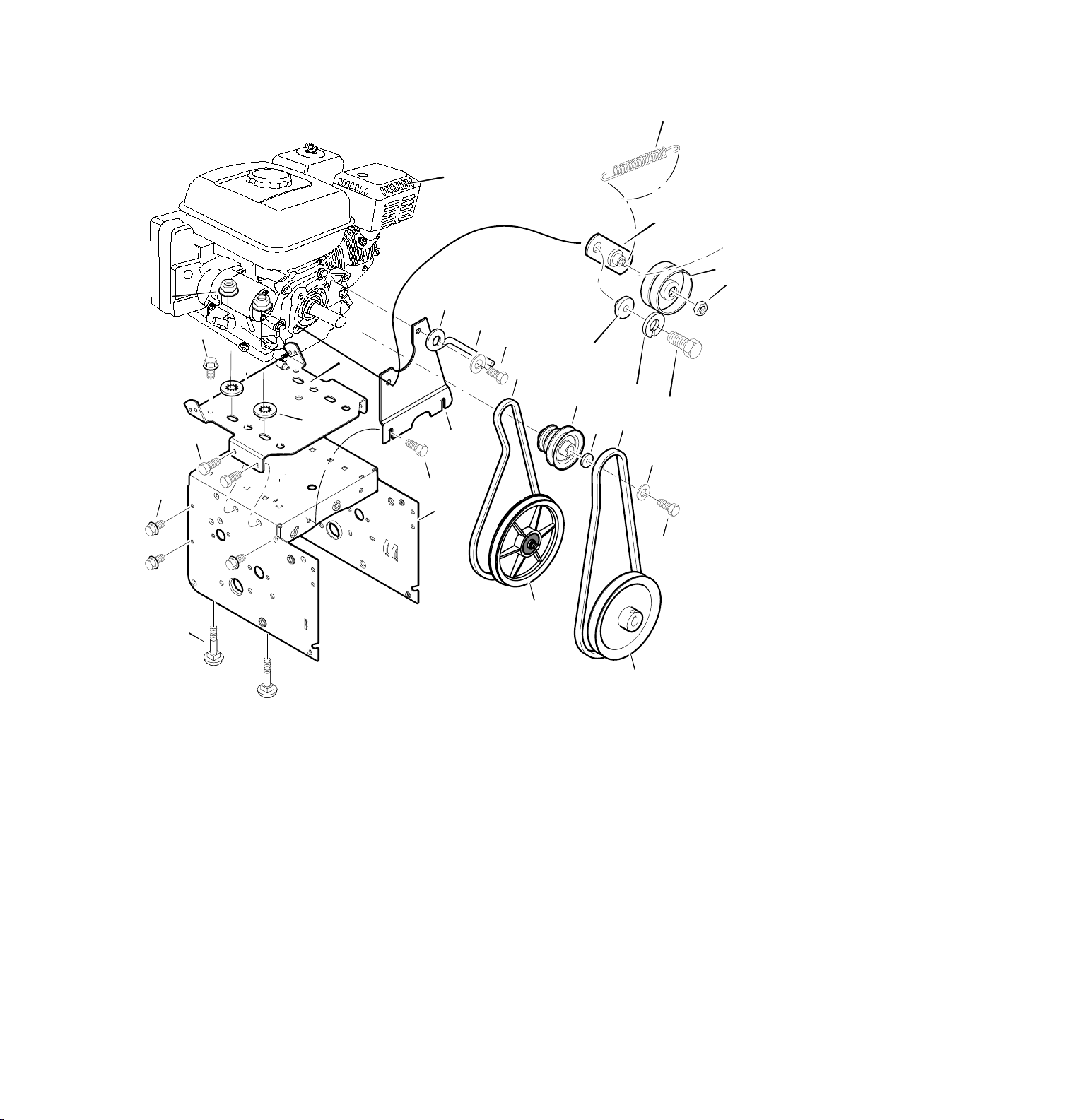
MODEL 6400 REPAIR PARTS
ENGINE
16
2
12
17
5
25-2
25-1
4
25-3
20
23
22
24
10
12
6
13
15
11
7
8
18
25-2
3
.
Key No
7 710247 WASHER
8 71063 WASHER .38ID
9 71015 SCREW, 3/8-24X1.00
10 37X136 BELT, DRIVE V 3L
11 37X137 BELT, V 4L 38.1MF16” 5-10
12 1501112 YZ BRACKET ASSEMBLY,IDLER
13
14 71060 WASHER,SPLIT
15 910828 SCREW, 5/16-24X 1.00
16 165X164 SPRING IDLER TRACTION DRIVE,
Part No
2 - - - - - - ENGINE
3 2x97 BOLT, CARRIAGE 5/16-18
4 28x76 RETAINER, PUSH
5 710026 NUT, HEX 5/16-18
6 1501109 PULLEY, ENGINE
1501065 BUSHING.IDLER BRACKET
.
Description
OM6400
25-5
25-4
9
Ref.Drive Page
Ref. Auger Housing Page
Key No
.
Part No
17 50793 PULLEY,IDLER
18 6115 NUT,JAM 3/8-16 5-10
20 1501201 GUIDE, BELT
22 71060 WASHER, SPTLK .31X.58X.08
23 1501482 PLATE, ANTI VIBRATION
24 910828 SCREW, 5/16-24X 1.00
25 - - - - - - FRAME ASSEMBLY
25-1 1501062E245 PLATE, ENGINE MOUNT
25-2 310169 SCREW, TAP 1/4-20 X .63
25-3 780055 SCREW, TAP 5/16-18 X .50
25-4 1501049E245 FRAME, MOTOR BOX
25-5 26x263 SCREW
-- F-021081L OWNER’S MANUAL
.
Description
19
ENG100A
Page 20
6134
6135
6136
6137
Page 21
MODEL 6400 REPAIR PARTS
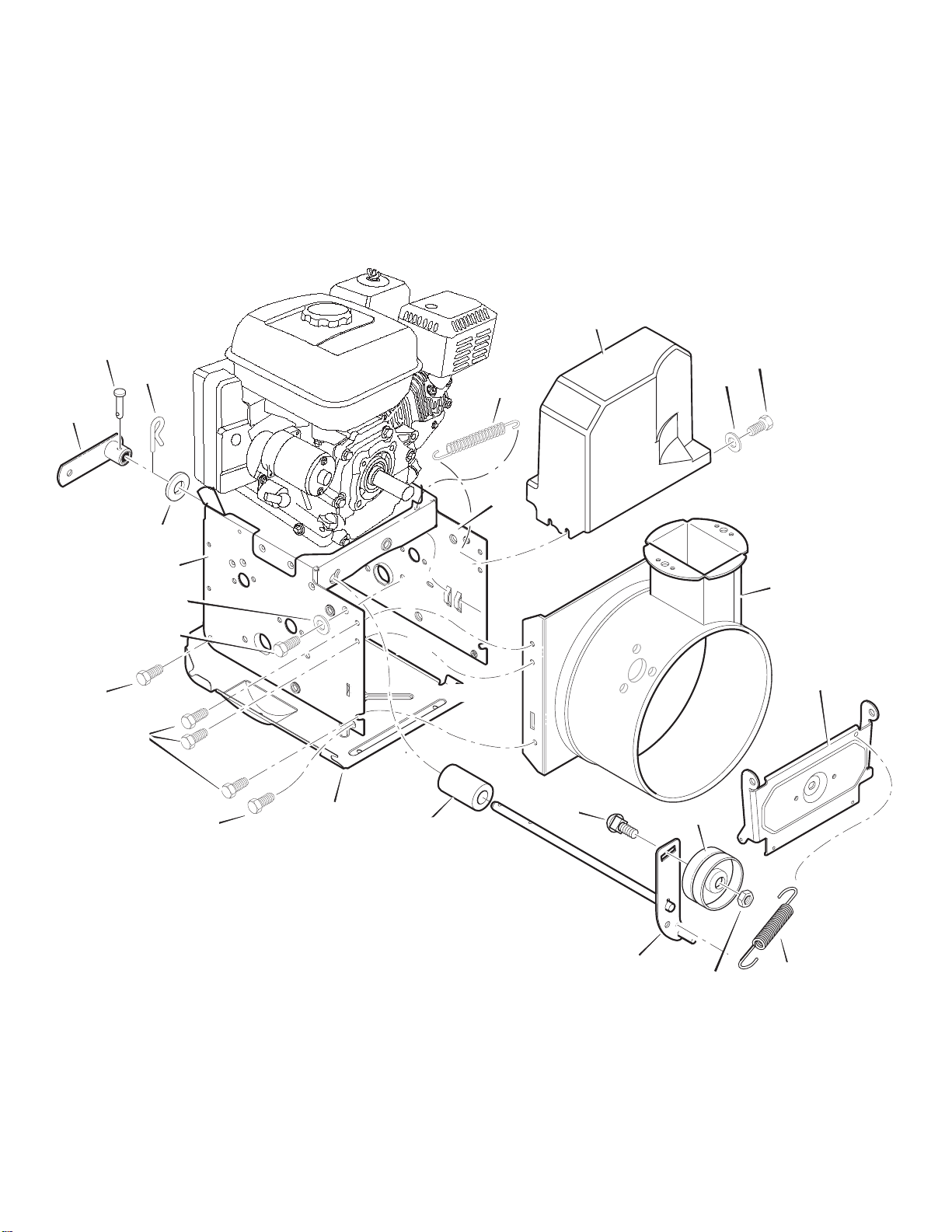
FRAME
160
106
105
108
111
Ref. Engine Page
166
162
91
122
145
112
162
166
Ref. Auger
Housing Page
Ref. Drive
Page
OM6400
91
90
168
21
110
103
148
107
149
FRA100A
Page 22

MODEL 6400 REPAIR PARTS
FRAME
Key No. Part No. Description
90 1501055E701 COVER, BOTTOM
91 310169 SCREW, 1/4-20X .63
103 1501126 YZ IDLER ASSEMBLY, AUGER
105 711682 PIN, HAIR .38DIAX1.64LG
106 761761 PIN, KLIK 3/16” DIA
107 165X159 SPRING, TENSION
108 761675 YZ ASSY., SPRING ATTACH
110 585781 BOLT, 3/8-16X1.25 CARR.
111 711617 WASHER, FLAT
122 25X020 SCREW, TAP 5/16-18 X .50
123 70984 BOLT
148 50793 PULLEY, IDLER
149 6115
160 1501053 COVER, BELT
162 26X306 SCREW, TAP 1/4-20 X .63 YZ
166 71067 WASHER, FLAT
168 1501200 SPACER, AUGER BRACKET
NUT, JAM 3/8-16
OM6400
22
Page 23
MODEL 6400 REPAIR PARTS
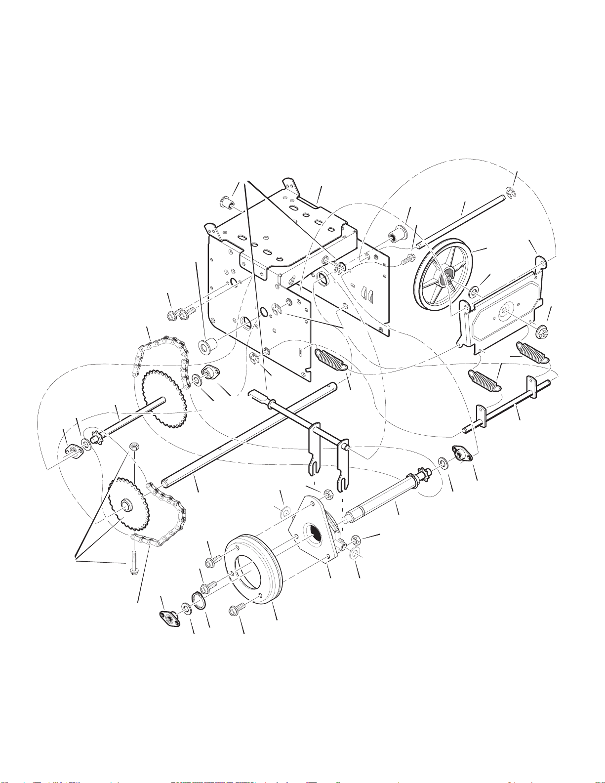
DRIVE
203
204
236
Ref. Wheel Page
206
201
Ref. Shift Yoke Page
203
204
Ref. Frame Page
232
229
234
Ref. Wheel
Page
221
229
200
225
223
226
227
234
230
Ref.
Wheel Page
OM6400
208
220
213
218
Ref. Wheel
Page
213
217
213
238
212
215
23
210
220
218
207
215
238
Page 24

MODEL 6400 REPAIR PARTS
DRIVE
Key No. Part No. Description
200 1501092 YZ LF AXLE, SWING PLATE YZ
201 579851 CHAIN, ROLLER #42x19.00
203 334163 BEARING AND RETAINER, ASSY
204 579858 WASHER
206 780055 SCREW, TAP 5/16-18x0.5
207 1501100 ASSY, HEX SHAFT
208 579868 CHAIN, ROLLER #36x18.00 LG
210 337029 BEARING, TRUNION CLUTCH R
212 1501435 WHEEL, FRICTION DISC
213 001x38 BOLT
215 303008 NUT, KEPS HEX 1/4-20
217 579859 RING, RETEXT
218 579858 WASHER
220 334163 BEARING AND RETAINER, ASSY
221 780055 SCREW, TAP 5/16-18 x .5
223 1501115 ASSY, FRICTION PULLY
2
25 1
226 1501158 SPACER, FRICTION PULLEY
227 15X114 NUT, FLANGE LOCK 3/8-24
229 11X30 RETAINER, RING
230 1501107 YZ LF ASSY, SPRING LINK YZ
232 11X30 RETAINER, RING
234 165X112 SPRING, EXTENSION
501057 YZ LF PLATE, SWINGING YZ
OM6400
236 1501090 WLD, INTERMED SPROCKET 33T/7
238 71074 WASHER, FLAT
24
Page 25
MODEL 6400 REPAIR PARTS
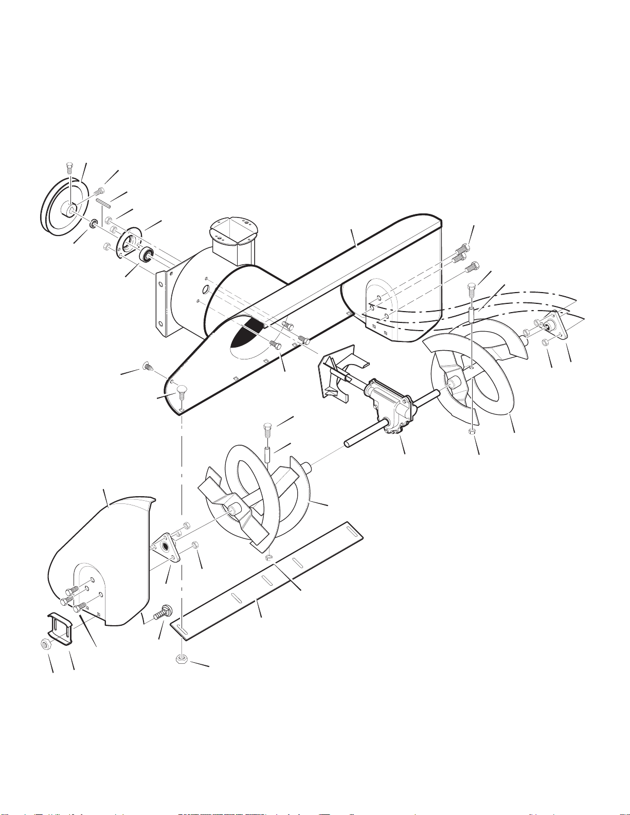
AUGER HOUSING
485
480
509
491
484
482
499
511
490
493
522
523
500
527
522
523
520
526
525
544
540
527
500
541
525
526
514
510
524
521
Ref. Gear Case
Page
524
OM6400
25
Page 26

MODEL 6400 REPAIR PARTS
AUGER HOUSING
Key No. Part No. Description
480 1501211 PULLEY
482 2001022 KEY, SQUARE
484 577400 SCREW, 5/16-18 X 0.63
485 1501158 SPACER, FRICTION PULLEY
490 582957 YZ RETAINER, BALL BRNG
491 43846 BEARING, BALL
493 001X92 BOLT, HEX - 0.31-18X0.50
499 710026 NUT, 5/16-18 HEXWDFLLK
500 1501436E245 HOUSING, ASSY
509 760040 PLUG, CHRISTMAS TREE
510 760657E701 BLADE, SCRAPER
511 340720 BOLT, 1/4-20X.75
514 710026 NUT
520 1501441E701 AUGER, ASSY, LH
521 1501440E701 AUGER, ASSY, RH
522 9524 SCREW, 1/4-20X1.75
523 3943 SPACER, SLEEVE
524 73826 NUT, 1/4-20
525 9517 BEARING, FLANGE
526 711862 NUT, TOPLOCK 5/16-18
527 9357 SCREW, 5/16-18X .75
540 762377E701 SKID, HEIGHT ADJUST
541 340720 BOLT, 5/16-18 X .75
OM6400
544 710026 NUT, 5/16-18 REGHEX
26
Page 27
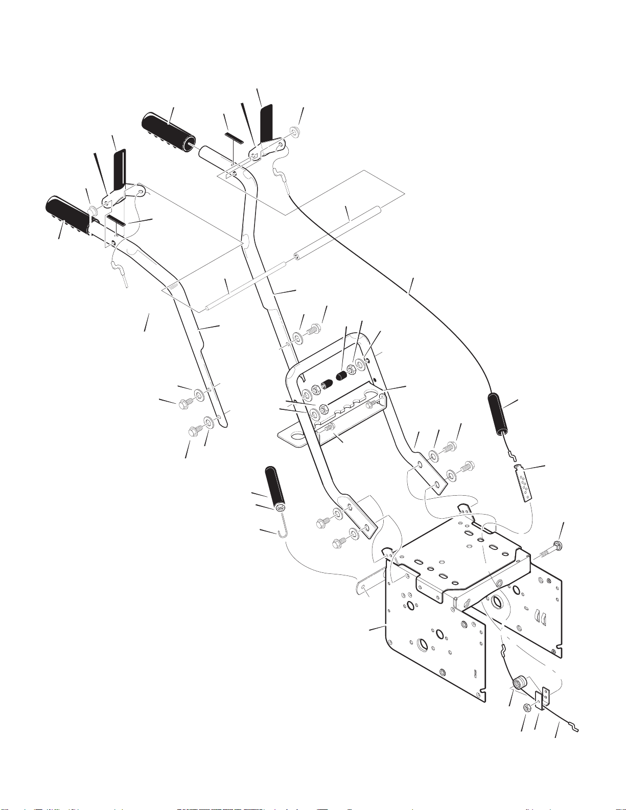
MODEL 6400 REPAIR PARTS
HANDLE
766
729
734
730
766
739
729
731
739
734
735
741
724
725
756
725
733
721
765
764
744
727
726
720
725
724
728
757
727
726
740
755
750
752
765
751
743
763
OM6400
Ref. Engine Page
27
HDL100A
759
764
760
762
Page 28

MODEL 6400 REPAIR PARTS
HANDLE
Key No. Part No. Description
720 337056E701 HANDLE, UPPER LH
721 337057E701 HANDLE, UPPER RH
724 11234 SCREW, 5/16-18X2.75
725 71071 WASHER, FLAT
726 71060 WASHER, SPTLK .31X.58X.08
727 15X144 NUT, 5/16-18 REGHEX YZ
728 11261 STOP, RED PLASTIC
729 337399 GRIP-HANDLE FINGER
730 337816E701 LEVER, ASSY CLUTCH DRIVE RH
731 337815E701 LEVER, ASSY CLUTCH DRIVE LH
733 337381 ROD, PIVOT CLUTCH
734 761105 NUT, PUSH ON CAP
735 337373 SPACER-HANDLE
739 4049 BUMPER, RECTANGLE
740 1501123 CABLE, CLUTCH 28.44L
741 761872 CABLE, AUGER CLUTCH
743 313441 BRACKET, CABLE ADJUSTER
744 6138 SPRING, AUGER CLUTCH
745 15X145 NUT, 1/4-20 NYLOCK YZ
750 339541E701 HANDLE, LOWER
751 70984 SCREW, TAP 5/16-18 X .75
752 71060 WASHER, SPTLK
755 337407E701 BRKT, GEAR SELECTOR
756 6751 SCREW, 5/16-18X2.00
757 310169 SCREW, 1/4-20 X 0.63
759 579860 SPOOL-CABLE, AUGER CLUTCH
760 1501059 YZ BRACKET, CABLE SPOOL YZ
762 1501122 CABLE, LOWER DRIVE 12”
OM6400
763 001798 BOLT, HEX 1/4-20 X 1.50 YZ
764 780029 NUT
765 308146 BOOT, CLUTCH SPRING
766 337380 GRIP
28
Page 29
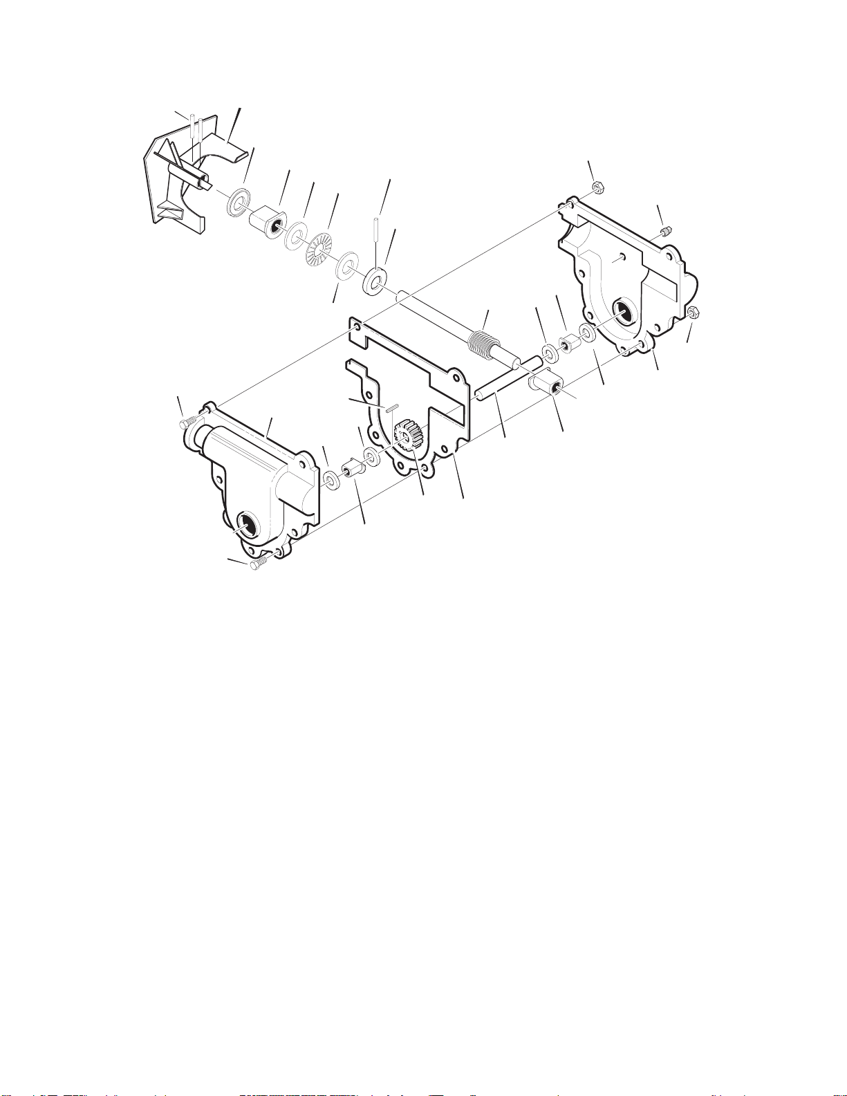
MODEL 6400 REPAIR PARTS
GEAR CASE
341
340
303
303
327
300
326
324
310
324
316
325
312
311
323
322
315
314
321
313
304
306
311
312
304
301
310
320
GEAR104A
OM6400
* (NOT ILLUSTRATED)
Key No. Part No. Description
300 10577 CASE, GEAR, RH
301 10576 CASE, GEAR, LH
303 710025 SCREW
304 15x143 NUT
306 9344 SCREW
310 9566 SEAL, OIL
311 6139 B
312 48275 WASHER, FLAT
313 1501189 SHAFT, OUTPUT
314 51279 GASKET
315 51405 GEAR, WORM
316 431787 KEY, WOODRUFF
320 50221 BRNG, FL
321 1501191 SHAFT, INPUT
322 580295 COLLAR, THRUST
323 454565 PIN, SPRING
324 48275 WASHER, FLAT
325 50684 BRNG, ROLL
326 6139 BRNG, FL
327 9566 SEAL, OIL
340 1501188E701 IMPELLER
341 454565 PIN, SPRING
* 333431 10oz LUBRIPLATE
EARING, FL
29
Page 30
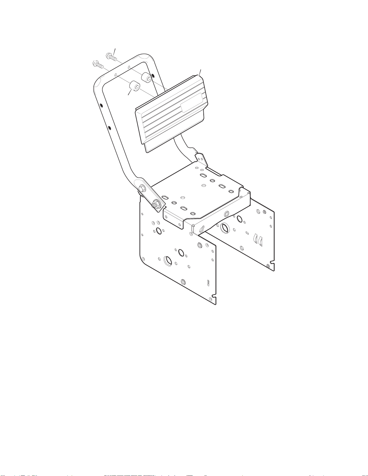
MODEL 6400 REPAIR PARTS
CONTROL PANEL
771
770
772
OM6400
Key No. Part No. Description
770 584559 PANEL
771 341026 SCREW
772 3943 SPACER, SLEEVE
30
Page 31
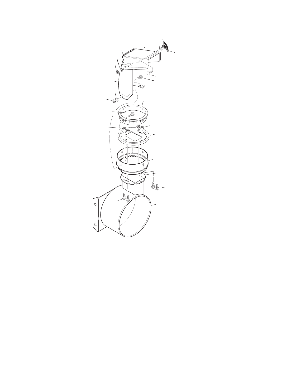
MODEL 6400 REPAIR PARTS
DISCHARGE CHUTE
603
609
600
601
584
602
583
600
600
610
596
597
599
582
609
606
611
OM6400
607
607
Ref. Auger Housing Page
Key No. Part No. Description
582 585280 BOLT, 5/16-18 X 1.00 CARR.
583 71071 WASHER, FLAT
584 71038 NUT, 5/16-18 NYLOCK
596 71071 WASHER
597 1501260 KNOB, WING 3.00
598 71037 NUT, 5/16-18 REGHEX
599 002X97 BOLT, 5/16-18 CARR. YZ
600 762222 CHUTE ASSEMBLY
601 586280 BOLT, 5/16-18 CARR.
602 71071 WASHER, FLAT
603 71038 NUT, 5/16-18 HEXNYL
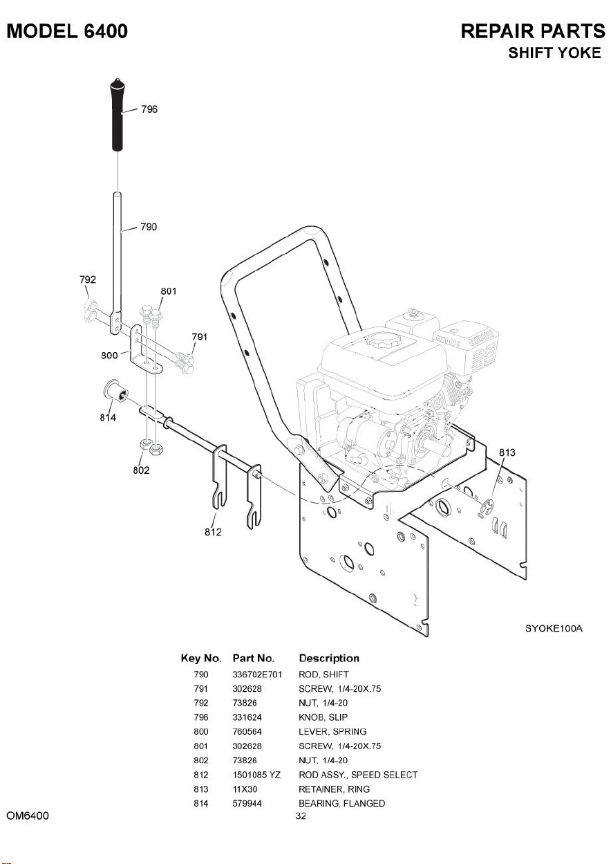
606 585214 YZ CHUTE COLLAR
607 340714 SCREW, 1/4-20 X 0.75
609 15X145 NUT, 1/4-20 HEX NYLOCK YZ
610 337227 RETAINER RING INNER
611 1501282 RETAINER RING OUTER
31
CHUTE100A
Page 32
Page 33
MODEL 6400 REPAIR PARTS
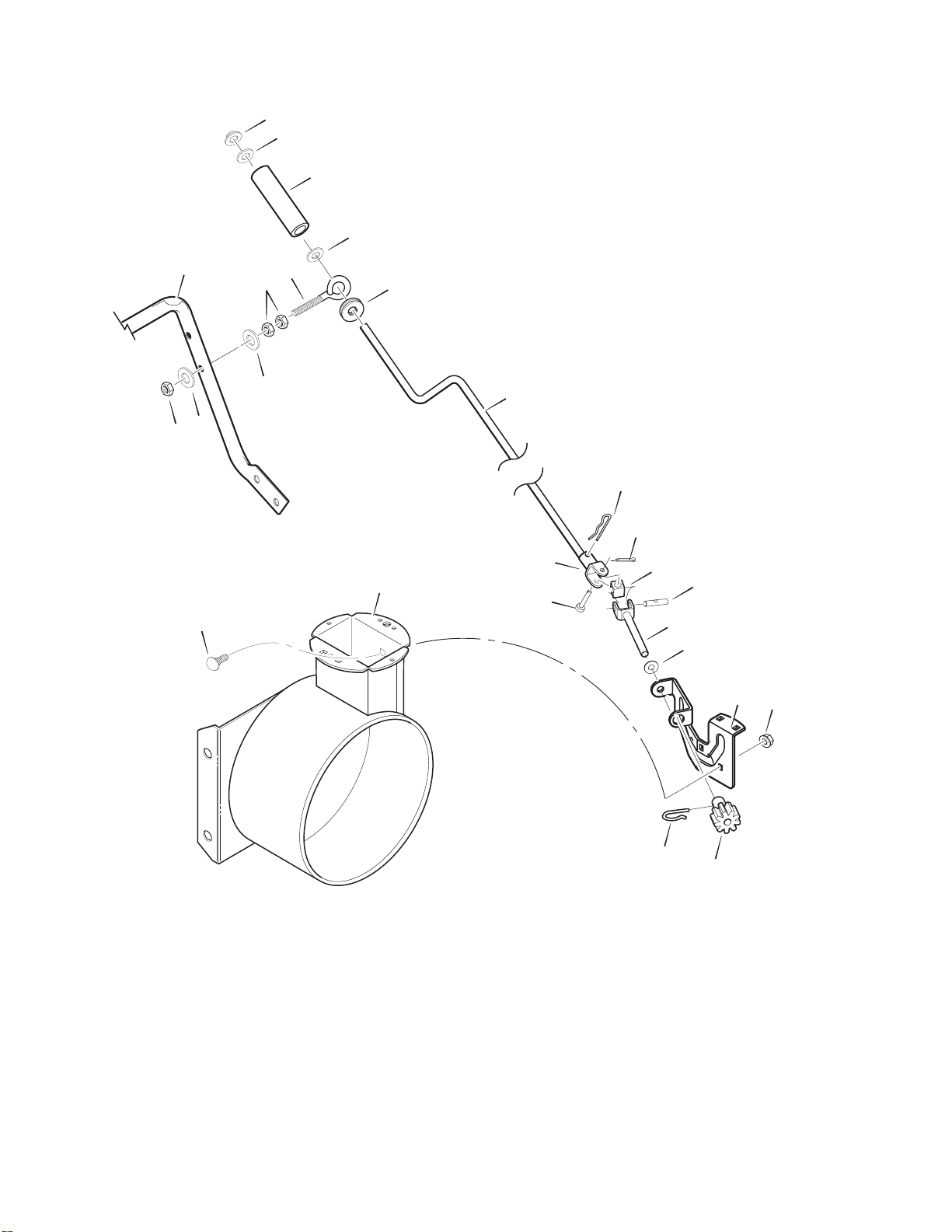
CHUTE ROD
856
855
854
855
Ref. Handle Assy
864
867
868
863
864
860
Ref. Auger Housing Assy
861
870
852-8
852-1 1
852-9
852-5
852-13
852-1
852-2
852-10
852-6
869
852-7
852-3
CROD105B
Key No. Description Part No. Key No. Description Part No.
852-1 ASSEMBLY, YOKE & ROD 1501309 YZ
852-2 WASHER, CURVED SPRING 313431
852-3 GEAR, CHUTE ROTATION 9T 1501067
852-5 PIN, COTTER 71082
852-6 BRACKET, GEAR MOUNT 1501306E701
852-7 PIN, HAIR 1501293
852-8 ASSEMBLY, YOKE ADAPTER YZ 1501075 YZ
852-9 PIN, HAIR 711682
852-10 PIN, UNIVERSAL JOINT 578060
852-1 1 PIN, CLEVIS 578309
852-13 HOUSING, UNIVERSAL 578063
OM6400
854 KNOB, SLEEVE 51443
855 FLATWASHER 309312
856 NUT, PUSH ON 3/8” 73664
860 EYE BOLT 3/8-16X6.00 581618
861 GROMMET, EYE BOLT 148
863 NUT, 3/8-16 HEXJAM 71045
864 FLATWASHER .406X.81X.066 71072
867 NUT, 3/8-16 HEXNYL 71046
868 BOLT, CARRIAGE 1/4-20 X 1.00 002X98
869 NUT 15X145
870 CRANK, ASSY CHUTE 1501074 YZ
33
Page 34
MODEL 6400 REPAIR PARTS
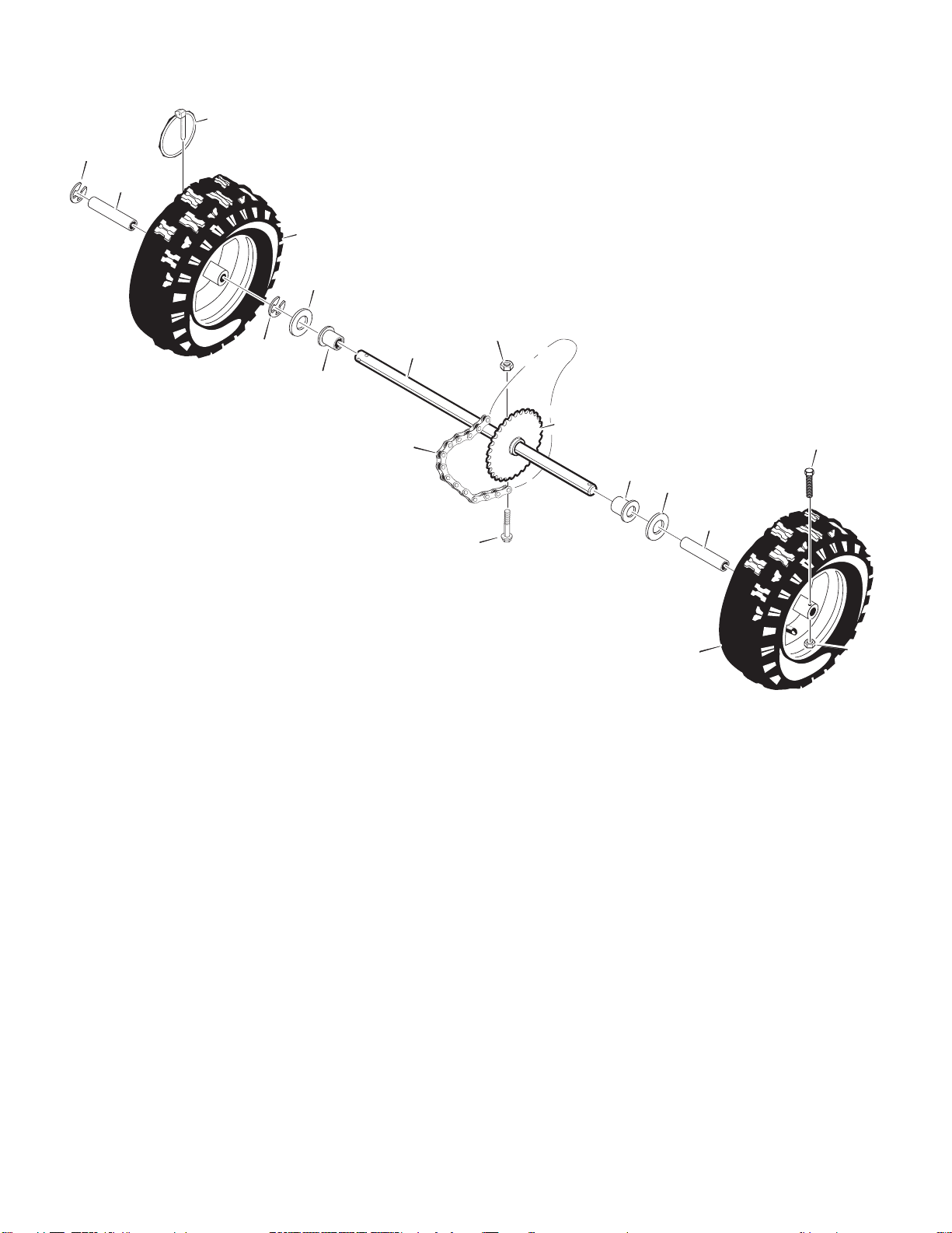
WHEELS
679
678
673
675
671
654
678
655
Ref. Drive Page
650
652
655
676
671
653
Key No. Part No. Description
650 1501283 SHAFT, AXLE
652 1501089 SPRKT & HUB
653 01x193 SCREW, 1/4-20 x 1.75
654 15x145 NUT, 1/4-20 HEX NYLOCK
655 1501114 BEARING, AXLE
671 712120 FLATWASHER
673 1501139 BUSHING, WHEEL
675 318503 TIRE & RIM
676 577015 SCREW, 1/4-20X1.75 HH
677 15x145 NUT, 1/4-20 HEX NYLOCK
678 6140 RING, RET
679 73842 PIN, KLIK .25 X 1.38 DIA
675
673
677
WHL100A
OM6400
34
 Loading...